P3YSPOTCELL0011Spotcell 612
Spotwave Wireless Ltd.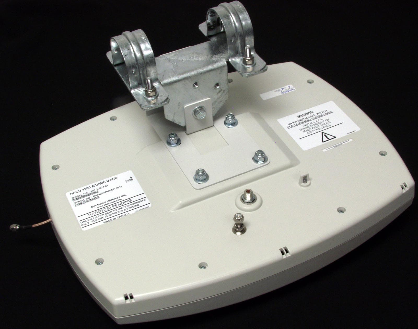
Click to zoom
Application Details
- Equipment Class
- PCB - PCS Licensed Transmitter
- Date of Grant
- Aug 30, 2004
- Application Purpose
- Original Equipment
- Date of Application
- Aug 30, 2004
- Equipment Note
- Spotcell 612
- Frequency Range
- 1930.00000000 - 1970.00000000
- Company
- Spotwave Wireless Ltd.
- Country
- Canada
Documents & Files
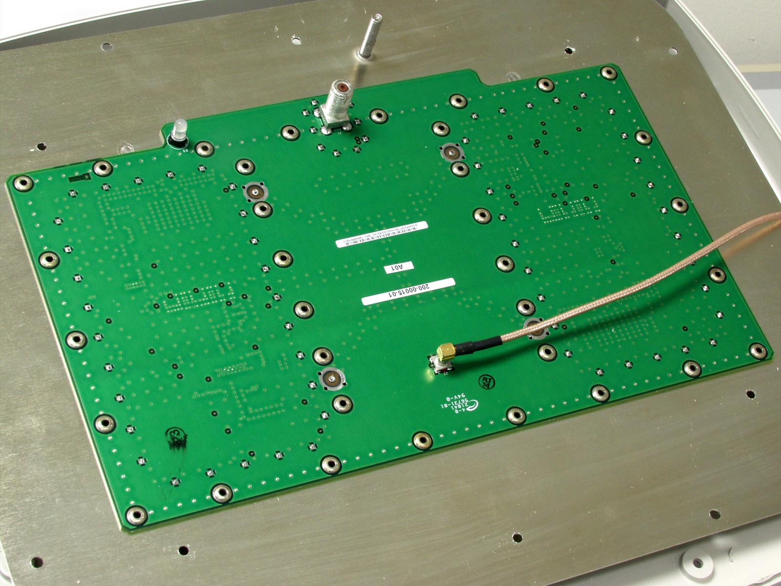
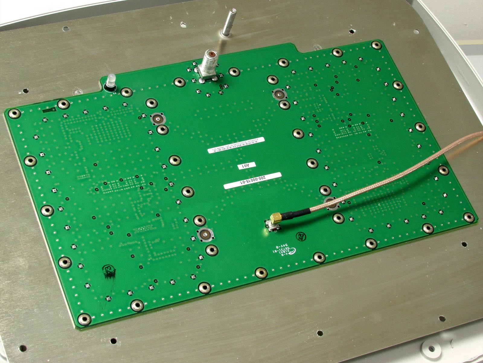
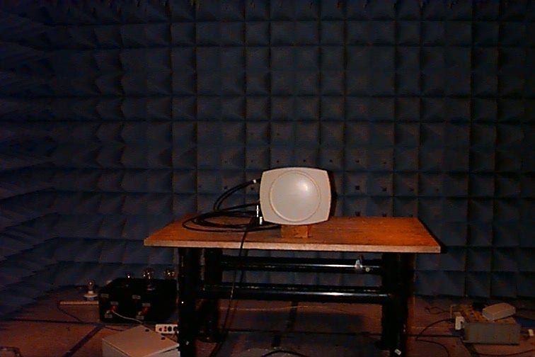
Document Text
Text extracted from the exhibit documents filed with the FCC. Open a document above to read the original.
Users Manual
TM SpotCell612 Adaptive Repeater Quick Installation Guide www.spotwave.com Spotwave Wireless Inc. 1 Hines Road, Ottawa ON K2K 3C7 Canada 780-00011-01-02 Spotwave and SpotCell are trademarks of Spotwave Wireless Inc. Patents pending. Parts List • Mounting kit • RG-11 Cables • High Power Coverage Unit (HPCU) • Adaptive Repeater Unit (ARU) DU (outward-facing unit) HPCU (coverage unit) • Donor Unit (DU) • Battery Battery ARU ARU mounting bracket Customer Provided Material Typical SpotCell 612 Deployment DU ARU 120 feet 20 to 30 feet IMPORTANT DU & HPCU mounting brackets bag of hardware RG-11 Cable TM If required, more detailed information on installing the SpotCell 612 system can be found in the User Manual. The User Manual is available for downloading at: www.spotwave.com/2003/support/ The AC power connection for the SpotCell 612 system must be completed by a licensed electrician in full accordance with electrical code requirements. All work on electrical utility poles must be done only by those trained for such work. Parts or material that is not included but which is required to install the SpotCell 612 system are: l 110-V AC electrical hook-up for ARU, l Ground bonding material for grounding the ARU, DU and HPCU (cable, ground rods, etc.), l DU and HPCU support poles, l ARU support pedestal (if needed), l Material such as steel bands for attaching to non-wooden supports ,or where fastening with screws is not permitted. Good physical separation between the DU and HPCU, combined with back-to-back positioning of the DU and HPCU units will optimize the coverage area. © 2002 Spotwave Wireless Inc. All rights reserved. Printed in Canada. HPCU Coverage Area 10 feet 30 feet ARU mounts on stub pole or HPCU support pole. 40-ft HPCU Cable - Included DU Cable - Order from Spotwave 3. Remove ARU front panel TM SpotCell 612 Quick Install Guide 5. Install back-up battery 6. Replace panel & connect ground cable 2. Attach ARU 1. Install ARU bracket 4. Connect AC power 12. Set the system to Active mode 8. Install ARU - DU Coaxial Cable 7. Connect ARU - HPCU Coaxial Cable 9. Set to Install mode & power up 10. Determine DU alignment 11. Mount DU and HPCU 13. DU and HPCU grounding & checklist circuit breaker ground stud battery battery clip panel screws PSU FUSE 2A 250V AC BREAKER ACTIVE SCROLL external ground stud For your safety beware of overhead power lines and underground power and gas lines, and motor vehicle traffic. Failure to maintain a safe distance from power lines or contact with gas lines could result in death or serious injury. Ensure that all appropriate safety measures are practiced at all times. WARNING Loosen the battery clip screw and remove the clip. Connect red wire to (+) positive battery terminal and black wire to (-) neg- ative terminal. Place battery on tray and the provided thermal insulator behind battery. Replace battery clip. Replace front panel and re-fasten panel screws. Connect ground bonding cable to external ground stud on the bottom of the ARU. Follow local and national electrical code requirements for bonding ground cable to a suitable ground. Energize AC power cable but leave the circuit breaker OFF. Using 40-ft RG-11 coaxial cable with green boots, connect HPCU to ARU green RF port. Install coaxial cable as specified. Using an Allen wrench open the ARU door, and remove the two front screws and front cover panel. Connect DU to ARU with RG-11 cable (160-ft typical) ordered from Spotwave. Use back ARU RF port. Install as specified. Set ARU to INSTALL mode by setting ARU mode switch to right position (opposite ACTIVE). Set ARU circuit breaker to closed (ON) position. The HPCU LED shows GREEN when it has proper DC power. Fasten DU mount to support pipe then attach DU. Align DU to the GREEN direction determined by Step 10 (or as specified in the installation service order). Set ARU to ACTIVE with mode switch. Press SCROLL button until LCD shows ‘Signal Strength/Coverage’ bar graph display. Optimize alignment for maximum coverage potential (5 bars on lower display). 1. Bond DU and HPCU units to ground. Follow electrical code requirements. 2. Ensure that there are drip loops on RG-11 at DU and HPCU, unless cable routing is from below. 3. Complete the installation report. 4. Ensure ARU door is properly closed and locked. Second Rotation - Repeat 360-dg rotation. Take note of where LED shows GREEN - this is the direction DU must face for maximum downlink signal strength. First Rotation - At location where downlink signal into DU is best, hold the DU vertical facing away from you. Slowly rotate it in a complete circle. Ignore the LED. Mount the ARU bracket on a support at least 25-ft from the planned HPCU location. Attach the bracket with either the provided screws or alternatively with steel bands. Place the ARU on the mounting bracket. An eye bolt on the ARU is provided to attach a lift rope if required. Fasten the ARU to the bracket with the provided hardware. Ensure AC power line is de-energized (OFF), and ARU circuit breaker is in the open (OFF) position. Locate and aim HPCU for coverage. Mount HPCU (same hardware as DU). HPCU and DU must not face each other. live (black) neutral (white) cable connector ARU Back of HPCU green washer green boots ARU cable connector Back of DU Back to back is best. LED LED Loosen dome nut of 3/4” conduit fitting on cabinet bottom. Route AC power conduit or cable through fit- ting. Tighten dome nut until mild resistance is felt, plus 1/4-turn more (½-turn for armored cable). Terminate live (black) wire on left side of connector block, neutral (white) wire on right side, and ground (green) wire on ground stud.
Users Manual
Spotwave Wireless Inc.i Technical Support The SpotCell TM serial number must be available to authorize technical support and/or to establish a return authorization for defective units. The serial number is located on the back of the High Power Coverage Unit (HPCU), Adaptive Repeater Unit (ARU) and Donor Unit (DU), as well as the box in which they were delivered. Support information may be obtained by accessing the Spotwave Wireless Inc. website at www.spotwave.com. To contact support by telephone, call your local Spotwave vendor, or if you are unable to do so, call Spotwave Wireless at 1-877-610-9586. Important Safety Information Warning! For your safety, beware of power lines and ensure appropriate separation distances, and safety measures, are maintained at all times during the SpotCell equipment installation. If equipment supplied by others is to be used during installation or mounting, follow all equipment manufacturer’s instructions to ensure injury is avoided. If you are installing the SpotCell near high voltage power lines, or in any way are not sure about a safe installation, do not attempt to install it yourself. Call a professional installer for help. The DU and HPCU of the SpotCell are low power transmitters. As with a cell phone antenna, avoid unneccessary contact with the front of the units after installed. Mount the units in a location where people will not approach within 1 meter of the front of the DU or HPCU. SUPPORT, SAFETY AND WARRANTY iiSpotCell 612 Adaptive Repeater Limited Warranty and Limitation of Warranty 1. What is Covered and for How Long? Spotwave Wireless Inc. (“Spotwave”) warrants to the original Purchaser that the Spotwave SpotCell System (the “System”) is free from defects in material and workmanship under normal use and service for a period of 12 months from the date of shipment from Spotwave (the “Limited Warranty Period”). 2. What is Not Covered? This Limited Warranty is conditioned upon proper use of the System by the Purchaser. This Limited Warranty does not cover (and will become null and void in the event of): (a) defects or damage resulting from accident, misuse, abuse, neglect, unusual physical, electrical or electromechanical stress, modification of the System or any part thereof, or cosmetic damage; (b) removal, alteration or defacing of the serial number or other identifying marks on the System; (c) all plastic surfaces and other externally exposed components that are scratched or damaged due to normal use; (d) malfunctions resulting from the use of the System in conjunction with accessories, products or (ancillary) or peripheral equipment not provided by Spotwave; or (e) defects or damage from unauthorized or improper testing, operation, maintenance, installation, servicing or adjustment of the System. Any repairs or replacements provided by Spotwave outside of the Limited Warranty Period (including repairs to or replacement after the end of the Warranty Period), or in excess of the services provided during the Limited Warranty Period, will subject to Spotwave's then prevailing rates. 3. What are Spotwave's Obligations and how do you make a claim? During the Limited Warranty Period, Spotwave will repair or replace, at Spotwave's sole option, without charge to Purchaser, any defective component of the System, provided that the System is returned promptly upon discovery of the defect and during the Limited Warranty Period. To obtain service, Systems must be returned to an authorized service facility in the original packaging or packaging adequate for shipping, accompanied by Purchaser's sales receipt or comparable substitute proof of sale showing the date of purchase and the serial number of the System. A valid RMA is required prior to any return. To locate your nearest authorized service facility, call Spotwave Customer Service at 1-877-610-9586 . Spotwave may, at Spotwave's sole option, use rebuilt, reconditioned, or new parts or components when repairing any System or replace a System with a rebuilt, reconditioned or new System. Repaired Systems will be warranted for a period equal to the remainder of the original Limited Warranty Period for the original System or for 90 days, whichever is longer. All replaced parts, components, boards or equipment shall become the property of Spotwave. If Spotwave determines that any System is not covered by this Limited Warranty, Purchaser must pay the costs for all parts, shipping, and labor charges for the repair or return of such System. 4. What are the Limits on Spotwave's Liability? Spotwave Wireless Inc.iii EXCEPT FOR THE WARRANTY IN PARAGRAPH 1, THE SYSTEMS AND ANY ASSOCIATED SERVICES ARE PROVIDED BY SPOTWAVE ON AS 'AS IS' BASIS AND THERE ARE NO OTHER REPRESENTATIONS, WARRANTIES OR CONDITIONS,EXPRESS OR IMPLIED, WRITTEN OR ORAL, ARISING BY STATUTE, OPERATION OF LAW, COURSE OF DEALING, USAGE OF TRADE OR OTHERWISE, REGARDING THEM OR ANY OTHER PRODUCT OR SERVICE PROVIDED HEREUNDER OR IN CONNECTION HEREWITH BY SPOTWAVE. SPOTWAVE DISCLAIMS ANY IMPLIED WARRANTIES OR CONDITIONS OF DURABILITY, MERCHANT ABILITY, MERCHANTABLE QUALITY, SATISFACTORY QUALITY, NON-INFRINGEMENT OR FITNESS FOR A PARTICULAR PURPOSE. SPOTWAVE DOES NOT REPRESENT OR WARRANT THAT THE SYSTEMS WILL MEET ANY OR ALL OF PURCHASERS' PARTICULAR REQUIREMENTS, THAT THE SYSTEMS WILL OPERATE ERROR-FREE OR UNINTERRUPTED OR THAT ALL ERRORS OR DEFECTS IN THE SYSTEMS CAN BE FOUND TO BE CORRECTED. System performance is dependant upon the performance and availability of services or technology provided by third parties and Spotwave is not responsible for service continuity and reliability, reception, or other performance related limitations associated with use of the Systems. NO AGREEMENTS VARYING OR EXTENDING THE TERMS OF THIS LIMITED WARRANTY WILL BE BINDING ON SPOTWAVE UNLESS IN WRITING AND SIGNED BY AN AUTHORIZED SIGNING OFFICER OF SPOTWAVE THIS LIMITED WARRANTY SHALL NOT EXTEND TO ANYONE OTHER THAN THE ORIGINAL PURCHASER OF THE SYSTEM. SPOTWAVE'S MAX…
Text truncated - open the document above for the full version.
Attestation Statements
Spotwave Wireless Inc. 1 Hines Road, Unit 204 Ottawa ON K2K 3C7 Canada Tel: (613) 591-1662 Fax: (613) 591-8107 www.spotwave.com DATE June 30, 2004 Nemko Canada Inc 303 River Road Ottawa, Ontario, Canada K1V 1H2 Attn: Director of Certification Authority to Act as Agent On our behalf, I appoint Nemko Canada Inc, with head office at 303 River Road, Ottawa, Ontario , Canada, K1V 1H2, to act as our agent in the preparation of this application for equipment certification. I certify that submitted documents properly describe the device or system for which equipment certification is sought. I also certify that each unit manufactured, imported or marketed, as defined in the Federal Communications Commission’s regulations will have affixed to it a label identical to that submitted for approval with this application. For instances where our authorized agent signs the application for certification on our behalf, I acknowledge that all responsibility for complying with the terms and conditions for certification, as specified by Nemko Canada Inc, still resides with Spotwave Wireless Inc, with head office at 1 Hines Road, Ottawa, Ontario, K2K 3C7. Dated this Wednesday Day of June 30 th 20 04 Agency agreement expiration date: June 30, 2005 By: Michael J. Roper Signature Printed Title: Vice President, Product Development On behalf of : Spotwave Wireless Inc Telephone: (613) – 591 – 1662 x 231
Cover Letter(s)
Spotwave Wireless Inc. 1 Hines Road, Unit 204 Ottawa ON K2K 3C7 Canada Tel: (613) 591-1662 Fax: (613) 591-8107 www.spotwave.com DATE June 30, 2004 Equipment Autorisation Division Federal Communications Commission 7435 Oakland Mills Road Columbia, MD 21046 FCC ID: P3YSPOTCELL0011 Product Name: Spotcell 612 HPCU Request for Confidentiality Pursuant to Sections 0.457 and 0.459 of the commissions rules, we hereby request that the following documents be held confidential: • HPCU Schematics 230-00015-01 (00B) • HPCU Bill of Materials 200-00015-01 (A01) • HPCU Bock Diagram 761-00000-01_Rev_01-block_diagram 1. The above documents are classified by Spotwave Wireless as company confidential data and are not in the public domain. Disclosure of the listed information in whole or in part would compromise the IP protection strategy for Spotwave wireless. 2. The above documents are stored in a secure development laboratory with restricted access. Only employees, sub-contractors and consultants who have signed a non- disclosure agreement with Spotwave Wireless are allowed or have had access to these documents, and only on a need-to-know basis. This information has never been shared with the public or indeed potential customers of Spotwave wireless. 3. Spotwave Wireless maintains these documents at a company confidential classification because they contain the detailed information on the implementation of the company’s Intellectual Property. Specifically design information relating to custom components that is otherwise unavailable could be obtained using this data. The dissemination of this data would therefore severely damage the company’s competitive advantage in the wireless market. 4. This market is a highly competitive one, with many other companies offering coverage enhancement products that do not currently embody characteristics or features that are enabled by the Spotwave Wireless IP. 5. Spotwave Wireless requests that this data is maintained as confidential for a period of 5 years, as this is compatible with the anticipated life-time of the product, and will therefore be sufficient to prevent competitive harm to the company. 6. A copy of the Spotwave Wireless standard non-disclosure agreement is provided for reference. Dated this Wednesday Day of June 30, 2004 20 04 By: Michael J. Roper Signature Printed Title: Vice President, Product Development On behalf of : Spotwave Wireless Inc Telephone: (613) – 591-1662 x 231
External Photos
Spotwave Wireless Inc. OTTAWA,CANADA REVISIONS REV. DESCRIPTION DATE BY THIS DOCUMENT IS THE PROPERTY OF "Spotwave Wireless Inc." AND MAY BENEITHER USED, COPIED, REPRODUCED OR OTHERWISE DEALT WITH NORITS CONTENTS COMMUNICATED TO OTHERS EXCEPT IN ACCORDANCE WITHWRITTEN INSTRUCTIONS RECEIVED FROM "Spotwave Wireless Inc.". D SHEET OF SCALE DWG NO. REV. DRAWN BY: ENG. APPROVAL:PROJ. APPROVAL: DATE DATEDATE ALL DIMENSIONS INCHES 3rd ANGLE PROJECTION MATERIAL: FINISH: TOLERANCES .XX .XXX ANG ±. .01 ±. .005 ± 3° NEXT ASSY NCAGE L1156 ±. .03 .X ENCLOSURE, ARU 130-000060-01 1 5 .8 M.SEGUIN APR 04 C.R STEEL; -.06" THK FOR BOX & DOOR -.09" THK FOR FLANGES -1/8" THK FOR LATCH PLATES FILE NAME: 130-00060-01.DFT X 03 AA B B D D C C F G H J J 8.06u .03 8.06 REF .05 FLANGE.09" THK REF FLANGE.09" THK REF LATCHE PLATES1/8" THK REF SCALE 2:1 N OTE S : FINISH: POWDER COAT WITH SHERWIN WILLIAMS "GE GRAY TEXTURED REF# DAT7-00001". THREADS & TOP SURFACE OF STANDOFFS SHALL BE FREE OF PAINT. BOX & DOOR CORNERS S HALL BE MIG WELDED CONSTUCTION & AIR TIGHT. GR IND CORNERS SMO OTH & ROUND 1/8" RAD MINIMUM. DOOR & BOX CORNER RADS SHALL MATCH (BEST EFFORT). NO GRINDING REQUIRED FOR INDICATED BEADS ON THE FOUR CORNERS.3. UNLESS OTHERWISE NOTED INTERNAL BEND RADII ARE 1/32".4. REMOVE ALL BURRS & BREAK SHARP EDGES, .01" RAD MAX ENGRAVE OR STAMP PART NUBER & REVISION WITH 1/8-1/4" HIGH CHARACTERS ON INDICATED SURFACE WITHOUT BLEMISH ON OTHER SIDE.TEXT MUST BE LEGIBLE AFTER PAINTING. 1 1 BOTH LATCH PLATES .06 R E N D E R E D V I E W S SCALE 1/4 DOOR BOX 5 2 02 1.05 DIA HOLE WAS .830 20APR04 MS 5.85 03 BOX HEIGHT ADDED 21APR04 MS THIS DOCUMENT IS THE PROPERTY OF "Spotwave Wireless Inc." AND MAY BENEITHER USED, COPIED, REPRODUCED OR OTHERWISE DEALT WITH NORITS CONTENTS COMMUNICATED TO OTHERS EXCEPT IN ACCORDANCE WITHWRITTEN INSTRUCTIONS RECEIVED FROM "Spotwave Wireless Inc.". D SHEET OF SCALE DWG NO. REV. NCAGE L1156 .8 2 5 V I E W O N ' F ' V I E W O N ' G ' V I E W O N ' H ' 1.5 1.7 1.7 .625 REF CENTERLINE OF HINGE PIN O 1.48 2 HOLES .19 2.03±.25 (8) * * *** ** * 7.00 REF R.375 u .01 2 PLCS R.1310 PLCS 1.25u .03 1.25u .03 .25 u .06 2.0 .970 * * * * * .25 2±.25 (10) 5 PLCS THIS FLANGE 5 PLCS OTHER FLANGE * ** * * 4.88 u .05 130-00060-01 CONTINUOUS STAINLESS STEEL HINGEMONROE ENGINEERING SERIES #1240 x 1.25" WIDE x 15" LG(.04" THK x 1.25" WIDE x 1/2" KNUCKEL x O .091" PIN) .51 REF SEE DETAIL 'S'ON SHEET 5 SEE DETAIL 'T'ON SHEET 5 .38u .12 03 .43u .03 .44u .06 CENTERLINE OF SPOTWELDS .44u .06 CENTERLINE OF SPOTWELDS THIS DOCUMENT IS THE PROPERTY OF "Spotwave Wireless Inc." AND MAY BENEITHER USED, COPIED, REPRODUCED OR OTHERWISE DEALT WITH NORITS CONTENTS COMMUNICATED TO OTHERS EXCEPT IN ACCORDANCE WITHWRITTEN INSTRUCTIONS RECEIVED FROM "Spotwave Wireless Inc.". D SHEET OF SCALE DWG NO. REV. NCAGE L1156 3 5 130-00060-01 .8 S E C T I O N A - A S E C T I O N B - B 1.10 +.04- .00 R .13 1.10 +.04- .00 R .13 1.25 S E C T I O N C - C X .096u .02 .09 REF SCALE 3:1 .08 REF 7 0 ° .46 SCALE 3:1 CONTINUOUS FLANGE DETAIL ALL AROUND OPEN END OF BOX .625 REF 1.25 REF 3.300 .615 u .02 2.615 4.400 6.800 4.820 INSIDE WALL 9.08 u .03 15.08u .03 CD WELD IN PLACE #6-32 x 3/8" LG SS STUDCUTLASS STUDWELDING PART #2002-0312NO SUBSTITUTIONS ALLOWED .619u .01 .40 u .02 HINGE 03 .54 2 4.79 INSIDE WALL .69 THIS DOCUMENT IS THE PROPERTY OF "Spotwave Wireless Inc." AND MAY BENEITHER USED, COPIED, REPRODUCED OR OTHERWISE DEALT WITH NORITS CONTENTS COMMUNICATED TO OTHERS EXCEPT IN ACCORDANCE WITHWRITTEN INSTRUCTIONS RECEIVED FROM "Spotwave Wireless Inc.". D SHEET OF SCALE DWG NO. REV. NCAGE L1156 4 5 .8 D O O R O P E N 1 8 0 ° 4.723u .016.814u .01 1.05 1.68 O 1.0 u .02 HOLE R1.0 u .02 7.000 1.5 .125 u .03 4 PLCS 9.75 REF .375u .01 16.75 4.875 u .02 2.62 u .02 2.62 u .02 R.252 PLCS X O .625 .266 .531 +.01 - .00 SCALE 2:1 2 PLCS +.01 -.00 16.00 OUTSIDE 10.10 OUTSIDE 3.5 CD WELD IN PLACE #1/4-20 x 1/2 LG" SS STUDCUTLASS STUDWELDING PART #2002-0816NO SUBSTITUIONS ALLOWED O .312 4 'M' HOLES M M M M .22u .03 1.05 J J S E C T I O N J - J 130-00060-01 8.06 REF * * * * **** .19 2.03±.25 8 .224 u .02 .36u .02 03 5 15.03 REF .36u .03 1.43 1.43 THIS DOCUMENT IS THE PROPERTY OF "Spotwave Wireless Inc." AND MAY BENEITHER USED, COPIED, REPRODUCED OR OTHERWISE DEALT WITH NORITS CONTENTS COMMUNICATED TO OTHERS EXCEPT IN ACCORDANCE WITHWRITTEN INSTRUCTIONS RECEIVED FROM "Spotwave Wireless Inc.". D SHEET OF SCALE DWG NO. REV. NCAGE L1156 5 5 .8 CD WELD IN PLACE #10-32 x 1/2 LG" x .375" OD MILD STEEL TAPPED PAD, CUTLASS STUDWELDING PART #2201-9913, 8 'X' PLCSNO SUBSTITUIONS ALLOWED.FOR FIRST 20 UNITS ONLY.THEN SS VERSION, #2202-9904 10.00 OUTSIDE .375 REF S E C T I O N D - D X X X X S E C T I O N J - J 130-00060-01 6.24 u .03 .84 .95 INSIDE WALL 2.20 1.24 O .403 x .351 2 'D' HOLES X X O 1.050 +.01- .00 HOLE CD WELD IN PLACE #10-32 x 1/2" LG SS STUDCUTLASS STUDWELDING PART #2012-0516NO SUBSTITUTIONS ALLOWED D E T A I L ' S ' BOX LATCH SCALE 2:1 LOCATING TABS PERMITTED ON LATCHES. MATCHING HOLE IN DOOR & BOX MUST BE COMPLETELY SEALED BY WELD. ALL EDGES SHALL BE SMOOTH & WITHOUT TOOLING MARKS D E T A I L ' T ' DOOR LATCH SCALE 2:1 .43 O .407 HOLE R.33 .17 126° .89 REF R.06 .14 R.33 .43 R.375 u .02 .383 u .03 .142u .02 4 0 ° .09 R.06 03 .25 O .407 HOLE 16.00 OUTSIDE 3.20 .53INSIDEWALL 1.48 3.94 .300 5.100 6.950 .77 INSIDE WALL 2.470 14.340 2.24 INSIDEWALL
ID Label/Location Info
WARNING LABEL LOCATION UNIT LABEL LOCATION
ID Label/Location Info
B THIS DOCUMENT IS THE PROPERTY OF “Spotwave Wireless Inc.” AND MAY BE NEITHER USED, COPIED, REPRODUCED OR OTHERWISE DEALT WITH NOR ITS CONTENTS COMMUNICATED TO OTHERS EXCEPT IN ACCORDANCE WITH WRITTEN INSTRUCTIONS RECEIVED FROM “Spotwave Wireless Inc.”. SCALE SHEET OF OTTAWA, CANADA SPOTWAVE WIRELESS INC. DWG. NO. REV. ALL DIMENSIONS INCHES 3rd ANGLE PROJECTION DRAWN BY ENG. APPROVALPROJ. APPROVAL DATEDATE DATE MATERIAL: FINISH: TOLERANCES .XX .XXX ANG ±. ±. ± ° NEXT ASSY REVISIONS DESCRIPTION REV. DATE BY 2.44 2.94 WARNING WHEN INSTALLING, WATCH FOR OVERHEAD POWER LINES LABEL, WARNING, DDU 160-40170-01 NTS 1 1 03 BB 01-10-18 .13 RAD4 CORNERS N OT E S: 1 - MATERIAL: .010 THK CLEAR LEXAN FILM, UV STABLE. SELF ADHESIVE BACK. ADHESIVE TO BE SUITABLE FOR LONG TERM OUTDOOR USE.2 - GRAPHICS COLOR: BLACK. 01 RELEASED 01-10-26 BB FILE LOCATION: S:\ENGINEERING\RELEASE D DRAWINGS\DWG'S-LATEST REV\160-40170-01-R02 110-40150-XX DO NOT MOUNT WHERE PEOPLE WILL BE WITHIN 1 M / 3 FEET OF THE FRONT OF THE UNIT 02 REVISED 02-05-08 BB
ID Label/Location Info
LABEL, ARU, SC6XX PRODUCT 161-00001-06 NTS 1 1 03 JO NOTES: 1 - MATERIAL: INTENDED FOR USE ON 160-00001-XX LABEL STOCK. 2 - GRAPHICS COLOUR: BLACK. SEE NOTES 110-000XX-XX IC: 4189A - 00000XXX PATENT(S) PENDING Spotwave Wireless Inc. www.spotwave.com XXXXXXXXXXX S/N: A0YYWWXXXXXXX MODEL NO.: 100-1XXXX-YY-ZZ Approved to PRODUCT IDENTIFICATION: (SEE NOTE 3) REFER TO THE LATEST REV. OF DOCUMENT 753-10000-01 TO IDENTIFY THE PRODUCT NAME AND MODEL NUMBER. 213845 MADE IN CANADA SERIAL NO. (SEE NOTE 4) A0 YYWW XXXXXXXXXX PLANT SPECIFIC SERIAL NO. YY/WW PLANT CODE B SCALESHEET OF OTTAWA, CANADA SPOTWAVE WIRELESS INC. DWG. NO. REV. ALL DIMENSIONS INCHES 3rd ANGLE PROJECTION DRAWN BY ENG. APPROVAL PROJ. APPROVAL DATE DATE DATE FINISH: TOLERANCES .XX.XXX ANG ±. ±. ± ° NEXT ASSY REVISIONS DESCRIPTIONREV.DATE BY 3 - LINE 1: SEE PRODUCT ID. LINE 3: SERIAL NO. AS PER TABLE A 5 - FCC ID. NOT REQUIRED ON THIS LABEL. 6 - INDUSTRY CANADA ID. (SEE TABLE A) 4 - ALL OTHER TEXT SIZE, FONT, SPACING AND ARTWORK SHALL CONFORM TO IMAGE. 01 NCAGE L1156 - TEXT - .115" HIGH, BOLD LINE 2: SEE PRODUCT ID. - TEXT - .090" HIGH - TEXT - .090" HIGH TABLE A 7 - TEXT FONT: ARIAL. PRODUCTINDUSTRY CANADA ID.FCC ID ARU SC6124189A - 00000004N/A RESERVED (DEFAULT 0 (ZERO)) UL 60950-00 A 161-00001-05-XX 8 - FOR REVISION OF PART NO. USE REV IN TITLE BLOCK. INPUT: 120VAC @ 1A LINE 4: TEXT - .090" HIGH JUN-30-04
ID Label/Location Info
LABEL, 161-00005-05 NTS 1 1 03 JO 03-11-25 NOTES: UNLESS OTHERWISE SPECIFIED, 1 - MATERIAL: INTENDED FOR USE ON 160-00005-02 LABEL STOCK (YELLOW). 2 - GRAPHICS COLOUR: BLACK. SEE NOTES GENERIC B SCALESHEET OF OTTAWA, CANADA SPOTWAVE WIRELESS INC. DWG. NO. REV. ALL DIMENSIONS INCHES 3rd ANGLE PROJECTION DRAWN BY ENG. APPROVAL PROJ. APPROVAL DATE DATE DATE FINISH: TOLERANCES .XX.XXX ANG ±. ±. ± ° NEXT ASSY REVISIONS DESCRIPTIONREV.DATE BY 3 - LINE 1 - TEXT SIZE: .120" HIGH (ITALIC) 01 161-00005-05--XX NCAGE L1156 LIVE AC POWER UNDER COVER SHUT POWER OFF AT SOURCE PRIOR TO REMOVAL OF COVER WARNING, SC612 (LINES 4-6, ITALIC, UNDERLINED) 4 - TEXT FONT: ARIAL WARNING: LINES 2 - 6 - TEXT SIZE: .100" HIGH 5 - FOR REVISION OF PART NO. USE REV IN TITLE BLOCK. LINES 2 - 6 - TEXT SIZE: .100" HIGH
ID Label/Location Info
XXXXXXXXXXXXXXXXXX SERIAL NO.: Spotwave Wireless Inc. www.spotwave.com MADE IN CANADA LABEL, DU, PRODUCT 161-00006-01 NTS 1 1 03 JO 03-05-01 01 GENERIC PATENT(S) PENDING MODEL NO.: IC: 4189XXXXXXXXXX FCC ID: P3YSPOTCELLXXXX B SCALESHEET OF OTTAWA, CANADA SPOTWAVE WIRELESS INC. DWG. NO. REV. ALL DIMENSIONS INCHES 3rd ANGLE PROJECTION DRAWN BY ENG. APPROVAL PROJ. APPROVAL DATE DATE DATE FINISH: TOLERANCES .XX.XXX ANG ±. ±. ± ° NEXT ASSY REVISIONS DESCRIPTIONREV.DATE BY 03 NCAGE L1156 100-XXXXXX-YY A0YYWWXXXXX 2 - GRAPHICS COLOR: BLACK. LINE 3 - ACTUAL SERIAL NUMBER OF THE UNIT GOING IN THE BOX. FRU DESCRIPTION AS PER 753-10000-01 DOC. LINE 2 - MODEL NO. TO BE DRIVEN BY 100 LEVEL FRU DESCRIPTION AS PER 753-10000-01 DOC. LINE 1 - NOMENCLATURE TO BE THE SAME AS 100 LEVEL 3 - LINES 1, 2, & 3 AS SPECIFIED ON WORK ORDER. 4 - ALL OTHER TEXT, FONT, SPACING & ARTWORK SHALL CONFORM TO IMAGE. -.100" HIGH, BOLD - SEE TABLE A FOR DETAILS. -.100" HIGH, BOLD -.170" HIGH, BOLD - 33 CHARACTERS MAX. 1 - MATERIAL: INTENDED FOR USE ON 160-00006-XX LABEL STOCK. NOTES: UNLESS OTHERWISE SPECIFIED, RESERVED (DEFAULT 0 (ZERO)) PLANT CODE (ASSIGNED BY SPOTWAVE) PLANT SPECIFIC SERIAL NO. YY/WW YYWW SERIAL NO. (SEE NOTE 3) TO IDENTIFY THE PRODUCT NAME AND MODEL NUMBER. REFER TO THE LATEST REV. OF DOCUMENT 753-10000-01 PRODUCT IDENTIFICATION: (SEE NOTE 3) A0 TABLE A XXXXXXXXX 5 - BAR CODE SHALL CONTAIN ONLY THE MODEL NUMBER/SERIAL NUMBER VALUES (NOT FIELD IDENTIFIERS) AND CONFORM TO ASCII 128A FORMAT. 161-00006-01-XX A 6 - TEXT FONT: ARIAL. 7 - FOR REVISION OF PART NO. USE REV IN TITLE BLOCK. 8 - FCC ID - SEE TABLE A FOR DETAILS. ONLY USE WHEN APPLICABLE, OTHERWISE BLANK. 9 - INDUSTRY CANADA ID - SEE TABLE A FOR DETAILS. ONLY USE WHEN APPLICABLE, OTHERWISE BLANK. RELEASED ECO 0103MAY-14-03J.O. 02ADDED INFO FOR IDEN DUNOV-26-03J.O. 03ADDED INFO FOR SC612 DU AND HPCUJUN-30-04J.O. PRODUCTINDUSTRY CANADA ID.FCC ID DU 800MHz4189311256AP3YSPOTCELL0003 DU 1900MHz4189A - 00000002P3YSPOTCELL0005 DU 800MHz (CN)BLANKBLANK DU 850MHz TBDBLANK DU 800MHz IDEN4189A - 00000003P3YSPOTCELL0009 DU SC6124189A - 00000004BLANK HPCU PCS4189A - 00000004P3YSPOTCELL0011
Operational Description
Spotwave Wireless Inc. 1 Hines Road, Unit 204 Ottawa ON K2K 3C7 Canada Tel: (613) 591-1662 Fax: (613) 591-8107 www.spotwave.com Subject: Operational Description of Spotcell 612 The SpotCell Outdoor Repeater is a fully adaptive, band-selective, on-frequency repeater for localized outdoor coverage. It uses proprietary, patent-pending, adaptive signal processing technology to implement critical adaptive algorithms that allow SpotCell to be installed and operated with minimal engineering intervention or support, and with no impact on the network. SpotCell’s advanced features allows multiple units to be installed in a single sector, and dramatically reduce the cost of providing outdoor coverage as compared to conventional repeaters and or other local coverage enhancers (e.g., micro-cell site). SpotCell has the following key features: Complete “out of the box” coverage solution (i.e., integral antennas, cables, weatherproof enclosures, mounting brackets & hardware). Simple, low cost installation. No knowledge of the network or base station locations is required eliminating the need for test equipment or special tools. Fully adaptive operation – self-adjusting for gain, isolation and signal levels. Distributed Gain Architecture, providing optimum performance through physical isolation. Reverse path noise management enables up to 10 units to be used per sector without impacting the noise floor. Fully transparent to IS-95, and 1XRTT CDMA technology. Carrier specific. Neither enhances nor degrades signals in other sub-bands. Full sub-band selectivity to support the various bandwidths of spectrum owned by Sprint PCS. The 5, 10, & 15 MHz bandwidths will satisfy 95% Network Operators requirements with additional variants available to serve the remaining markets. Coverage Antenna provides a 60 ̊ sectorial coverage area. Outdoor coverage range of up to 250m (825 ft) for -85 dBm forward path signal. Supports all-outdoor installation (NEMA 4 and 13 enclosures). SpotCell processing is under the control of adaptive algorithm software. The adaptive algorithm continually monitors external and internal operating conditions and adjusts the operating parameters to provide a consistent coverage area while guaranteeing spectrum integrity. SpotCell continually monitors the signal received from the base station and level of isolation between the Donor and Coverage Units. Whenever there is a change in the received signal strength the algorithm adjusts the system gain to ensure a stable coverage area and manage noise levels. The system has been designed so that up to 10 SpotCell 612 units can be deployed in a single base station sector without any perceptible noise contribution. If the signal from the desired Network Operator's base station were to disappear (during maintenance, for example) the Donor Unit will adjust its parameters based on the best available signal, ensuring continued service. If there is no network signal at all, then SpotCell will revert to safe mode to protect network integrity. SpotCell automatically returns to full operation when the signal is restored. SpotCell determines the system isolation between the Donor and Coverage Units and establishes the maximum system gain, by detecting its own feedback signal at a level that ensures a safe stability margin. Because SpotCell continuously monitors the amount of system isolation it can react immediately to any reduction in isolation by reducing gain. If the isolation level ever becomes very low the entire system will shutdown until the isolation is restored thereby preventing network noise and spurious signals. SpotCell products also use an integrated antenna technology, which has been optimized …
Text truncated - open the document above for the full version.
Contact Information
Applicant
Jay R Sengupta(Engineering Manager)
Technical Contact
Non-Technical Contact
Nemko Canada Inc.Ruby Dulmage
[email protected]613-737-9680
Test Firm
Nemko Canada Inc. (Ottawa)Charles Neal
Technical Specifications
| # | Rule Parts | Frequency Range | Power Output | Emission | Tolerance |
|---|---|---|---|---|---|
| 2 | 24E | 1.93 GHz - 1.97 GHz | 71.00 mW | F9W | Amp |
Other Applications from Spotwave Wireless Ltd.
P3YSPOTCELL0102
Jun 05, 2012SpotCell 2500 XI
Equipment Class
TNB - Licensed Non-Broadcast Station Transmitter
P3YSPOTCELL0101
Jun 05, 2012SpotCell 2500 XI
Equipment Class
TNB - Licensed Non-Broadcast Station Transmitter
P3YSPOTCELL0013
Nov 02, 2004DU 1900 Full Band
Equipment Class
PCB - PCS Licensed Transmitter
P3YSPOTCELL0012
Nov 02, 2004Cell enhancer
Equipment Class
PCB - PCS Licensed Transmitter
P3YSPOTCELL0009
Feb 04, 2004Spotcell 163 IDEN DU
Equipment Class
AMP - Amplifier