P3YSPOTCELL0102SpotCell 2500 XI
Spotwave Wireless Ltd.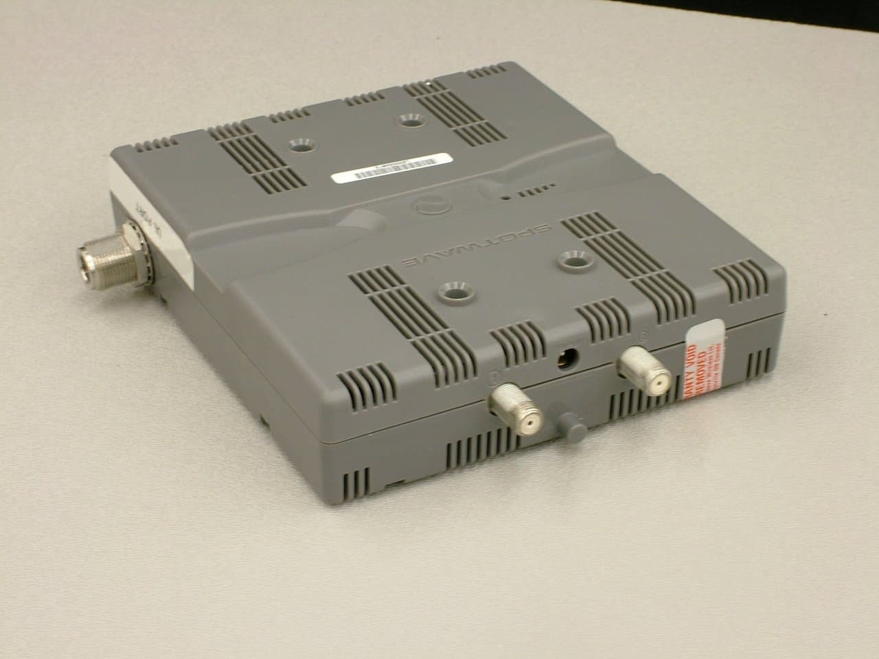
Click to zoom
Application Details
- Equipment Class
- TNB - Licensed Non-Broadcast Station Transmitter
- Date of Grant
- Jun 05, 2012
- Application Purpose
- Original Equipment
- Date of Application
- Jun 05, 2012
- Equipment Note
- SpotCell 2500 XI
- Frequency Range
- 746.00000000 - 757.00000000
- Company
- Spotwave Wireless Ltd.
- Country
- Canada
Documents & Files
Document Text
Text extracted from the exhibit documents filed with the FCC. Open a document above to read the original.
Users Manual
SpotCell ® 2500Xl User Manual Technical Support SpotCell ® serial numbers must be available to authorize technical support and/or to establish a return authorization for defective units. The serial numbers are located on the back of the Coverage Unit (CU) and the Donor Unit (DU), as well as on the box in which they were delivered. Additional support information may be obtained by accessing the Spotwave Wireless Inc. website at www.spotwave.com. To contact support by telephone, call your local Spotwave vendor; or if you are unable to reach your vendor, contact Spotwave Wireless at 866-704-9750. Important Safety Information Warning! For your safety, beware of power lines and ensure appropriate safety measures are maintained at all times during the installation of the SpotCell equipment. If equipment not shipped with the SpotCell system is to be used during installation or mounting, follow all equipment manufacturer’s instructions in proper use to ensure injury is avoided. The DU and CU of the SpotCell are low power transmitters. As with a cell phone antenna, avoid unneccessary contact with the front of the units when they units are operating. Mount the units in a location where people will not approach within 1 meter of the front of the DU and 20 centimeters in front of the CU. When deploying the extended coverage antenna, there must be a minimum separation of 10 cm between the main CU and the extended coverage antenna with the antennas facing in opposite directions. The extended coverage antenna should be mounted in locations where people will not approach within 20 cm in front of the antenna. This manual outlines installation instructions and the appendix offers practical safety tips (see Appendix E entitled ‘Safety Hints’). If you are not sure about a safe installation, do not attempt to install it yourself. Call a professional installer for help. LIMITED WARRANTY AND LIMITATION OF LIABILITY: 1. What is Covered and for How Long? Spotwave Wireless Inc. ("Spotwave") warrants to the original Purchaser that the Spotwave SpotCell System (the "System") is free from defects in material and workmanship under normal use and service for a period of 12 months from the date of shipment from Spotwave (the "Limited Warranty Period"). 2. What is not covered? This Limited Warranty is conditioned upon proper use of the System by the Purchaser. This Limited Warranty does not cover (and will become null and void in the event of): (a) defects or damage resulting from accident, misuse, abuse, neglect, unusual physical, electrical or electromechanical stress, modification of the System or any part thereof, or cosmetic damage; (b) removal, alteration or defacing of the serial number or other identifying marks on the System; (c) all plastic surfaces and other externally exposed components that are scratched or damaged due to normal use; (d) malfunctions resulting from the use of the System in conjunction with accessories, products or (ancillary) or peripheral equipment not provided by Spotwave; or (e) defects or damage from unauthorized or improper testing, operation, maintenance, installation, servicing or adjustment of the System. Any repairs or replacements provided by Spotwave outside of the Limited Warranty Period (including repairs to or replacement after the end of the Warranty Period), or in excess of the services provided during the Limited Warranty Period, will subject to Spotwave's then prevailing rates. 3. What are Spotwave's Obligations and how do you make a claim? During the Limited Warranty Period, Spotwave will repair or replace, at Spotwave's sole option, without charge to Purchaser, any defective component of the System, provided that the System is returned promptly upon discovery of the defect and during the Limited Warranty Period. To obtain service, Systems must be returned to an authorized service facility in the original packaging or packaging adequate for shipping, accompanied by Purchaser's sales receipt or comparable substitute proof of sale showing the date of purchase and the serial number of the System. A valid RMA is required prior to any return. To locate your nearest authorized service facility, call Spotwave Customer Service at 1-866-704-9750. Spotwave may, at Spotwave's sole option, use rebuilt, reconditioned, or new parts or components when repairing any System or replace a System with a rebuilt, reconditioned or new System. Repaired Systems LIMITED WARRANTY AND LIMITATION OF LIABILITY: will be warranted for a period equal to the remainder of the original Limited Warranty Period for the original System or for 90 days, whichever is longer. All replaced parts, components, boards or equipment shall become the property of Spotwave. If Spotwave determines that any System is not covered by this Limited Warranty, Purchaser must pay the costs for all parts, shipping, and labor charges for the repair or return of such System. 4. What are the Limits on Spotwave's Liability? EXCEPT FOR THE WARRANTY IN PARAGRAPH 1, THE SYSTEMS AND ANY ASSOCIATED SERVICES ARE PROVIDED BY SPOTWAVE ON AS 'AS IS' BASIS AND THERE ARE NO OTHER REPRESENTATIONS, WARRANTIES OR CONDITIONS, EXPRESS OR IMPLIED, WRITTEN OR ORAL, ARISING BY STATUTE, OPERATION OF LAW, COURSE OF DEALING, USAGE OF TRADE OR OTHERWISE, REGARDING THEM OR ANY OTHER PRODUCT OR SERVICE PROVIDED HEREUNDER OR IN CONNECTION HEREWITH BY SPOTWAVE. SPOTWAVE DISCLAIMS ANY IMPLIED WARRANTIES OR CONDITIONS OF DURABILITY, MERCHANT ABILITY, MERCHANTABLE QUALITY, SATISFACTORY QUALITY, NON-INFRINGEMENT OR FITNESS FOR A PARTICULAR PURPOSE. SPOTWAVE DOES NOT REPRESENT OR WARRANT THAT THE SYSTEMS WILL MEET ANY OR ALL OF PURCHASERS' PARTICULAR REQUIREMENTS, THAT THE SYSTEMS WILL OPERATE ERROR-FREE OR UNINTERRUPTED OR THAT ALL ERRORS OR DEFECTS IN THE SYSTEMS CAN BE FOUND TO BE CORRECTED. System performance is dependant upon the performance and availability of services or technology provided by third parties and Spotwave is not responsible for service continuit…
Text truncated - open the document above for the full version.
RF Exposure Info
731 Enterprise Drive Lexington, KY 40510 Telephone: 859-226-1000 Facsimile: 859-226-1040 www.intertek-etlsemko.com MPE Calculation § 1.1310: The criteria listed in table 1 shall be used to evaluate the environmental impact of human exposure to radiofrequency (RF) radiation as specified in §1.1307(b), except in the case of portable devices which shall be evaluated according to the provisions of §2.1093 of this chapter. Part 1.1310 Limits for Maximum Permissible Exposure (MPE) 731 Enterprise Drive Lexington, KY 40510 Telephone: 859-226-1000 Facsimile: 859-226-1040 www.intertek-etlsemko.com 1.1 Test Procedure An MPE evaluation for was performed in order to show that the device was compliant with §2.1091. The maximum power density was calculated for each transmitter at a separation distance of 20cm. For each transmitter the maximum RF exposure at a 20 cm distance using the formula: 10/)( 10 dBmowerConductedP mW PowerConducted= 2 )20(4 . cm mW GainAntPowerConducted tyPowerDensi × × = π 1.2 Results: The device meets the RF exposure limit at a 20cm separation distance as required by part 2.1091 of the FCC rules Measured Conducted Power = 6.1dBm Antenna Gain = 2dB Radiated Power = 6.1dBm + 2dB = 8.1dBm or 6.4mW Power Density= 6.4mW / 5025.6cm^2 = 0.001mW/cm^2 Limit at 20cm for 746MHz = 746 / 1500 = 0.497 mW/cm^2
Test Report
This report is for the exclusive use of Intertek's Client and is provided pursuant to the agreement between Intertek and its Client. Intertek's responsibility and liability are limited to the terms and conditions of the agreement. Intertek assumes no liability to any party, other than to the Client in accordance with the agreement, for any loss, expense or damage occasioned by the use of this report. Only the Client is authorized to permit copying or distribution of this report and then only in its entirety. Any use of the Intertek name or one of its marks for the sale or advertisement of the tested material, product or service must first be approved in writing by Intertek. The observations and test results in this report are relevant only to the sample tested. This report by itself does not imply that the material, product, or service is or has ever been under an Intertek certification program. EMC Report for «Company» on the «EUTName» Page 1 of 35 731 Enterprise Drive Lexington, KY 40510 Telephone: 859-226-1000 Facsimile: 859-226-1040 www.intertek-etlsemko.com TEST REPORT Report Number: 100649603LEX-002 Project Number: G100649603 Report Issue Date: 2/23/2012 Model: SpotCell 2500X1 Coverage Unit FCCID (Coverage Unit): P3YSPOTCELL0102 Standards: FCC Title 47 Part 27 Subpart C Tested by: Client: Intertek Testing Services NA, Inc. 731 Enterprise Drive Lexington, KY 40510 Spotwave Wireless Ltd. 500 Van Buren Street Kemptville ON K0G 1J0 Report prepared by Report reviewed by Bryan Taylor, Team Leader Jason Centers, Senior Project Engineer Intertek Report Number: «ReportNo» Issued: «ReportDate» EMC Report for «Company» on the «EUTName» FCCID:«FCCID»«ICID» Page 2 of 35 TABLE OF CONTENTS 1 Introduction and Conclusion .............................................................................................................. 3 2 Test Summary ...................................................................................................................................... 3 3 Description of Equipment Under Test ............................................................................................... 4 4 Conducted Output Power .................................................................................................................... 6 5 Occupied Bandwidth ........................................................................................................................... 8 6 Conducted Spurious Emissions at Antenna Terminals ................................................................. 13 7 Radiated Spurious Emissions (Transmitter) ................................................................................... 30 8 Measurement Uncertainty ................................................................................................................. 34 9 Revision History ................................................................................................................................. 35 Intertek Report Number: «ReportNo» Issued: «ReportDate» EMC Report for «Company» on the «EUTName» FCCID:«FCCID»«ICID» Page 3 of 35 1 Introduction and Conclusion The tests indicated in section 2 were performed on the product constructed as described in section 3. The remaining test sections are the verbatim text from the actual data sheets used during the investigation. These test sections include the test name, the specified test method, a list of the actual test equipment used, documentation photos, results and raw data. No additions, deviations, or exclusions have been made from the standard(s) unless specifically noted. Based on the results of our investigation, we have concluded the product tested complied with the requirements of the standard(s) indicated. The results obtained in this test report pertain only to the item(s) tested. All testing was performed at the Intertek located at 731 Enterprise Drive, Lexington Kentucky, 40510. The radiated emission test site is a 10-meter semi-anechoic chamber. The chamber meets the characteristics of CISPR 16-1 and ANSI C63.4. For measurements, a remotely controlled flush-mount metal-top turntable is used to rotate the EUT a full 360 degrees. A remote controlled non-conductive antenna mast is used to scan the antenna height from one to four meters. The test site is listed with the FCC under registration number 485103. The test site is listed with Industry Canada under site number IC 2042M-1. 2 Test Summary Page Test full name FCC Reference Result 6 Conducted Output Power §2.1046 & §27.50 Pass 8 Occupied Bandwidth §2.1049 Pass 13 Conducted Spurious Emissions §2.1049, §2.1051, § 27.53(c), & § 27.53(f) Pass 30 Radiated Spurious Emissions (Transmitter) §2.1053 and § 27.53(c) Pass - Frequency Stability §2.1055 Not Required 1 1 The device does not translate frequency. Intertek Report Number: «ReportNo» Issued: «ReportDate» EMC Report for «Company» on the «EUTName» FCCID:«FCCID»«ICID» Page 4 of 35 3 Description of Equipment Under Test Equipment Under Test Manufacturer Spotwave Wireless Ltd. Model Number SpotCell 2500X1 CoverageUnit Serial Number Test Sample 1 FCC Identifier (Coverage Unit) P3YSPOTCELL0102 Receive Date 2/3/2012 Test Start Date 2/3/2012 Test End Date 2/14/2012 Device Received Condition Good Test Sample Type Prototype Frequency Band 746MHz - 757MHz (Upper Block - Downlink) Modulation Type LTE (OFDMA) Transmission Control Signal Generator Maximum Output Power (Conducted) 5.89 dBm (Upper Block - Downlink) Antenna Type External, User provided Operating Voltage 120VAC Test Channels / Frequencies Low: 746MHz Upper Block Downlink Mid: 751MHz High: 756MHz Description of Equipment Under Test The test sample was a cell booster device manufactured by Spotwave Wireless Ltd. The coverage units install indoors and the donor units install outdoors. Together they allow for increased wireless signal strength inside office buildings or in other areas where wireless dead spots occur. Operating modes of the EUT: No. Descriptions of EU…
Text truncated - open the document above for the full version.
Contact Information
Applicant
Jay R Sengupta(Engineering Manager)
Test Firm
Intertek Testing Services NAJames Sudduth
Technical Specifications
| # | Rule Parts | Frequency Range | Power Output | Emission | Tolerance |
|---|---|---|---|---|---|
| 4 | 27 | 746 MHz - 757 MHz | 3.80 mW | 8M9W7D | Amp |
Other Applications from Spotwave Wireless Ltd.
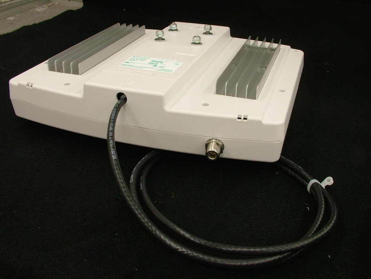
P3YSPOTCELL0101
Jun 05, 2012SpotCell 2500 XI
Equipment Class
TNB - Licensed Non-Broadcast Station Transmitter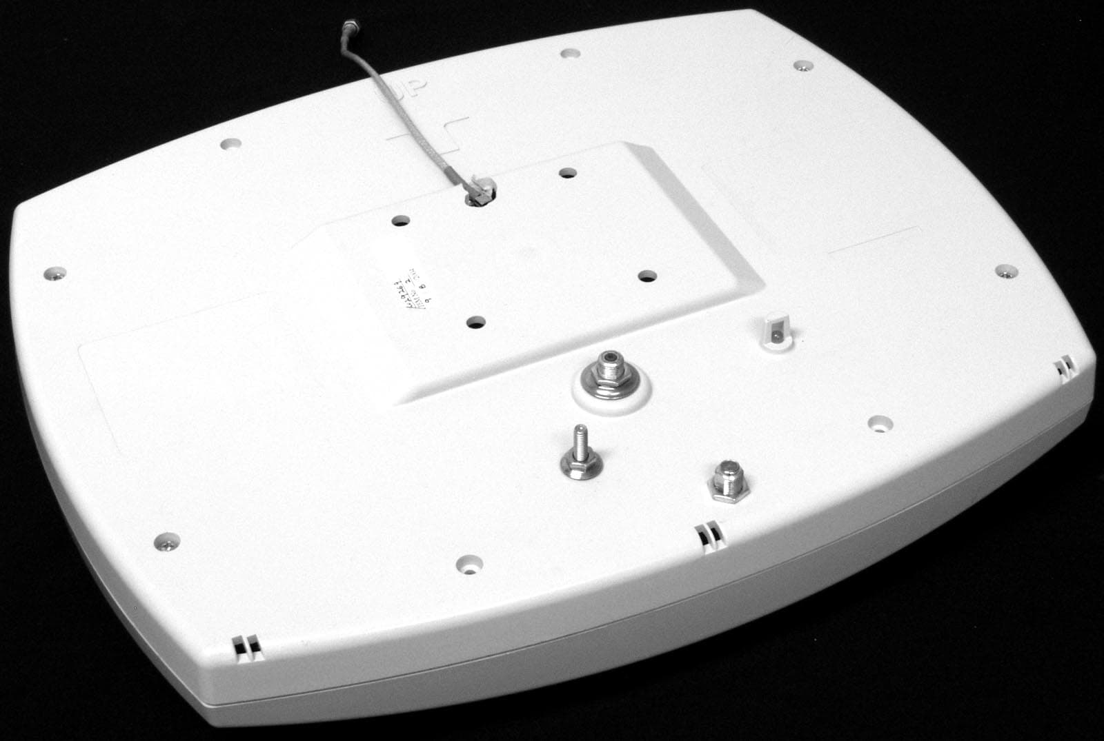
P3YSPOTCELL0013
Nov 02, 2004DU 1900 Full Band
Equipment Class
PCB - PCS Licensed Transmitter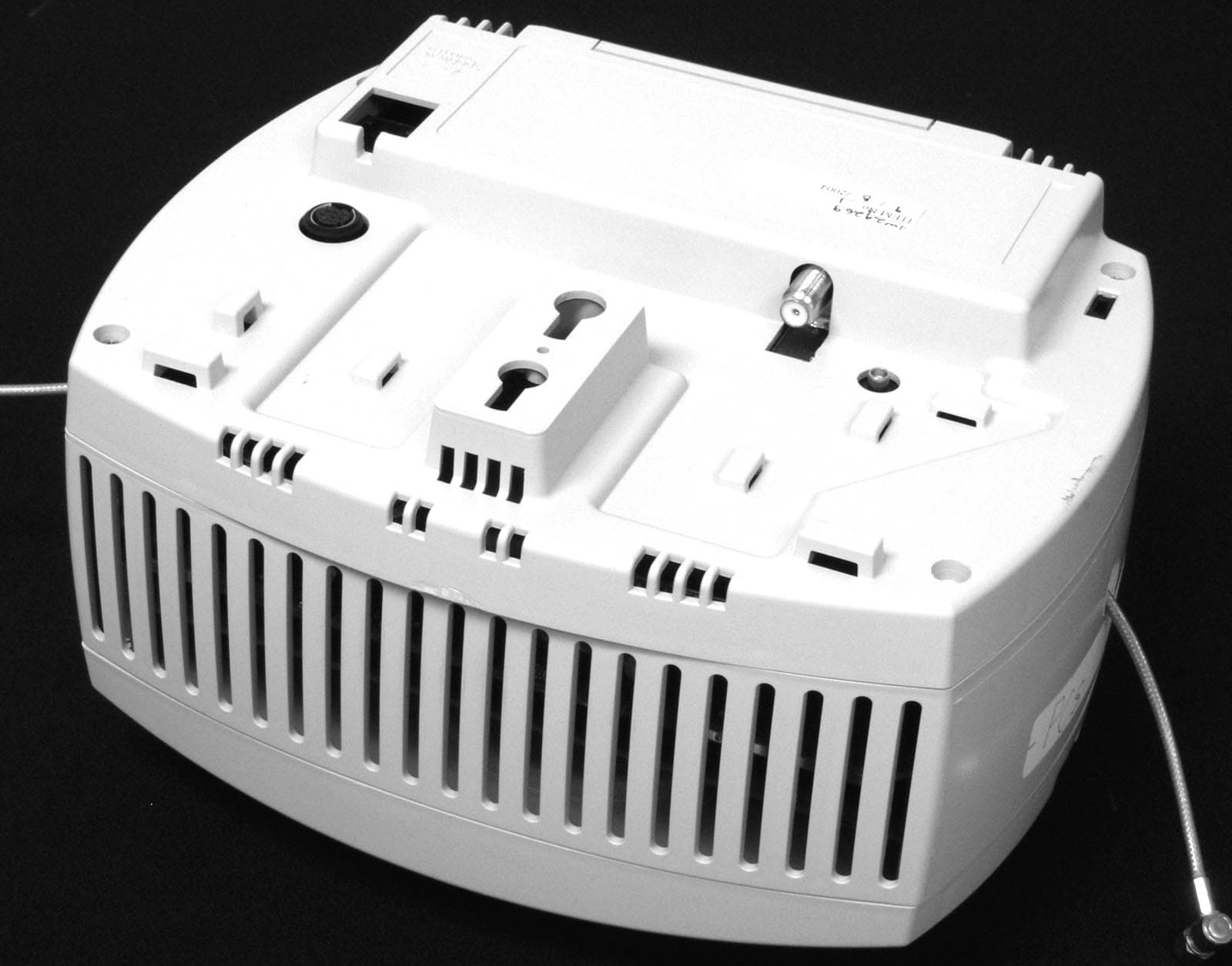
P3YSPOTCELL0012
Nov 02, 2004Cell enhancer
Equipment Class
PCB - PCS Licensed Transmitter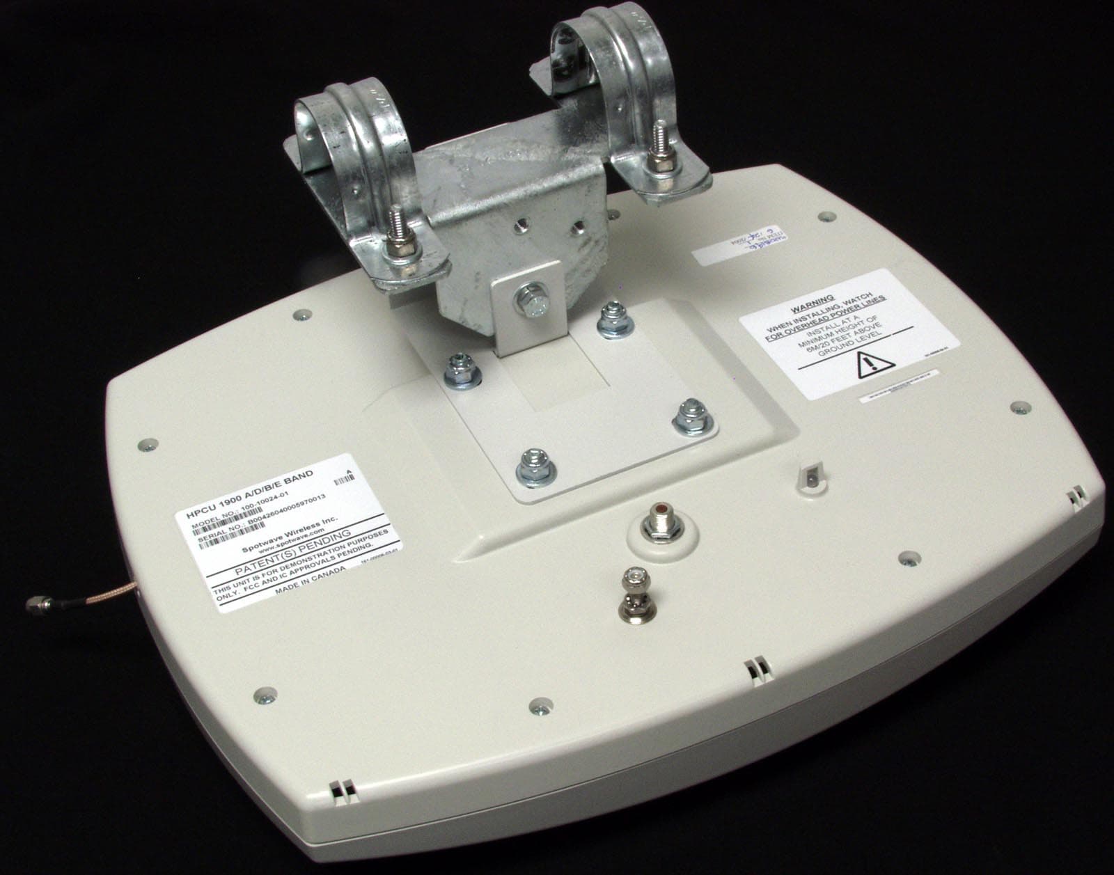
P3YSPOTCELL0011
Aug 30, 2004Spotcell 612
Equipment Class
PCB - PCS Licensed Transmitter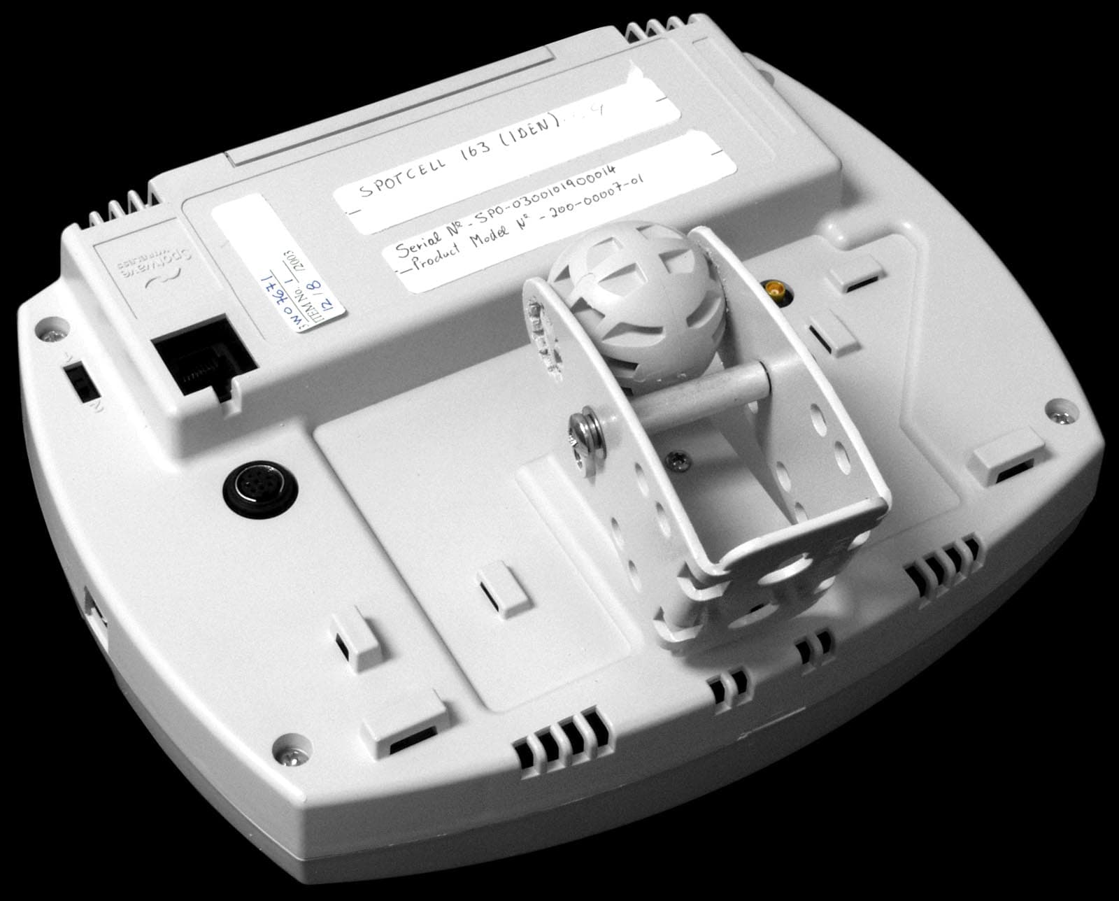
P3YSPOTCELL0009
Feb 04, 2004Spotcell 163 IDEN DU
Equipment Class
AMP - Amplifier