P4M-EMIVCDMA External Data Modem
AnyDATA Corporation
Click to zoom
Application Details
- Equipment Class
- PCB - PCS Licensed Transmitter
- Date of Grant
- Sep 22, 2004
- Application Purpose
- Original Equipment
- Date of Application
- Sep 22, 2004
- Equipment Note
- CDMA External Data Modem
- Frequency Range
- 824.00000000 - 849.00000000
- Company
- AnyDATA Corporation
- Country
- United States
Documents & Files
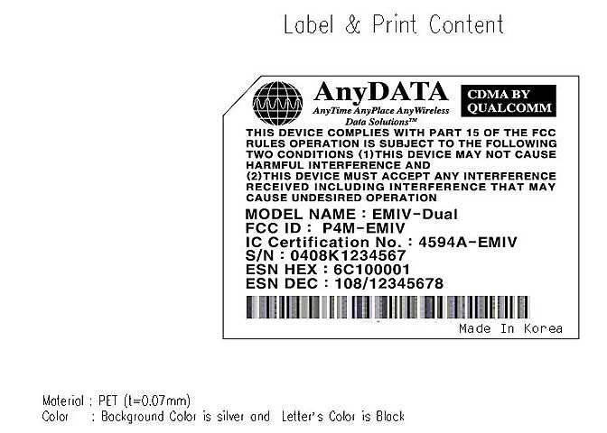
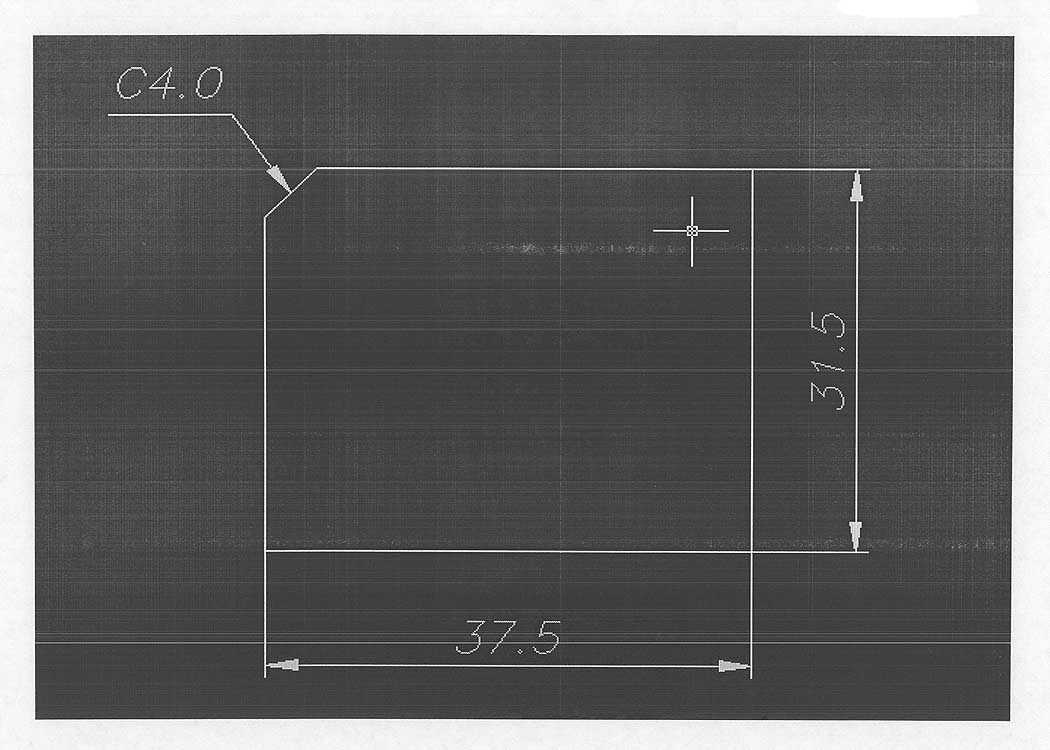
Document Text
Text extracted from the exhibit documents filed with the FCC. Open a document above to read the original.
Users Manual
EMIV-DUAL V1.0 AnyDATA.NET Proprietary – Use Subject to Restrictions EMIV-DUAL User Manual Application Information 01-EMIVDUAL-1_X1 June 29, 2004 AnyDATA.NET Inc. Hanvit Bank B/D 6F Byulyang-dong Kwachon KOREA Tel) 82-2-504-3360 Fax) 82-2-504-3362 Interface Description EMIV-DUAL Reference Manual Application Information EMIV-DUAL V1.0 AnyDATA.NET Proprietary – Use Subject to Restrictions AnyDATA.NET Inc. Hanvit Bank B/D 6F Byulyang-dong Kwachon KOREA Copyright ⓒ 2001 AnyDATA.NET Inc.. All rights reserved. Printed in the Republic Of KOREA. All data and information contained in or disclosed by this document are confidential and proprietary information of AnyDATA.NET Inc., and all rights therein are expressly reserved. By accepting this material, the recipient agrees that this material and the information contained therein are held in confidence and in trust and will not be used, copied, reproduced in whole or in part, nor its contents revealed in any manner to others without the express written permission of AnyDATA.NET Inc.. AnyDATA.NET Proprietary: Restricted Distribution. This document contains critical information about AnyDATA.NET products and may not be distributed to anyone without permission of AnyDATA.NET Inc. All data and information contained in this document are proprietary and confidential information of AnyDATA.NET Inc. No part of this document may be reproduced, in any form or any means without written permission of AnyDATA.NET Inc. Although the information in this document has been carefully reviewed and its believed to be reliable. AnyDATA.NET Inc. does not assume any liability arising out of the application or use of any product described herein, Neither does it convey any license under its patent rights nor rights of others. Send Technical Questions to : [email protected] EMIV-DUAL Reference Manual Application Information 01-EMIVDUAL-1_X1 June 29, 2004 Interface Description EMIV-DUAL Reference Manual Application Information EMIV-DUAL V1.0 AnyDATA.NET Proprietary – Use Subject to Restrictions Introduction The EMIV-DUAL is designed for the test and simulation of the CDMA wireless data communications. User can connect the EMIV-DUAL to your PC or Notebook and easily test the wireless communications. User can use this to develop your applications software even before user’s own hardware is ready. It also can be used as a debugging during user’s hardware test. Disclaimer and Limitation of Liability AnyDATA.NET Inc. assumes no responsibility for any damage or loss resulting from the misuse of its products. AnyDATA.NET Inc. assumes no responsibility for any loss or claims by third parties, which may arise through the use of its products. AnyDATA.NET Inc. assumes no responsibility for any damage or loss caused by the deletion or loss of data as a result of malfunctions or repairs. The information disclosed herein is the exclusive property of AnyDATA.NET Inc. and no part of this publication may be reproduced or transmitted in any form or by any means including electronic storage, reproduction, execution or transmission without the prior written consent of AnyDATA.NET Inc. The information contained in this document is subject to change without notice. Reproduction, adaptation or translation of this document is prohibited without prior written permission of AnyDATA.NET Inc. Interface Description EMIV-DUAL Reference Manual Application Information EMIV-DUAL V1.0 AnyDATA.NET Proprietary – Use Subject to Restrictions FCC RF Exposure Information Warning! Read this information before using this device. In August 1996 the Federal Communications Commission (FCC) of the United States with its action in Report and Order FCC 96-326 adopted an updated safety standard for human exposure to radio frequency electromagnetic energy emitted by FCC regulated transmitters. Those guidelines are consistent with the safety standard previously set by both U.S. and international standards bodies. The design of this device complies with the FCC guidelines and these international standards. CAUTION Operating Requirements The user can not make any changes or modifications not expressly approved by the party responsible for compliance, otherwise it could void the user's authority to operate the equipment. To satisfy FCC RF exposure compliance requirements for a mobile transmitting device, this device and its antenna should generally maintain a separation distance of 20cm or more from a person’s body. Antenna Gain must not exceed 1dBi Special accessories In order to ensure this device in compliance with FCC regulation, the special accessories are provided with this device and must be used with the device only. The user is not allowed to use any other accessories than the special accessories given with this device Interface Description EMIV-DUAL Reference Manual Application Information EMIV-DUAL V1.0 AnyDATA.NET Proprietary – Use Subject to Restrictions Contents 1 Introduction 1.1 Purpose 1.2 Organization 1.3 Revision History 2 Overview 2.1 Application Description 2.2 Technical Specifications 2.2.1 General Specification 2.2.2 Receive Specification 2.2.3 Transmit Specification 2.2.4 gpsOne Receiver Specification 2.2.5 Standards 2.3 Interface Diagram 2.4 EMIV-DUAL General Features 2.5 Internal Modem Features 3 PIN Description 3.1 8-Pin Connector (RS232 Standard) 3.2 3-Pin Connector (Debugging) 3.3 DC Power Connector Interface Description EMIV-DUAL Reference Manual Application Information EMIV-DUAL V1.0 AnyDATA.NET Proprietary – Use Subject to Restrictions 4 Interface Descriptions 4.1 Overview 4.2 RS232 Interface (Standard) 5 Electrical Specifications 5.1 Absolute Maximum Ratings 5.2 Recommended Operating Conditions 5.3 Power Consumption 5.4 Serial Interface Electrical Specifications 6 Mechanical Dimension 6.1 EMIV-DUAL Outline 7 FCC Notice 8 Installation Example Interface Description EMIV-DUAL Reference Manual Application Information EMIV-DUAL V1.0 AnyDATA.NET Proprietary – Use Subject to Restrictions 1. Introdu…
Text truncated - open the document above for the full version.
Cover Letter(s)
Response to E04-000075-1 1. At the time I filed the application the address of the applicant was that which is on the 731 form. Since that time, the applicant has changed the contact and address information. Please use the most recent information for the grant. 2. The upload website does not ask the address of the manufacturer. Item 2 as it was uploaded was the correct applicant at the time of the application, but has been changed in the meantime by the applicant. 3. The correct FRN number is 005-8652-25. The TCB website has been corrected. 4. The output power on the 731 form for 824-849 MHz should have been 0.4074 Watts. The output power for 1851.25-1908.75 MHz was correctly listed as 0.6792 Watts. 5. Page 9 of the test report has been revised to answer this question. 6. The test report has been revised on page 39 to reflect an output power of 0.6792 Watts, which matches the 731 form and page 6. The 731 form should have listed the output power for 824-849 MHz as 0.4074 Watts which matches page 6. Revised MPE calculations have been uploaded to correct that area. 7. The 731 form should state the maximum frequency devation for the 1900MHz range as .00020%. Response to E04-000075-2 1. The test report has been revised to show the frequency devision in ppm. The 731 form should show it at 1.57838 ppm for Part 22 and 2.0 for Part 24. The ANSI/TIA/EIA/603-A-2001 antenna substitution method was used.
External Photos
Front Top Bottom Side 1 Side 2
Internal Photos
PCB Front PCB Back RF PCB Front RF PCB Back RF Section Frong RF Section Back
Operational Description
DC Voltages - 81953 Input Vtg range: 7V to 16V, Current consumtion at 12V: 350mA
Operational Description
Technical Specification & description 1. General Feactures - CDMA 2000 1xRTT - IS-95A/B/C - Standard RS-232E interface - Data transmission up to 153Kbps - Remote control by AT command - Built-in TCP/IP/UDP stack - 2-way SMS - Voice, Enhanced variable rate codec (EVRC) - Quick Net Connect for fast Internet connection - Telemetry-specific features - Optimized for easy OEM applications - Supports Circuit Data/Fax 2 Technical Specifications 2.1 General Specifications PARAMETERS DESCRIPTIONS External Access Code-Division-Multiple-Access (CDMA) CDMA Protocol IS-95 A/B, IS-126, IS-637A, IS-707A, IS-2000 Data Rate 153.6Kbps Transmit/Receive Frequency Interval 45MHz for Cellular and 80MHz for PCS Band Width 1.23MHz Operating Voltage DC 7V ~ 16V Current Consumption Sleep mode : 30mA, Idle mode (70mA) , Traffic mode : 350mA (Max) at 12V Operating Temperature -30°C ~ +60°C Frequency Stability ±300Hz for 800MHz CDMA and ±150Hz for 1900MHz CDMA Antenna Magnet mount helical antenna, 50ohm, 1dBi Gain for 800MHz and 1900MHz, -4dBi for 1575MHz Size 60 X 112 X 29mm Weight About 110g External Interface RS-232, Analog audio, Power, Antenna, Debug port 2.2 Receive Specifications PARAMETERS DESCRIPTIONS Frequency Range 869.04 ~ 893.97 MHz for 800MHz CDMA and 1931.25 ~ 1988.75MHz for 1900MHz CDMA Sensitivity Below –104dBm Interference Rejection Single tone (-30dBm @900KHz): Below –101dBm for 800MHz Single tone (-30dBm @1250KHz): Below –101dBm for 1900MHz Spurious Wave Suppression Below –80dBc Input Dynamic Range -25dBm ~ -104dBm 2.3 Transmit Specifications PARAMETERS DESCRIPTIONS Frequency Range 824.04 ~ 848.97 MHz for 800MHz CDMA and 1851.25 ~ 1908.75MHz for 1900MHz CDMA Nominal Max. Power 0.32 W (24.7dBm) Peak Power in Operation Mode 0.35W (25.5dBm) Minimum Controlled Output Power Below –50dBm Max Power Spurious 900KHz: Below –42dBc/30KHz 1.98MHz: Below –54dBc/30KHz 1250KHz : Below –42dBc/30KHz 1.98MHz: Below –50dBc/30KHz 2.4 Serial Interface Electrical Specifications PARAMETER MIN MAX UNITS Input High Voltage +2 +15 V Input Low Voltage -15 -2 V Output High Voltage +5 +7 V Output Low Voltage -7 -5 V 2.5 gpsOne Receiver Specifications Parameters Descriptions Frequency Range L1, 1575.42MHz C/A Code 1.023MHz Chip Rate Receiver Sensitivity -152dBm 3 Standards IS-95 A/B: Protocol Between MS & BTS IS-96A: Voice Signal Coding IS-98A: Base MS Function IS-126: Voice Loop-Back IS-637: Short Message Service IS-707: Data Service Built-in TCP/IP : AnyDATA proprietary software IS-657 : packet data
Operational Description
AnyDATA.NET APPROVAL SHEET ITEM : HW - 3BM - SMA FREQUENCY : TRIPLE MAGNET-ANTENNA FOR CDMA/USPCS/GPS HANUL Technology TEL. : 032) 678-8614 032)678-8610 FAX. : 032) 678-8615 ANTENNA SPECITICATION 1. ITEM : HW-3BM-SMA 2. Electrical Specifications No. ELECTRICAL DATA SPECIFICATIONS REMARK AMPS 824MHz-894MHz GPS 1575MHz 2.1 RESONANCE FREQUENCY UPPCS 1850MHz-1990MHz 2.2 IMPEDANCE 50Ω NOMINAL CDMA +1dBi GPS -4dBi 2.3 GAIN USPCS +1dBi Peak 2.4 ELECTRICAL LENGTH 1/4λ 2.5 RADIATION PATTERN OMNI – DIRECTIONAL 2.6 POLARIZATION VERTICAL 3. Mechanical Specifications No. MECHANICAL SPECIFICATIONS REMARK 3.1 ELEMENT Ø0.5-PWG Ni-PLATING 3.2 SLEEVE URETHANE BLACK-COLOR 3.3 COVER ABS BLACK-COLOR 3.4 CONNECTOR SMA(Male) GOLD- PLATING 3.5 TOTAL LENGTH 85 ± 2.0 mm 4. Antenna Configuration 한울 한울테크놀로지 5. Measurement Result CH1MEMLOG3 dB/REF 0 dB START600 . 000000MHzSTOP2 200 . 000000MHz HW-3BM-SMA MARKER 5 1.99 GHz 15 Jun 2004 22:47:53 1 2 3 4 5 5 : -11. 054dB1 990 . 000000MHz CH1Markers 1 : -12. 557dB 824 . 000MHz 2 : -12. 679dB 894 . 000MHz 3 : -8 . 9691dB 1 . 57500GHz 4 : -12. 786dB 1 . 85000GHz MARKER PARAMChannel1Channel2Channel3Channel4 MARKER 1824 . 000000MHz0. 000000MHz0. 000000MHz0 . 000000MHz -12 . 557dBOFFOFFOFF MARKER 2894 . 000000MHz0. 000000MHz0. 000000MHz0 . 000000MHz -12 . 679dBOFFOFFOFF MARKER 31575 . 000000MHz0. 000000MHz0. 000000MHz0 . 000000MHz -8 . 9691dBOFFOFFOFF MARKER 41850 . 000000MHz0. 000000MHz0. 000000MHz0 . 000000MHz -12 . 786dBOFFOFFOFF MARKER 51990 . 000000MHz0. 000000MHz0. 000000MHz0 . 000000MHz -11 . 054dBOFFOFFOFF MKR STIM OFFSET0 . 000000MHz0. 000000MHz0. 000000MHz0 . 000000MHz 0 dB0 dB. 0000dB0 dB REFERENCE MARKEROFFOFFOFFOFF PLACEMENTCONTINUOUSCONTINUOUSCONTINUOUSCONTINUOUS MARKER SEARCHOFFOFFOFFOFF TARGET VALUE-3dB-3dB-3dB-3dB MKR WIDTH VALUE-3dB-3dB-3dB-3dB OFFOFFOFFOFF MARKER TRACKINGOFFOFFOFFOFF SMOOTH APERTURE1 % SPAN1 % SPAN1 % SPAN1 % SPAN OFFOFFOFFOFF PHASE OFFSET0 000 ELECTRICAL DELAY0 s0 s0 s0 s CH1MEMSWR1 /REF 1 START600 . 000000MHzSTOP2 200 . 000000MHz HW-3BM-SMA MARKER 5 1.99 GHz 15 Jun 2004 22:48:27 1 2 3 4 5 5 : 1 . 77971 990 . 000000MHz CH1Markers 1 : 1 . 6163 824 . 000MHz 2 : 1 . 6068 894 . 000MHz 3 : 2 . 1059 1 . 57500GHz 4 : 1 . 5957 1 . 85000GHz MARKER PARAMChannel1Channel2Channel3Channel4 MARKER 1824 . 000000MHz0. 000000MHz0. 000000MHz0 . 000000MHz 1 . 6163OFFOFFOFF MARKER 2894 . 000000MHz0. 000000MHz0. 000000MHz0 . 000000MHz 1 . 6068OFFOFFOFF MARKER 31575 . 000000MHz0. 000000MHz0. 000000MHz0 . 000000MHz 2 . 1059OFFOFFOFF MARKER 41850 . 000000MHz0. 000000MHz0. 000000MHz0 . 000000MHz 1 . 5957OFFOFFOFF MARKER 51990 . 000000MHz0. 000000MHz0. 000000MHz0 . 000000MHz 1 . 7797OFFOFFOFF MKR STIM OFFSET0 . 000000MHz0. 000000MHz0. 000000MHz0 . 000000MHz 00 dB. 0000dB0 dB REFERENCE MARKEROFFOFFOFFOFF PLACEMENTCONTINUOUSCONTINUOUSCONTINUOUSCONTINUOUS MARKER SEARCHOFFOFFOFFOFF TARGET VALUE-3-3dB-3dB-3dB MKR WIDTH VALUE-3-3dB-3dB-3dB OFFOFFOFFOFF MARKER TRACKINGOFFOFFOFFOFF SMOOTH APERTURE1 % SPAN1 % SPAN1 % SPAN1 % SPAN OFFOFFOFFOFF PHASE OFFSET0 000 ELECTRICAL DELAY0 s0 s0 s0 s
Parts List/Tune Up Info
Tune up procedure To set up transmit power before shipping, AnyDATA uses a manufacturing process which is called “Calibration of Rx and Tx power over the dynamic range, temperature and frequency”. CDMA technical standard requires AnyDATA’s CDMA module to transmit more than +23dBm output power when it is required to transmit its maximum power. Therefore, AnyDATA sets the maximum power of the module to +24.5dBm (+1dB, -1.5dB) By adjusting Tx AGC Amplifier built in the CDMA module, transmit power can be limited to +24.5dBm (+1dB,-1.5dB) Transmit power calibration consists of transmit linearizer calibration, and power compensation calibration over the temperature and frequency. During the transmit linearizer calibration, the module searches for 16 AGC adjust values for the 16 power levels within the dynamic range including the maximum output power and saves these AGC adjust values in the memory device in the module. These searched AGC adjust values (TX_LIN_MASTER) set the maximum power of the module. To prevent the variation in maximum power over the frequency, the transmit circuit is calibrated over the frequency and compensation values (TX_LIM_VS_FREQ) are found. These values are also used to limit the maximum output power to +24.5dBm (+1dB,-1.5dB) Also to prevent the variation in maximum power over the temperature, the transmit circuit is calibrated over the temperature and compensation values (TX_LIM_VS_TEMP) are found. These are also used to limit the maximum output power to +24.5dBm (+1dB,-1.5dB) when there is variation in temperature..
RF Exposure Info
5473A Clouds Rest Road : Mariposa, CA 95338 : Phone 209-966-5420 : Fax 209-742-6133 Maximum Permissible Exposure Calculations Date of Report: 7/2/04 Calculations prepared for: John Kim AnyData.net Incorporated 18902 Bardeen Rd Irvine, CA 92612 Calculations prepared by: Eddie Wong 110 N. Olinda Place Brea, CA 9283 Model Number: EMIV- Dual FCC Identification: NA Fundamental Operating Frequency: 824.04- 848.97, 1851.25-1908.75 MHz Maximum Rated Output Power: +25.5 dBm (0.3548Watt) Conducted Measured Output Power: 836.52 MHz +26.1 dBm (0.4074Watt) EIRP Measured Output Power: 1880.00 MHz +28.3 dBm (0.6792Watt) EIRP MPE Limit in accordance with 1.1310(b): Limits for general population/uncontrolled exposure MPE Limit for 824.25-848.97 MHz = f /1500 mW/cm 2 = 1.25 mW/cm 2 ( 12.5W/m 2 ) MPE Limit for 1851.25-1908.75 MHz = 1 mW/cm 2 (10 W/m 2 ) Power Output (Watts) Power Density Limit (mW/cm 2 ) Minimum Distance (Meters) 0.6792 1 0.0532m 0.4074 1.25 0.0509m P t = Power Delivered to the Antenna G = Antenna Gain d = Distance in meters Zo = Impedance of Free Space The typical antennas to be used with the EUT are structure mount antenna which under normal operation has an antenna height of at least 0.2 meters (20 cm). As can be seen from the MPE result, this device passes the limit specified in 1.1310 at a distance of 0.0532and 0.0509 meter. Calculation: 0 2 t 2 x Zd G x P x 30 )(W/m Density Power= = 0.0532m =0.0509m 377 x 10 1 x 6792.0 x 30 d= 377 x 5.12 1 x 4074.0 x 30 d=
Test Report
Page 1 of 93 Report No.: FC04-054A ADDENDUM TO ANYDATA CORPORATION TEST REPORT FC04-054 FOR THE CDMA DUAL BAND MODEM, EMIV-DUAL FCC PART 15 SUBPART B SECTIONS 15.107 & 15.109 CLASS B, FCC PART 22 SUBPART H & PART 24 SUBPART E AND RSS 129 & 133 COMPLIANCE DATE OF ISSUE: SEPTEMBER 14, 2004 PREPARED FOR: AnyDATA Corporation 18902 Bardeen Ave. Irvine, CA 92612 PREPARED BY: Mary Ellen Clayton CKC Laboratories, Inc. 5473A Clouds Rest Mariposa, CA 95338 W.O. No.: 81938Date of test: June 24 - July 8, 2004 Report No.: FC04-054A This report contains a total of 93 pages and may be reproduced in full only. Partial reproduction may only be done with the written consent of CKC Laboratories, Inc. The results in this report apply only to the items tested, as identified herein. Page 2 of 93 Report No.: FC04-054A TABLE OF CONTENTS Administrative Information .............................................................................................3 Summary of Results .........................................................................................................4 Conditions for Compliance ..............................................................................................4 Approvals .........................................................................................................................4 Equipment Under Test (EUT) Description ......................................................................5 Equipment Under Test .....................................................................................................5 Peripheral Devices ...........................................................................................................5 Temperature and Humidity During Testing.....................................................................6 FCC 2.1033(c)(3) Userís Manual ....................................................................................6 FCC 2.1033(c)(4) Type of Emissions ..............................................................................6 FCC 2.1033(c)(5) Frequency Range................................................................................6 FCC 2.1033(c)(6) Operating Power.................................................................................6 FCC 2.1033(c)(7) Maximum Power Rating ....................................................................6 FCC 2.1033(c)(8) DC Voltages .......................................................................................6 FCC 2.1033(c)(9) Tune-Up Procedure ............................................................................6 FCC 2.1033(c)(10) Schematics and Circuitry Description..............................................6 FCC 2.1033(c)(11) Label and Placement ........................................................................6 FCC 2.1033(c)(12) Submittal Photos ..............................................................................6 FCC 2.1033(c)(13) Modulation Information ...................................................................6 FCC 2.1033(c)(14)/2.1046/22.913(a) - RF Power Output...............................................7 FCC 2.1033(c)(14)/2.1046/24.232(b) - RF Power Output ..............................................8 FCC 2.1033(c)(14)/2.1047(b) - Audio Frequency Response...........................................11 FCC 2.1033(c)(14)/2.1047(b) - Modulation Limiting Response.....................................11 FCC 2.1045 Occupied Bandwidth Part 22.......................................................................11 FCC 2.1045 Occupied Bandwidth Part 24.......................................................................14 Blockedge Plots Part 22 ...................................................................................................18 Blockedge Plots Part 24 ...................................................................................................20 FCC 2.1033(c)(14)/2.1051/22.917(a) - Spurious Emissions at Antenna Terminal .........23 FCC 2.1033(c)(14)/2.1051/24.238(a) - Spurious Emissions at Antenna Terminal .........28 FCC 2.1033(c)(14)/2.1053/22.917(a) - Field Strength of Spurious Radiation ...............32 FCC 2.1033(c)(14)/2.1053/24.238(a) - Field Strength of Spurious Radiation ................39 FCC 2.1033(c)(14)/2.1055/22.355(a)(d) - Frequency Stability.......................................45 FCC 2.1033(c)(14)/2.1055/24.235(a)(d) - Frequency Stability.......................................46 FCC 15.107 ñ AC Conducted Emissions.........................................................................48 FCC 15.109 ñ Radiated Emissions ..................................................................................74 RSS-129 99% Bandwidth ................................................................................................87 RSS-133 99% Bandwidth ................................................................................................90 Page 3 of 93 Report No.: FC04-054A ADMINISTRATIVE INFORMATION DATE OF TEST: June 24 - July 8, 2004 DATE OF RECEIPT: June 24, 2004 PURPOSE OF TEST: To demonstrate the compliance of the CDMA Dual Band Modem, EMIV-Dual with the requirements for FCC Part 15 Subpart B Sections 15.107 & 15.109, FCC Part 22 Subpart H & Part 24 Subpart E and RSS 129 & 133 devices. Addendum A is to revise the standard matrix on page 4, the RF power calculations on page 9 and the mid spurious emissions table on page 39. TEST METHOD: FCC Part 22 Subpart H & Part 24 Subpart E, ANSI C63.4 (2001) and RSS 212 FREQUENCY RANGE TESTED: 9 kHz-20 GHz MANUFACTURER: AnyDATA Corporation 18902 Bardeen Ave. Irvine, CA 92612 REPRESENTATIVE: John Kim TEST LOCATION: CKC Laboratories, Inc. 110 Olinda Place Brea, CA 92621 Page 4 of 93 Report No.: FC04-054A SUMMARY OF RESULTS As received, the AnyDATA Corporation CDMA Dual Band Modem, EMIV-Dual was found to be fully compliant with the following standards and specifications: Low Frequency High Frequency FCC Standard FCC Section Canadian…
Text truncated - open the document above for the full version.
Test Setup Photos
PHOTOGRAPH SHOWING DIRECT CONNECT TEST SETUP PHOTOGRAPH SHOWING DIRECT CONNECT TEST SETUP PHOTOGRAPH SHOWING RADIATED EMISSIONS Radiated Emissions - Front View PHOTOGRAPH SHOWING RADIATED EMISSIONS Radiated Emissions - Front View - Horn Antenna PHOTOGRAPH SHOWING RADIATED EMISSIONS Radiated Emissions - Back View PHOTOGRAPH SHOWING RADIATED EMISSIONS Radiated Emissions - Loop Antenna PHOTOGRAPH SHOWING TEMPERATURE TESTING PHOTOGRAPH SHOWING MAINS CONDUCTED EMISSIONS Mains Conducted Emissions - Front View PHOTOGRAPH SHOWING MAINS CONDUCTED EMISSIONS Mains Conducted Emissions - Side View
Contact Information
Applicant
Albert Shin(Head of Product)
Technical Contact
CKC Laboratories, Inc.MaryEllen Clayton
[email protected]209-966-5240
5473A Clouds Rest · Mariposa, California · United States
Non-Technical Contact
CKC Laboratories, Inc.MaryEllen Clayton
[email protected]209-966-5240
Test Firm
CKC Laboratories, Inc.Steve Behm
Technical Specifications
| # | Rule Parts | Frequency Range | Power Output | Emission | Tolerance |
|---|---|---|---|---|---|
| 2 | 22H | 824 MHz - 849 MHz | 407.40 mW | 1M29F9W | 1.58 ppm |
Other Applications from AnyDATA Corporation

P4M-ACT10
Oct 26, 2014OBD Vehicle Tracking Device
Equipment Class
DTS - Digital Transmission System
P4M-ACT613
Jun 22, 2014Vehicle Tracker
Equipment Class
DSC - Part 15 Security/Remote Control Transmitter
P4M-APT230
Nov 24, 2013CDMA Personal Tracking Device
Equipment Class
PCB - PCS Licensed Transmitter
P4M-ACT233
Jun 05, 20134G Vehicle Tracker with Hotspot
Equipment Class
PCB - PCS Licensed Transmitter
P4M-ACT210
Nov 27, 2012OBD-II Vehicle Tracking Device
Equipment Class
PCB - PCS Licensed Transmitter