P4MAGT100DCDMA Position reporting device
AnyDATA Corporation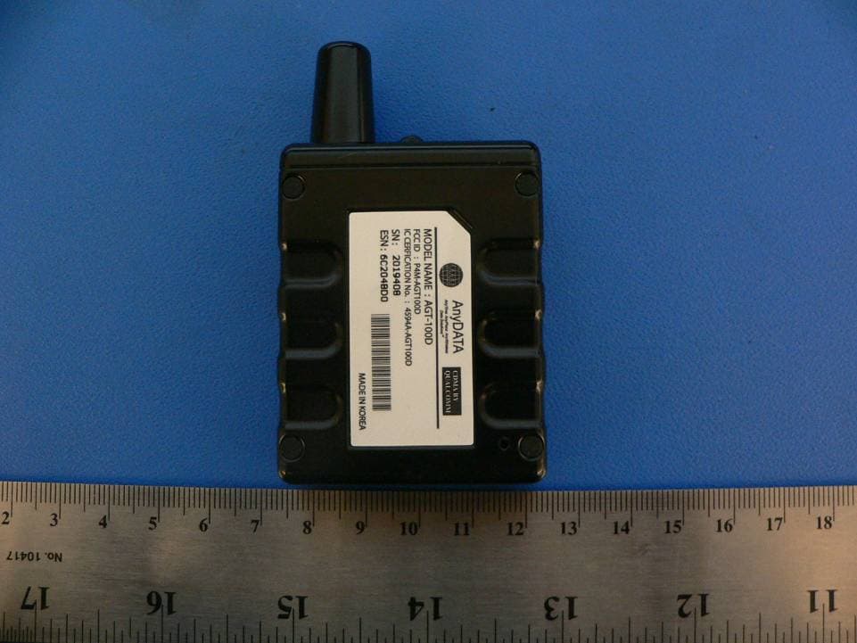
Click to zoom
Application Details
- Equipment Class
- PCB - PCS Licensed Transmitter
- Date of Grant
- Aug 24, 2006
- Application Purpose
- Original Equipment
- Date of Application
- Aug 24, 2006
- Equipment Note
- CDMA Position reporting device
- Frequency Range
- 824.70000000 - 848.30000000
- Company
- AnyDATA Corporation
- Country
- United States
Documents & Files
Document Text
Text extracted from the exhibit documents filed with the FCC. Open a document above to read the original.
Users Manual
Asset Tag Users Manual (AGT-100D) CDMA ASSET TAG Users Manual July, 2006 AGT-100D – v 1.3 AnyDATA AnyTime AnyPlace Any Wireless Data Solutions™ All Rights Reserved. 1/16 Asset Tag Users Manual (AGT-100D) AnyDATA CDMA AGT-100D Copyright © 2005 AnyDATA Corp. All Rights Reserved. Any part of this document may not be distributed, communicated, reproduced or transmitted in any form or by any means, electronic or mechanical or otherwise, for any purpose, without the permission of AnyDATA Corp. This document can be subjected to revision without further notice. Contact Address Headquarter AnyData Corporation 18902 Bardeen Ave, lrvine, CA 92612-1522 U.S.A. http://www.anydata.net e-mail: [email protected] Rep:1-949-833-0011 Fax: 1-949-833-0022 AnyData(China) 489 Song Tao Road, Sector B, 1st Fl. Pudong ZhanJiang Hi- Tech Park, Shanghai, 201203, P.R.China http://www.anydata.net.cn e-mail: [email protected] Rep:+86-21-5080-4828 Fax:+86-21-5080-3828 AnyData.Net Inc.(Korea) DaeGo Bldg, 8th., 1591-10 Kwanyang-dong, Dongan_gu, Anyang City, Kyunggi-do Korea. http://www.anydata.co.kr e-mail: [email protected] Rep:+82-31-380-7100 Fax:+82-31-476-6021 All Rights Reserved. 2/16 Asset Tag Users Manual (AGT-100D) Contents Contents................................................................................................................................3 Figures..................................................................................................................................4 Tables....................................................................................................................................4 1 Introduction....................................................................................................................5 1.1 Purpose.......................................................................................................................5 1.2 Technical Detail.....................................................................................................5 1.3 Revision History.....................................................................................................5 2 Physical Contents..........................................................................................................6 3 Description: Asset Tag................................................................................................8 4 Charging the Asset Tag..............................................................................................10 4.1 RS-232C Cable w/ Power Adaptor connecter..................................................10 4.2 Wall Charger...........................................................................................................10 5 Powering On/Off the Asset Tag................................................................................12 5.1 Powering On.............................................................................................................12 5.2 Powering Off...........................................................................................................12 5.3 Resetting the AGT-100D......................................................................................12 6 Checking the Asset Tag Status................................................................................14 6.1 CDMA Status (Red LED)........................................................................................14 6.2 Battery Status (BLUE LED)................................................................................14 6.3 External Power Status (Red LED)....................................................................14 7 GEO Fence On/Off (Optional)....................................................................................15 7.1 Set Geo Fence On...................................................................................................15 7.2 Set Geo Fence Off.................................................................................................15 8 Alert Message (Optional)..........................................................................................16 All Rights Reserved. 3/16 Asset Tag Users Manual (AGT-100D) Figures Figure 2.1: Package Contents..........................................................................................6 Figure 2.2: External Interface......................................................................................7 Figure 2.3: LEDs...................................................................................................................7 Figure 4.1: RS-232C Cable w/ Power Adaptor............................................................10 Figure 4.2: Asset Tag w/ External Power..................................................................11 Figure 5.1: Reset Button.................................................................................................13 Tables Table 1.1: Revision History............................................................................................5 Table 6.1: CDMA Status (Red LED)................................................................................14 Table 6.2: Battery Status (Blue LED)........................................................................14 ! Warning: Exposure to Radio Frequency Radiation The radiated output power of this device is below the FCC radio frequency exposure limits. Nevertheless, the device should be used in such a manner that the potential for human contact during normal operation is minimized. In order to avoid the possibility of exceeding the FCC radio frequency exposure limits, the gain of the external antenna must not exceed 1dBi. This deviceis compliant with the parameters of Specific Absorption Rate (SAR) government regulations. This device contains AnyDATA DTG2000-DUAL V2.0 module whose FCC ID is P4M-DTG2000V2 and IC Certificate number is 4594A-DTG2KV2. All Rights Reserved. 4/16 Asset Tag Users Manual (AGT-100D) 1 INTRODUCTION 1…
Text truncated - open the document above for the full version.
Block Diagram
AGT-100D AnyDATA 1x Modem 1. Block Diagram The functional block diagram for AGT-100D implementation is shown in figure 1-1 Figure 1-1 AGT-100D Functional Block Diagram Battery External Battery Connector UART1 Connector DTG2000-DUAL V2.0 MODEM GPS ANTENNA DUAL BAND ANTENNA
External Photos
EXHIBIT C - EUT PHOTOGRAPHS EUT - Front View EUT - Rear View EUT – Power Supply and Serial Cable
ID Label/Location Info
EXHIBIT A - FCC ID LABELING AND WARNING STATEMENT Proposed FCC ID Label Specifications : Text is black or white in color and is left justified. Labels are silk-screened and shall be “permanently affixed” at a conspicuous location on the EUT. Proposed Label Location on EUT Front View (Cover off) of the EUT/Proposed ID Label Location FCC Warning Statement A FCC Warning Statement is provided in the product manual.
Internal Photos
EUT - Cover Off View EUT – Components View (Shield off) EUT – solder view
Operational Description
AGT-100D Technical Specification AGT-100D Technical Specification July 10, 2006 AGT-100D – v1.0 AnyDATA AnyTime AnyPlace Any Wireless Data Solutions™ AGT-100D Technical Specification AnyDATA CDMA AGT-100D Copyright © 2005 AnyDATA Corp. All Rights Reserved. Any part of this document may not be distributed, communicated, reproduced or transmitted in any form or by any means, electronic or mechanical or otherwise, for any purpose, without the permission of AnyDATA Corp. This document can be subjected to revision without further notice. Contact Address Headquarter AnyData Corporation 18902 Bardeen Ave, lrvine, CA 92612-1522 U.S.A. http://www.anydata.net e-mail: [email protected] Rep:1-949-833-0011 Fax: 1-949-833-0022 AnyData(China) 489 Song Tao Road, Sector B, 1st Fl. Pudong ZhanJiang Hi- Tech Park, Shanghai, 201203, P.R.China http://www.anydata.net.cn e-mail: [email protected] Rep:+86-21-5080-4828 Fax:+86-21-5080-3828 AnyData.Net Inc.(Korea) DaeGo Bldg, 8th., 1591-10 Kwanyang-dong, Dongan_gu, Anyang City, Kyunggi-do Korea. http://www.anydata.co.kr e-mail: [email protected] Rep:+82-31-380-7100 Fax:+82-31-476-6021 All Rights Reserved. 2/10 AGT-100D Technical Specification Contents Contents..................................................3 Figures...................................................4 Tables....................................................4 1) Introduction...........................................5 1.1 Revision History................................................5 1.2 AGT-100D Overview...............................................5 1.3 GPS Overview....................................................5 2) Technical Details......................................8 3) H/W Specifications.....................................9 3.1 Electrical......................................................9 3.2 Mechanical......................................................9 3.3 Environmental...................................................9 3.4 External Interface..............................................9 3.5 Serial Interface...............................................10 All Rights Reserved. 3/10 AGT-100D Technical Specification Figures Figure 1.1 : A-GPS wireless network infrastructure..........................................6 Figure 1.2 : GPSOne system architecture in control plan................................7 Tables Table 1.1 : Revision History.......................................................................................5 Table 2.1 : CDMA Specification...................................................................................8 Table 3.1 : Pin Description.......................................................................................10 All Rights Reserved. 4/10 AGT-100D Technical Specification 1) Introduction 1.1 Revision History Table 1.1 : Revision History Version Date Description v 0.1 Feb 2006 Initial Release – applicable AGT-100D V 1.0 July 2006 1 st Release 1.2 AGT-100D Overview The design team of the Wireless Data Module, AnyDATA has successfully developed the AGT-100D to use a hybrid approach for position determination using signals from CDMA cell stations and GPS satellites to compute the user’s location. The AGT-100D can be used as a wireless GPS tracking device to track a stolen vehicle, a package’s journey from one destination to another and even to track your pet. By using the latest Location based services, or LBS, from CDMA cellular carrier, the AGT-100D with Geo Fencing technology will detect unauthorized movement of the vehicle within just 10 meters in virtually any direction: sideways, forward or backwards. When a vehicle is accessed illegally, the alarm immediately notifies the vehicle owner or computer the first 10 meters of unauthorized movement. Features of the AGT-100D include programmable tracking, programmable fencing of theft and instant location of finding. The long battery life on the AGT-100D means that you can track your package from start to the end of its journey. Attach it to a person and receive alarms on your phone outside the safety area. When monitoring from your cell phone or your web console, the AGT-100D will connect you to your asset quickly. 1.3 GPS Overview The Global Positioning System (GPS) is a highly accurate. The GPS system has 24 Satellites in 6 Orbital planes. With 4 Satellites in each plan cover 20,200 Km Altitudes and 55 Degree Inclination, which were given very precise clocks that keep accurate time to within three nanoseconds .The gpsOne have been used this timing information for position location calculations. The CDMA carriers use both mobile and network based technologies such as A-GPS and ALFT to determine a mobile’s position. All Rights Reserved. 5/10 AGT-100D Technical Specification Figure 1.1 : A-GPS wireless network infrastructure In the case of A-GPS, the CDMA network assists the mobile by sending information about the position of the GPS satellites over the CDMA link. A-GPS receiver measures the distance from three satellites by measuring the time required for the signal travel from the satellite to the receiver. In a typical, a satellite signal’s predicted time of arrival at the mobile is about 5μs, which corresponds to 5 chips of the GPS C/A code. This is used to triangulate the position of the GPS receiver. A wireless network infrastructure contains a base stations, MSC mobile switching center and PDE position determination entity. The mobile can quickly make GPS pseudorange measurements and report them back to PDE through the CDMA network, which then calculates the mobile’s location. This is called MS-assisted mode which is operating only in CDMA traffic state. When GPS receiver runs out of coverage or CDMA idle, the AGT-100D module is operating in MS base mode. The GPS receiver can calculate position and send to PDE. There are minimum of four GPS satellites must be visible by GPS receiver in MS base mode. For AFLT, a mobile makes pilot phase measurements on base stations and repo…
Text truncated - open the document above for the full version.
Operational Description
Four Leafed Clover Doc.No Rev No Four Leafed Clover SPECIFICATION FLC-DCP-001 001 Date Page Coil Antenna 2005.05.23 MOBILE PHONE ANTENNA SPECIFICATION ( Cellular / USPCS Dual Band Coil Antenna) Anydata Model No : AGT-100D FLC Model No: FLC-DCP-001 Four Leafed Clover Doc.No Rev No Four Leafed Clover SPECIFICATION FLC-DCP-001 001 Date Page Coil Antenna 2005.05.23 ⊙ Contents ⊙ 1. Specification 1.1 Electrical Specification 1.2 Mechanical Specification 2. Test Equipments 3. Electrical Specification 3.1 V.S.W.R 3.2 Radiation Pattern 3.3 Gain 4. Mechanical Specification 4.1 Dimension 4.2 Drop Test 5. Environmental Specification 5.1 Thermal Shock 5.2 Temperature Cycling 5.3 Low temp. Test 5.4 High temp. Test 5.5 Humidity 5.6 Vibration 5.7 Salt Spray Test Four Leafed Clover Doc.No Rev No Four Leafed Clover SPECIFICATION FLC-DCP-001 001 Date Page Coil Antenna 2005.05.23 1. Specification 1.1 Electrical Specification Frequency Range Cellular: 824 ~ 894 MHz USPCS: 1.85 ~ 1.99 GHZ V. S . W. R Cellular : 3.0:1 max USPCS : 3.0:1 max Gain 0 dBi typ.( Cellular ) 0 dBi typ.( USPCS ) Impedance 50Ω Radiation Pattern Omni-directional Polarization Vertical Max power 2W 1.2 Mechanical Specification Length See the drawing Temperature -40 °C - +70 °C Connector type - Four Leafed Clover Doc.No Rev No Four Leafed Clover SPECIFICATION FLC-DCP-001 001 Date Page Coil Antenna 2005.05.23 2. Test Equipment Description Purpose Network Analyzer V.S.W.R, Impedance Standard Dipole Gain, Impedance Digital Calipers Dimension Temp. Chamber Temperature Test Thermal Shock Chamber Thermal Shock Vibration Shaker Vibration Dummy Set Drop Test 3. Electrical Specification 3.1 V.S.W.R The performance of this antenna shall be in accordance with the best V.S.W.R requirements as followings; the maximum V.S.W.R shall be 3.0: 1 max in Cellular band and 3.0:1 max in USPCS band. Figure 1 V.S.W.R Measurement System Plotter Four Leafed Clover Doc.No Rev No Four Leafed Clover SPECIFICATION FLC-DCP-001 001 Date Page Coil Antenna 2005.05.23 3.2 Radiation Pattern The radiation pattern of this antenna shall be omni-directional for the horizontal plane and bi-directional for the vertical plane. 3.3 Antenna Gain Antenna gain shall be measured in decibels relative to a half wavelength dipole reference antenna and converted in unit of dBi . The maximum gain of Cellular and USPCS band, it shall be 0.96dBi peak max throughout the overall frequency Figure. 2 Antenna Gain Measurement System Four Leafed Clover Doc.No Rev No Four Leafed Clover SPECIFICATION FLC-DCP-001 001 Date Page Coil Antenna 2005.05.23 4. Mechanical Specification 4.1 Dimension Refer to the attached drawing. 4.2 Drop Test The handset installed with antenna is dropped from 1.5m onto the concrete bottom for 1 time at 45 degree. There shall not be any major visible damage and the antenna shall perform normally as defined in this specification after the test. 5. Environmental Specification 5.1 Thermal Shock The antenna shall withstand 10 repeated cycles of 120 minutes at +25ºC and 120 minutes At +85ºC with a maximum transition time between temperature extremes of 20 seconds. The antenna shall satisfy the electrical specification after the test. The antenna shall have no deterioration after the test. Four Leafed Clover Doc.No Rev No Four Leafed Clover SPECIFICATION FLC-DCP-001 001 Date Page Coil Antenna 2005.05.23 5.2 Temperature Cycling The antenna is placed in the temperature chamber with -40 for 3 hours and measured after taking out of chamber. After that, the antenna is again placed in the temperature chamber with +70ºC for 3 hours and measured after taking out of chamber. The antenna shall not be any visible damage and it shall meet electrical spec. 5.3 Low Temperature Test The antenna is placed in the temperature chamber with -40ºC for 46 hours and measured after taking out of chamber. The antenna shall not be any visible damage and it shall meet electrical spec. 5.4 High Temperature Test The antenna is placed in the temperature chamber and tests it under below condition and measured it after taking out of chamber. The antenna shall not be any visible damage and it shall meet electrical spec. Four Leafed Clover Doc.No Rev No Four Leafed Clover SPECIFICATION FLC-DCP-001 001 Date Page Coil Antenna 2005.05.23 5.5 Humidity Test The antenna is placed in the temperature chamber and tests it under below condition and measured it after taking out of chamber. The antenna shall not be any visible damage and it shall meet electrical spec. 5.6 Vibration Test The antenna shall withstand 2G’s RMS( 10Hz - 150Hz - 10Hz / 1cycle) with 0.5 octave/min, 12cycles in X,Y,Z direction. No appearance or function changes shall be found after the test. 5.7 Salt Spray Test The antenna shall be exposed for 48 hours at +35ºC to a 5% Sodium Chloride fog and have no appearance or function changes after the test. Four Leafed Clover Doc.No Rev No Four Leafed Clover SPECIFICATION FLC-DCP-001 001 Date Page Coil Antenna 2005.05.23 .DrawingI Four Leafed Clover Doc.No Rev No Four Leafed Clover SPECIFICATION FLC-DCP-001 001 Date Page Coil Antenna 2005.05.23 . V.S.W.R.II Four Leafed Clover Doc.No Rev No Four Leafed Clover SPECIFICATION FLC-DCP-001 001 Date Page Coil Antenna 2005.05.23 .Radiation patternIII III-1. Standard spherical coordinate system used in measurement Four Leafed Clover Doc.No Rev No Four Leafed Clover SPECIFICATION FLC-DCP-001 001 Date Page Coil Antenna 2005.05.23 III-2. Radiation pattern of the antenna a. Co-polarized pattern in cellular band x-y plane Four Leafed Clover Doc.No Rev No Four Leafed Clover SPECIFICATION FLC-DCP-001 001 Date Page Coil Antenna 2005.05.23 y-z plane z-x plane Four Leafed Clover Doc.No Rev No Four Leafed Clover SPECIFICATION FLC-DCP-001 001 Date Page Coil Antenna 2005.05.23 b. Co-polarized pattern in PCS band y-z plane x-y plane Four Leafed Clover Doc.No Rev No Four Leafed Clover SPECIFICATION FLC-DCP-001 001 Date Page Coil Antenna 2005.05.23 z-x plane
Operational Description
DIELECTRIC PATCH ANTENNA CUSTOMER : ANYDATA PART NO. : KSA-SP1575MS13 DATE : 2006. 06. 30. Part No. KSA -SP 1575M S13-T35 ① SANGSHIN ANTENNA SERIES ② SPECIAL TYPE ③ CENTER FREQUENCY [MHz] ④ PRODUCT SIZE [mm] ⑤ Dielectric Patch Thickness ③ ①②④⑤ KOREA SANGSHIN ELECTRIC CO.,LTD CUSTOMER 한국안테나 SPECIFICATION SPEC NO: R&D1-PA-0001 MANUFACTURE K. S. E DIELECTRIC PATCH ANT. DATE : 2006. 06. 30. REVISIONS NO. DATE DESCRIPTION SPECIFICATION CONTROL DRAWING 1. DIMENSION [BOTTOM][SIDE][TOP] Tolerance Unless Otherwise Specified : ±0.1 Unit : mm 2. GENERAL ELECTRICAL SPECIFICATIONS Output Impedance 50Ω Operating Temperature Range -40°C to + 85°C Storage Temperature Range -40°C to + 105°C 3. ELECTRICAL SPECIFICATIONS Characteristics Specification Unit Conditions 1575 ± 2.0 MHz SET ON MODULE Center Frequency 1575 ± 2.0 MHz SET ON MODULE Bandwidth 5.0 min. MHz Return Loss ≤-10dB VSWR 2.0 max. 1573MHz~1577MHz POLARIZATION R.H.C.P Gain 0 typ. dBi 50X50mm GND Temp. Coefficient 0 ± 20 ppm/°C-40°C to +85°C , 25°C Ref. DRAWING CHECKED APPROVAL KOREA SANGSHIN ELECTRIC CO.,LTD TITLE : DIELECTRIC PATCH ANTENNA PART NO. : KSA-ST1575MS13 SANGSHIN R&D PART 4 KOREA SANGSHIN ELECTRIC CO.,LTD www.koreasangshin.com CUSTOMER 한국안테나 SPECIFICATION SPEC NO : R&D1-PA-0001 MANUFACTURE K . S . E DIELECTRIC PATCH ANT. DATE : 2006. 06. 30. REVISIONS NO. DATE DESCRIPTION SPECIFICATION CONTROL DRAWING 4. MECHANICAL CHARACTERISTICS Characteristics Specification Conditions Electrode Silver Terminal Pin Brass with silver coating Electrode Plating Adhesion (Peel Strength) Min. 4 kg 10mm square at the corner 5. TEST FIXTURE AND ANTENNA SETUP & MEASUREMENT VECTOR NETWORK ANALYZER S 11 log MAG. S 11 SMITH S 11 SWR SMA RF CONNECTOR CALIBRATION POINT GROUND PLANE SOCKET PIN ANTENNA ELEMENT ADHESIVE TAPE NOTES : 1. Measured with 50x50mm ground plane without radome cover 2. Right hand circular polarized DRAWING CHECKED APPROVAL KOREA SANGSHIN ELECTRIC CO.,LTD TITLE : DIELECTRIC PATCH ANTENNA PART NO. : KSA-ST1575MS13 SANGSHIN R&D PART 4 KOREA SANGSHIN ELECTRIC CO.,LTD www.koreasangshin.com CUSTOMER 한국안테나 SPECIFICATION SPEC NO : R&D1-PA-0001 MANUFACTURE K . S . E DIELECTRIC PATCH ANT. DATE : 2006. 06. 30. REVISIONS NO. DATE DESCRIPTION SPECIFICATION CONTROL DRAWING 6. GRAPH CH1 REL SMITH(R+jx) MKR 1 : 1.579 GHz FS 1.000 49.525Ω Cor CENTER 1.575 GHz [0.00dBm] SPAN 50 MHz CH1 S11 log MAG. 5 dB / REF 0 dB 1 : -34.631 dB CENTER 1.579 GHz SPAN 50 MHz DRAWING CHECKED APPROVAL KOREA SANGSHIN ELECTRIC CO.,LTD TITLE : DIELECTRIC PATCH ANTENNA PART NO. : KSA-ST1575MS13 SANGSHIN R&D PART 4 KOREA SANGSHIN ELECTRIC CO.,LTD www.koreasangshin.com
Parts List/Tune Up Info
Tune up procedure To set up transmit power before shipping, AnyDATA uses a manufacturing process which is called “Calibration of Rx and Tx power over the dynamic range, temperature and frequency”. CDMA technical standard requires AnyDATA’s CDMA module to transmit more than +23dBm output power when it is required to transmit its maximum power. Therefore, AnyDATA sets the maximum power of the module to +24.5dBm (+1.5dB, -1.5dB) By adjusting Tx AGC Amplifier built in the CDMA module, transmit power can be limited to +24.5dBm (+1.5dB,-1.5dB) Transmit power calibration consists of transmit linearizer calibration, and power compensation calibration over the temperature and frequency. During the transmit linearizer calibration, the module searches for 16 AGC adjust values for the 16 power levels within the dynamic range including the maximum output power and saves these AGC adjust values in the memory device in the module. These searched AGC adjust values (TX_LIN_MASTER) set the maximum power of the module. To prevent the variation in maximum power over the frequency, the transmit circuit is calibrated over the frequency and compensation values (TX_LIM_VS_FREQ) are found. These values are also used to limit the maximum output power to +24.5dBm (+1.5dB,-1.5dB) Also to prevent the variation in maximum power over the temperature, the transmit circuit is calibrated over the temperature and compensation values (TX_LIM_VS_TEMP) are found. These are also used to limit the maximum output power to +24.5dBm (+1.5dB,-1.5dB) when there is variation in temperature..
Test Report
FCC PART 22, 24 TYPE APPROVALS EMI MEASUREMENT AND TEST REPORT For AnyDATA Corporation 18902 Bardeen Ave. Irvine, CA 92612 FCC ID: P4MAGT100D Model: AGT-100D This Report Concerns: Original Report Product Type: CDMA AGPS Tracker Test Engineer: James Ma Report No.: R0607263 Report Date: 2006-08-10 Reviewed By: Lab Manager: Samuil Lisinker Prepared By: Bay Area Compliance Laboratory Corporation (BACL) 1274 Anvilwood Ave. Sunnyvale, CA 94089 Tel: (408) 732-9162 Fax: (408) 732 9164 TABLE OF CONTENTS GENERAL INFORMATION.......................................................................................................................................3 PRODUCT DESCRIPTION FOR EQUIPMENT UNDER TEST (EUT) ....................................................................................3 EUT PHOTO:................................................................................................................................................................3 OBJECTIVE...................................................................................................................................................................3 RELATED SUBMITTAL(S)/GRANT(S).............................................................................................................................3 TEST METHODOLOGY..................................................................................................................................................3 TEST FACILITY.............................................................................................................................................................4 SYSTEM TEST CONFIGURATION..........................................................................................................................5 JUSTIFICATION.............................................................................................................................................................5 EQUIPMENT MODIFICATIONS.......................................................................................................................................5 LOCAL SUPPORT EQUIPMENT LIST AND DETAILS........................................................................................................5 INTERFACE PORTS AND CABLING................................................................................................................................5 SUMMARY OF TEST RESULTS ...............................................................................................................................6 §2.1047 - MODULATION CHARACTERISTIC .......................................................................................................7 APPLICABLE STANDARD..............................................................................................................................................7 §2.1053 - SPURIOUS RADIATED EMISSIONS .......................................................................................................8 APPLICABLE STANDARD..............................................................................................................................................8 TEST PROCEDURE........................................................................................................................................................8 ENVIRONMENTAL CONDITIONS....................................................................................................................................8 TEST EQUIPMENT LIST AND DETAILS...........................................................................................................................8 TEST RESULT...............................................................................................................................................................9 §2.1046, §22.913(A), & §24.232 – RF OUTPUT POWER........................................................................................10 APPLICABLE STANDARD............................................................................................................................................10 TEST PROCEDURE......................................................................................................................................................10 ENVIRONMENTAL CONDITIONS..................................................................................................................................10 TEST EQUIPMENT LIST AND DETAILS.........................................................................................................................10 TEST RESULTS...........................................................................................................................................................11 §2.1049, §22.917, §22.905, & §24.238 - OCCUPIED BANDWIDTH ......................................................................15 APPLICABLE STANDARD............................................................................................................................................15 TEST PROCEDURE......................................................................................................................................................15 ENVIRONMENTAL CONDITIONS..................................................................................................................................15 TEST EQUIPMENT LIST AND DETAILS.........................................................................................................................15 TEST RESULTS...........................................................................................................................................................15 §2.1051, §22.917, & §24.238(A) - SPURIOUS EMISSIONS AT ANTENNA TERMINALS................................19 APPLICABLE STANDARD............................................................................................................................................19 TEST PR…
Text truncated - open the document above for the full version.
Test Report
Note: This test report is specially limited to the above client company and this particular sample only. It may not be duplicated without prior written consent of Bay Area Compliance Laboratory Corporation. This report must not be used by the client to claim product certification, approval, or endorsement by NVLAP, NIST or any agency of the U.S. Government. SAR EVALUATION REPORT For AnyData Corporation 18902 Bardeen Ave. Irvine, CA 92612-1522, U.S.A FCC ID: P4MAGT100D This Report Concerns: Original Report Equipment Type: CDMA AGPS Tracker Test Engineer: Eric Hong/ Report No.: R0607263S Report Date: 2006-08-07 Reviewed By: Lab Manager: Samuil Lisinker Prepared By: Bay Area Compliance Laboratory Corporation 1274 Anvilwood Ave. Sunnyvale, CA 94089 Tel: (408) 732-9162 Fax: (408) 732 9164 AnyData Corporation FCC ID: P4MAGT100D Report#R0607263S SAR Evaluation Report Page 2 of 68 DECLARATION OF COMPLIANCE SAR EVALUATION Rule Part(s): CFR47 §2.1093 Test Procedure(s): FCC OET B…
Text truncated - open the document above for the full version.
Contact Information
Applicant
Albert Shin(Head of Product)
Test Firm
Bay Area Compliance LaboratoryJohn Chan
Technical Specifications
| # | Rule Parts | Frequency Range | Power Output | Emission | Tolerance |
|---|---|---|---|---|---|
| 2 | 22H | 824.7 MHz - 848.3 MHz | 412.00 mW | 1M27F9W | 2.5 ppm |
Other Applications from AnyDATA Corporation

P4M-ACT10
Oct 26, 2014OBD Vehicle Tracking Device
Equipment Class
DTS - Digital Transmission System
P4M-ACT613
Jun 22, 2014Vehicle Tracker
Equipment Class
DSC - Part 15 Security/Remote Control Transmitter
P4M-APT230
Nov 24, 2013CDMA Personal Tracking Device
Equipment Class
PCB - PCS Licensed Transmitter
P4M-ACT233
Jun 05, 20134G Vehicle Tracker with Hotspot
Equipment Class
PCB - PCS Licensed Transmitter
P4M-ACT210
Nov 27, 2012OBD-II Vehicle Tracking Device
Equipment Class
PCB - PCS Licensed Transmitter