P4XH5001Cordless Mouse
Dyna Point (Dong Guan) Electronic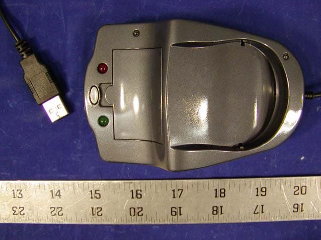
Click to zoom
Application Details
- Equipment Class
- DXX - Part 15 Low Power Communication Device Transmitter
- Date of Grant
- Sep 04, 2002
- Application Purpose
- Original Equipment
- Date of Application
- Sep 04, 2002
- Equipment Note
- Cordless Mouse
- Frequency Range
- 27.04500000 - 27.04500000
- Country
- China
Documents & Files
Document Text
Text extracted from the exhibit documents filed with the FCC. Open a document above to read the original.
Users Manual
HK5001 RF Wireless Optical Mouse – USB+PS2 User’s Guide 1. Insert the batteries into the mouse. Ensure that the batteries are installed correctly and that the (+) & (-) are correct. 2. Turn OFF the Computer. 3. Plug in your USB receiver into the USB port and restart the computer. 4. Once the computer is restarted, press the ID switch on the bottom of the mouse. 5. Press the ID switch on the receiver for 3 seconds. Important: When doing ID setting users need to follow the instruction below: a. Users need to touch “metal sensor” on either sides of the mouse. b. Distance between mouse and receiver cannot be more than 0.5 meter. c. Users need to press both ID switch within 5 second in order to complete ID setting. d. When changing batteries, users need to repeat Step 4 & 5. 6. You should see a red light flashing when the mouse is moved. It means that the mouse and the receiver are communicating successfully. 7. If you don’t see a red light flashing or if the mouse is not responding, you may need to remove the previous mouse driver(s) and restart the computer, and repeat Step 4 & 5. 8. Once Windows is restarted, it will find new hardware and install the correct driver you need to make your mouse function properly. 9. If the scrolling is not working but the mouse is, you may need to go to the add/remove programs in your control panel and remove any previous mouse software that may be installed on your computer and restart the computer again. 10. Under ordinary operation, users need to touch “metal sensor” on the either sides of the mouse. If the user does not touch the sensor, the mouse will be in standby condition. It will reduce the battery energy usage. 11. The receiver performs a battery charger. Users can put a pair of rechargeable battery in the receiver or put the mouse on the receiver for battery charge. Under normal condition, it takes about 15 hours for batteries fully charged.
External Photos
APPENDIX C - EUT EXTERNAL PHOTOGRAPHS Transmitter Chassis - Top View Transmitter Chassis - Bottom View Receiver Chassis - Top View Receiver Chassis - Bottom View
ID Label/Location Info
APPENDIX A - FCC PRODUCT LABELING AND WARNING STATEMENT FCC ID Label Specifications: Text is black in color and is left justified. Labels are printed in indelible ink on permanent adhesive backing and shall be affixed at a conspicuous location on the EUT. Proposed Label Location on EUT Bottom Side of EUT/FCC ID Label Proposed Location FCC Warning Statement If the EUT is too small, the FCC statement could be presented in the user manual. The following is one sample of the FCC Statement: “ This device complies with part 15 of the FCC Rules. Operation is subject to the following two conditions: (1) This device may not cause harmful interference, and (2) this device must accept any interference received, including interference that may cause undesired operation.” FCC ID: P4XH5001 This device complies with Part 15 of the FCC Rules. Operation is subject to the following two conditions: (1) this device may not cause harmful interference, and (2) this device must accept any interference received, including interference that may cause undesired operation. 2.1875" 1.0"
Internal Photos
APPENDIX C - EUT INTERNAL PHOTOGRAPHS Transmitter Main Board - Component View Transmitter Main Board - Solder View Receiver Main Board - Component View Receiver Main Board - Solder View
Operational Description
Electrical Resolution 800DPI Mouse Working Voltage 1.8-3.5v Receiver Working Voltage 5V Mouse Working Current ≦53MA Mouse Standby Current < 10MA Mouse Sleep Current < 0.4MA Transmition Distance ≧1.2M Battery Type Two AAA 650MA/H 1.2V Rechargeable Batteries Rechargeable Battery Current < 100MA Fully Charge Time 15 Hours Working Frequency 27.045MHZ 27.145MHZ Switch Life 1,000,000 Dimention Mouse: 56*104*36.5 mm Receiver: 76*120*41mm Switch Force 75+/-15g Switch Impendence ≧100MΩ
Schematics
1234 A B C D 4 321 D C B A Title NumberRevisionSize A4 Date:27-Aug-2002Sheet of File:F:\RF Opitcal\¹âμçÎÞÏßÊó.ddbDrawn By: 1 2 3 4 5 6 7 8 9 1011 12 13 14 15 16 17 18 19 20 medium ID power saving SW4 SW5 GND SCLK roll 1 roll 2 SDIOPD right OSC OSC rf-cnt rf-data VDD left U2MA6022 C19 30P C8 0.1U C15 100P C12 18P C13 33P C16 36P C14 24P C2 0.1U C7 2.2U C1 100U Q7 KSP10 Q6 2SC2668 Q5 2sc2668 1 2 3 4 5 6 7 89 10 11 12 13 14 15 16 SCLK XA XB YB YA XY-LED REFA REFBOSC_IN GND GND SDIO PD R_BIN VDD OSC_OUT U1A2051 LED1 BT1 R2 30K X1 18MHZ SW5 SW2 SW1 SW4 SW3 X2 6MHZ X3 13.5215MHZ Q4 2SC9015 R4 10K R8 100K R3 10K R7 1.5K R10 56K R610K R9 560R L4 0.47UH C18 12P R5 2.4K C11 0.1U C21 0.1U C10 0.1U C9 100U Q2 2SC9015 Q3 2SC9014 C4 4.5P D2 IN4148 Vin 3 GND 1 Vout 2 U4RT9261B-50CX L2 100UH D3IN5819 C5 100U C6 0.1U C17 100P C20 0P R11 4.7M HK5001-A DY0015501 1 of 1 Àî²ýÓ R16 10K R12 10K R13 10K R14 10K
Test Report
Note: This test report is specially limited to the above client company and product model only. It may not be duplicated without prior written consent of Bay Area Compliance Laboratory Corporation. This report must not be used by the client to claim product endorsement by NVLAP or any agency of the U.S. Government. FCC ID PER PART 15.227 EMI MEASUREMENT AND TEST REPORT For Dynapoint (Dong Guan) Electronics Co. Ltd Hua Guo Shan Industry Park, Jie Kou. Chang An. Dong Guan Guan Dong, China FCC ID: P4XH5001 September 3, 2002 This Report Concerns: Original Report Equipment Type: Cordless Mouse, ITE Test Engineer: Benjamin Jing Report No.: R0208132 Test Date: August 15, 2002 Reviewed By: Jeff Lee Prepared By: Bay Area Compliance Laboratory Corporation 230 Commercial Street Sunnyvale, CA 94085 Tel: (408) 732-9162 Fax: (408) 732-9164 DynaPoint (Dong Guan) Inc. FCC ID: P4XH5001 Report # R0208132Rpt Page 2 of 12 FCC ID Per 15.227 Report TABLE OF CONTENTS 1 - GENERAL INFORMATION..................................................................................................................................3 1.1 PRODUCT DESCRIPTION FOR EQUIPMENT UNDER TEST (EUT) ..............................................................................3 1.2 OBJECTIVE.............................................................................................................................................................3 1.3 RELATED SUBMITTAL(S)/GRANT(S).......................................................................................................................3 1.4 TEST METHODOLOGY............................................................................................................................................3 1.5 TEST FACILITY.......................................................................................................................................................3 1.6 TEST EQUIPMENT LIST...........................................................................................................................................4 1.7 HOST SYSTEM CONFIGURATION.............................................................................................................................4 1.8 LOCAL SUPPORT EQUIPMENT LIST AND DETAILS...................................................................................................5 1.9 EXTERNAL I/O CABLES LIST AND DETAILS...........................................................................................................5 2 - SYSTEM TEST CONFIGURATION.....................................................................................................................6 2.1 JUSTIFICATION.......................................................................................................................................................6 2.2 EUT EXERCISE SOFTWARE....................................................................................................................................6 2.3 SPECIAL ACCESSORIES...........................................................................................................................................6 2.4 SCHEMATICS AND BLOCK DIAGRAM......................................................................................................................6 2.5 EQUIPMENT MODIFICATIONS.................................................................................................................................6 2.6 TEST SETUP CONFIGURATION................................................................................................................................7 2.7 TEST SETUP BLOCK DIAGRAM...............................................................................................................................7 3 - SUMMARY OF TEST RESULTS..........................................................................................................................8 4 - CONDUCTED EMISSIONS ...................................................................................................................................9 4.1 MEASUREMENT UNCERTAINTY..............................................................................................................................9 4.2 EUT SETUP............................................................................................................................................................9 4.3 SPECTRUM ANALYZER SETUP................................................................................................................................9 4.4 TEST PROCEDURE..................................................................................................................................................9 4.5 SUMMARY OF TEST RESULTS...............................................................................................................................10 4.6 CONDUCTED EMISSIONS TEST DATA...................................................................................................................10 4.7 PLOT OF CONDUCTED EMISSIONS TEST DATA.....................................................................................................10 5 - RADIATED EMISSIONS TEST ..........................................................................................................................11 5.1 MEASUREMENT UNCERTAINTY............................................................................................................................11 5.2 EUT SETUP..........................................................................................................................................................11 5.3 SPECTRUM ANALYZER SETUP..............................................................................................................................11 5.4 TEST PROCEDURE................................................................................................................................................11 5.5 C…
Text truncated - open the document above for the full version.
Test Setup Photos
APPENDIX B - TEST SETUP PHOTOGRAPHS Conducted Emission Radiated Emission
Contact Information
Applicant
Robert Su(General Manager)
Test Firm
Bay Area Compliance LaboratoryJohn Chan
Technical Specifications
| # | Rule Parts | Frequency Range | Power Output |
|---|---|---|---|
| 1 | 15C | 27.045 MHz - 27.045 MHz | - |
Other Applications from Dyna Point (Dong Guan) Electronic
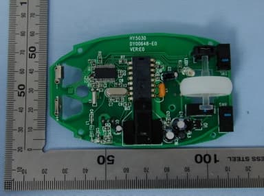
P4XH1300M
Dec 09, 2004Wireless Mouse
Equipment Class
DXX - Part 15 Low Power Communication Device Transmitter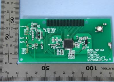
P4XH1300K
Dec 09, 2004WIRELESS KEYBOARD
Equipment Class
DXX - Part 15 Low Power Communication Device Transmitter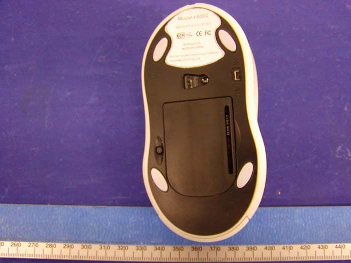
P4XHZ5000
Aug 15, 2004RF optical mouse transmitter
Equipment Class
DXX - Part 15 Low Power Communication Device Transmitter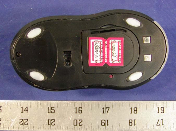
P4XHL5001
Sep 14, 2003Cordless Mouse
Equipment Class
DXX - Part 15 Low Power Communication Device Transmitter
P4XKB998
Sep 14, 2003Cordless Keyboard
Equipment Class
DXX - Part 15 Low Power Communication Device Transmitter