P5EESC1702Residential Gateway
Elesign INC.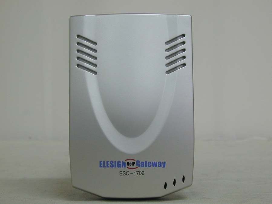
Click to zoom
Application Details
- Equipment Class
- JBP - Part 15 Class B Computing Device Peripheral
- Date of Grant
- Apr 09, 2002
- Application Purpose
- Original Equipment
- Date of Application
- Apr 09, 2002
- Equipment Note
- Residential Gateway
- Company
- Elesign INC.
- Country
- South Korea
Documents & Files
Document Text
Text extracted from the exhibit documents filed with the FCC. Open a document above to read the original.
Users Manual
ESC1702 Manual ELESIGN VoIP Gateway 1 ELESIGN VoIP GATEWAY User Manual COMPLIANCES ESC1702 Manual ELESIGN VoIP Gateway 2 FCC Class B Certification 1. This device complies with Part 15 of the FCC Rules. Operation is subject to the following conditions: This device may not cause harmful interference. 2. This device must accept any interference received, including interference that may cause undesired operation. Warning! This equipment has been tested and found to comply with the limits for a Class B digital device, pursuant to Part 15 of the FCC Rules. These limits are designed to provide reasonable protection against harmful interference in a residential installation. This equipment generates, uses and can radiate radio frequency energy and, if not installed and used in accordance with the instructions, may cause harmful interference to radio communications. However, there is no guarantee that interference will not occur in a particular installation. If this equipment does cause harmful interference to radio or television reception, which can be determined by turning the equipment off and on, the user is encouraged to try to correct the interference by one or more of the following measures: z Reorient or relocate the receiving antenna. z Increase the distance between the equipment and receiver. z Connect the equipment into an outlet on a circuit different from the one to which the receiver is connected. z Consult the dealer or an experienced radio / TV technician for help. About This Manual This Manual provides basic information on how to install and connect Elesign IP ESC1702 Manual ELESIGN VoIP Gateway 3 Phone to the network. It also includes features and functions of Elesign IP phone components, and how to use them. Before Getting Started Before you can connect ELESIGN GATEWAY to the network and use it, you must have a high-speed Internet connection installed. A high-speed connection includes such environments as ADSL, cable modem, and a leased line. Precaution Elesign Inc. has copyright to this manual. Any part of this manual cannot be reproduced or transferred electronically, mechanically, or acoustically without permission of Elesign Inc. The material of this manual could be changed for the purpose of the product enhancement. Copyright Elesign Inc. All rights reserved Contents Getting started with Elesign Gateway 1. Elesign Gateway ESC1702 Manual ELESIGN VoIP Gateway 4 2. Installation of Elesign Gateway 3. Check Installation by LED PC Network Setup 1. ADSL, Cable Modem, Leased –Dynamic IP Users 2. Leased – Static IP Users WIN98/WINme Users WIN2000 Users Elesign Gateway Network Set Up Elesign Gateway H.323 Set Up Make a Call using Elesign Gateway Software Upgrade Troubleshooting Getting started with Elesign Gateway ESC1702 Manual ELESIGN VoIP Gateway 5 1. Elesign Gateway Elesign gateway is a 1-port gateway, which enables Internet phone call thru existing conventional phone. It’s a stand-alone device, which means no PC connection is necessary to use Elesign Gateway except for the initial configuration thru built-in web-server. Components check list 9 1 Elesign Gateway 9 1 LAN Cable 9 1 Telephone line cord 9 1 Elesign Gateway User Manual 9 1 Adaptor 2. Installation PC is not necessary to use Elesign gateway except for setup. ESC1702 Manual ELESIGN VoIP Gateway 6 Normal Phone PC PSTN Internet ADSL M odem Csble M odem LAN H UB Remove the phone line, which is connected from the wall jack to your existing analogue phone, and connect it to ‘PSTN’ port. Find a phone line in the box and connect between ‘PHONE’ port and your existing analogue phone Remove from your PC the LAN cable for Internet connection and connect it to ‘UP’ port. Find a LAN cable in the box and connect between ‘PC’ port and your PC. Connect an adapter in the box to ‘POWER’. 3. Check Installation by LED ESC1702 Manual ELESIGN VoIP Gateway 7 When Internet line (LAN cable) is connected to ELESIGN GATEWAY, the color of ‘Link’ is ‘Green’. And when Computer is connected and power of PC is turned on, the color changed to ‘Orange’. If only PC is connected, color of ‘Link’ is ‘RED’. When you pick up the handset of the telephone, the color of ‘Hook’ is ‘Red’. When adapter is connected to ELESIGN GATEWAY, initial LED color of ‘Phone’ is orange and turns to green with ‘click’ sound. PC Network Set Up User should set up network PC to use the gateway. Please choose appropriate network environment you are using and follow the direction for PC network set up. ESC1702 Manual ELESIGN VoIP Gateway 8 1. ADSL, Cable modem, Leased Line – Dynamic IP users After the installation, please restart the computer. If computer is turned off, simply turn on the computer after the installation. 2. For Leased Line-Static IP Users For WIN98/ Window Me users Click on ‘Start’ button ‘Select ‘Control Panel’ from ‘setting’ of start menu. Select ‘Network’ from control panel ESC1702 Manual ELESIGN VoIP Gateway 9 Select TCP/IP and click on ‘Property’ button Select ‘Obtain an IP address automatically’ and click on ‘OK’ button ESC1702 Manual ELESIGN VoIP Gateway 10 Popup window will appear to restart the computer, then restart the computer right away by clicking on ‘OK’ button ESC1702 Manual ELESIGN VoIP Gateway 11 Win2000 Users Click on ‘Start’ button Select ‘Control Panel’ from ‘Setting’ of start menu. Select ‘Network’. Select ‘Local Connection’ Click on ‘Properties’ button Select ‘TCP/IP’ and click on ‘Property’ button. Select ‘Obtain an IP address automatically’ and click on ‘OK’ button. Click on ‘OK’ to close window. Note: If you are leased line – static IP user, please write down the network information such as IP address, gateway, subnet mask, DNS, etc. before you select ‘Obtain IP address automatically’. Those are necessary to do Gateway Network Setup. Elesign Gateway Network Set Up ESC1702 Manual ELESIGN VoIP Gateway 12 User should set up for network to use access gateway thru Internet according to…
Text truncated - open the document above for the full version.
External Photos
EUT Front View EUT Side View
Test Report
Report Number : ESTF150202-001 , Web : www. estech. co. kr Page 1 of 16 Compliance Test Report for FCC Report Number ESTF150202-001 Company Name Elesign INC. Address 403, KOLON techno valley, 60-4, Kasan-dong, Kumcheon gu, Seoul, Korea Applicant Telephone 82-2-866-6190 Product Name Residential Gateway Model No. ESC 1702 Manufacturer Elesign INC. Product Serial No. - Country of origin Korea Test data Date of Receipt 2002.1.30 Date of Issue 2002.2.14 Testing Location ESTECH. Co., Ltd 97-1, Hoi-uk Ri Ma-jang Myon, Icheon city, Kyung-Ki Do, Korea Standard FCC PART 15 2001 , ANSI C 63.4 2001 Conducted Emission Class A Class B Test Result : OK Emission Test Radiated Emission Class A Class B Test Result : OK Measurement Facility Registration Number : 94696 Tested by : Senior Engineer J. M. Yang (Signature/Seal) Reviewed by : Director T. K. Lee (Signature/Seal) Abbreviation OK, Pass = Passed, Fail = Failed, N/A = not applicable * Note - This test report is not permitted to copy partly without our permission - This test result is dependent on only equipment to be used - This test result based on a single evaluation of one sample of the above mentioned Report Number : ESTF150202-001 , Web : www. estech. co. kr Page 2 of 16 Contents 1. Laboratory Information . .................................................................................... 3 2. Description of EUT. ...............................................................................................4 3. Test Standards. ....................................................................................................... 7 4. Measurement condition. ....................................................................................... 8 5. Measurement of radiated emission. ....................................................................9 5.1 Measurement equipment. ..............................................................................9 5.2 Environmental conditions. ............................................................................. 9 5.3 Test data. . ........................................................................................................10 6. Measurement of conducted emission. ............................................................... 11 6.1 Measurement equipment. ............................................................................ 11 6.2 Environmental conditions. ...........................................................................11 6.3 Test data. . .......................................................................................................12 6.4 Spectral Diagram. . .................................................................................. 13,14 7. Test Setup Photographs. .............................................................................. 15,16 Report Number : ESTF150202-001 , Web : www. estech. co. kr Page 3 of 16 1. Laboratory Information 1.1 General This EUT (Equipment Under Test) has been shown to be capable of compliance with the applicable technical standards and tested in accordance with the measurement procedures as indicated in this report ESTECH Lab. attests to accuracy of test data. All measurement reported herein were performed by ESTECH Co., Ltd. ESTECH Lab. assume full responsibility for the completeness of these measurements and vouch for the qualifications of all persons taking them. 1.2 Test Lab. Corporation Name : ESTECH Co. Ltd . Head Office : 3 rd Fl., Chungdam Bldg., 119-1, Chungdam-dong Kangnam-gu , Seoul, Korea (Safety & Telecom. Test Lab ) EMC Test Lab . : 58-1, O-San Ri, Ga-Nam Myon, Yeo-Joo Gun, Kyung-Ki Do, Korea 97-1, Hoi-uk Ri Ma-jang Myon, Icheon city, Kyung-Ki Do, Korea Branch Office : USA-ESTECH INC. 21801 Stevens Creek Blvd. Suite 2A Cupertino, CA95014 1.3 Official Qualification(s) MIC : Granted Accreditation from Ministry of Information & Communication for EMC, Safety and Telecom. KOLAS : Accredited Lab. By Korea Laboratory Accreditation Schema base on CENELEC requirements FCC : Filed Laboratory at Federal Communications Commission VCCI : Granted Accreditation from Voluntary Control Council for Interference from ITE Report Number : ESTF150202-001 , Web : www. estech. co. kr Page 4 of 16 2. Description of EUT 2.1 Summary of Equipment Under Test ♦ EUT Name : Residential Gateway ♦ Model Number : ESC 1702 ♦ Serial Number : - ♦ Manufacturer : Elesign INC. ♦ Country of origin : KOREA ♦ Power Rating Adaptor Using . Input : AC 90~260V , 60 Hz Output : DC 5V/1.0A ♦ Test Date Test Date : 2002. 2. 4 2.2 General descriptions of EUT - ESC 1702 is a 1-port gateway, which enables Internet phone call thru existing conventional phone. It’s a stand-alone device, which means no PC connection is necessary to use ESC 1702 except for the initial configuration thru built-in web-server. Report Number : ESTF150202-001 , Web : www. estech. co. kr Page 5 of 16 2.3 Circuit Diagram Attached file : 12 file 2.4 EUT Block Diagram Report Number : ESTF150202-001 , Web : www. estech. co. kr Page 6 of 16 2.5 EUT Figure Report Number : ESTF150202-001 , Web : www. estech. co. kr Page 7 of 16 3. Test Standards Test Standard : FCC PART 15 (2001) This Parts sets out the regulations under which an intentional, unintentional, or incidental radiator may be operated without an individual license. It also contains the technical specifications, administrative requirements and other conditions relating to the marketing of Part 15 devices. Test Method : ANSI C 63.4 (2001) This standard sets forth uniform methods of measurement of radio-frequency (RF) signals and noise emitted from both unintentional and intentional emitters of RF energy in the frequency range 9 kHz to 40 GHz. Methods for the measurement of radiated and AC power-line conducted radio noise are covered and may be applied to any such equipment unless otherwise specified by individual equipment requirements. These methods cover measurement of certain decides that deliberately radiate energy…
Text truncated - open the document above for the full version.
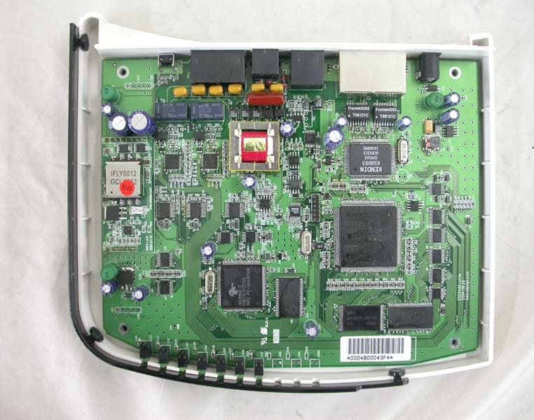
Test Setup Photos
Report Number : ESTF150202-001 , Web : www. estech. co. kr Page 16 of 17 7 Test Setup Photographs 7.1 Setup for Radiated Test : 30 ~ 1000 MHz [ Front ] [ Rear ] Report Number : ESTF150202-001 , Web : www. estech. co. kr Page 17 of 17 7.2 Setup for Conducted Test : 0.45 ~ 30 MHz [ Front ] [ Rear ]
Contact Information
Applicant
Lee Eun Gu(Associate Research Engineer)
[email protected]82-2-6332-6190
Test Firm
Bay Area Compliance LaboratoryJohn Chan
Technical Specifications
| # | Rule Parts | Frequency Range | Power Output |
|---|---|---|---|
| 1 | 15B | - | - |
Other Applications from Elesign INC.
P5EESC2420
Apr 13, 20052-Port VoIP Gateway
Equipment Class
JBP - Part 15 Class B Computing Device Peripheral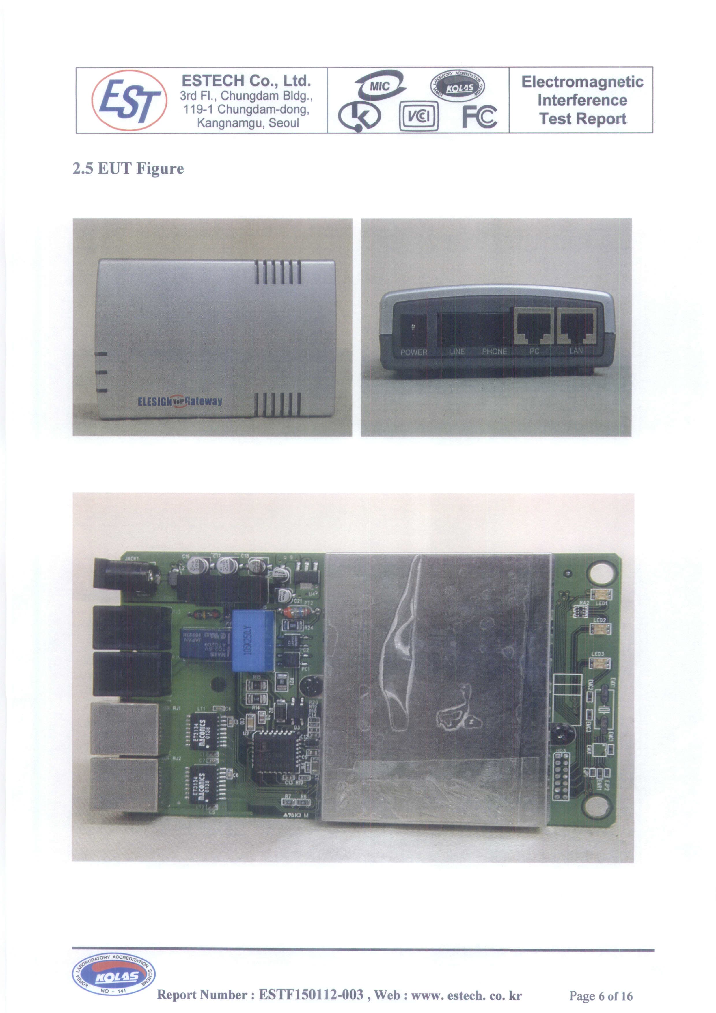
P5EESC1700
Dec 30, 2001Residential Gateway
Equipment Class
JBP - Part 15 Class B Computing Device Peripheral