P5EESC24202-Port VoIP Gateway
Elesign INC.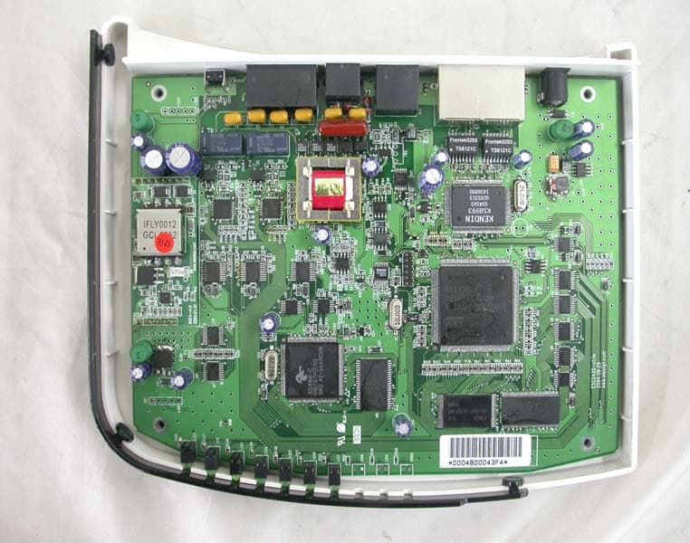
Click to zoom
Application Details
- Equipment Class
- JBP - Part 15 Class B Computing Device Peripheral
- Date of Grant
- Apr 13, 2005
- Application Purpose
- Original Equipment
- Date of Application
- Apr 13, 2005
- Equipment Note
- 2-Port VoIP Gateway
- Company
- Elesign INC.
- Country
- South Korea
Documents & Files
Document Text
Text extracted from the exhibit documents filed with the FCC. Open a document above to read the original.
Users Manual
ELESIGN VoIP GATEWAY ESC2420(H.323 Version) User Guide CAUTION: Changes or modifications not expressly approved by the manufacturer responsible for compliance could void the user’s authority to operate the equipment WA R N I N G This device complies with part 15 of the FCC Rules. Operation is subject to the following two conditions: (1) This device may not cause harmful interference, and (2) this device must accept any interference received, including interference that may cause undesired operation. INFORMATION TO USER: This equipment has been tested and found to comply with the limit of a Class B digital device, pursuant to Part 15 of the FCC Rules. These limits are designed to provide reasonable protection against harmful interference in a residential installation. This equipment generates, uses and can radiate radio frequency energy and, if not installed and used in accordance with the instructions, may cause harmful interference to radio communications. However, there is no guarantee that interference will not occur in a particular installation; if this equipment does cause harmful interference to radio or television reception, which can be determined by turning the equipment off and on, the user is encouraged to try to correct the interference by one or more of the following measures: 1. Reorient / Relocate the receiving antenna. 2. Increase the separation between the equipment and receiver. 3. Connect the equipment into an outlet on a circuit difference from that to which the receiver is connected. 4. Consult the dealer or an experienced radio/TV technician for help ESC2420 User Guide version1.0 1 About This Manual This Manual provides basic information on how to install and connect Elesign Gateway to the network. It also includes features and functions of Elesign Gateway components, and how to use them. Before Getting Started Before you can connect ELESIGN GATEWAY to the network and use it, you must have a high-speed Internet connection installed. A high-speed connection includes such environments as DSL, cable modem, and a leased line. Precaution Elesign Inc. has copyright to this manual. Any part of this manual cannot be reproduced or transferred electronically, mechanically, or acoustically without permission of Elesign Inc. The material of this manual could be changed for the purpose of the product enhancement. Copyright Elesign Inc. All rights reserved ESC2420 User Guide version1.0 2 Contents Chapter 1 Summary and Introduction..........................................................4 I. Summary..............................................................................5 II. Introduction...........................................................................6 Chapter 2 Installation..................................................................................7 I. Installation and Procedure at a glance............................................8 II. Status Checkup using LED........................................................11 Chapter 3 PC Network Setup.....................................................................12 I. Before Getting Started..............................................................13 II. PC Network Setup...................................................................14 Chapter 4 Gateway Network Setup...........................................................18 I. Before Getting Started.............................................................19 II. Connect to Setup Page..............................................................20 III. Gateway Network Setup............................................................21 Chapter 5 VoIP Setup ................................................................................23 I. Before Getting Started............................................................24 II. VoIP Setup.............................................................................25 III. Make a Call..........................................................................29 Chapter 6 Advanced Setup........................................................................30 I. Console Setup........................................................................32 II. Volume Setup............................................................................34 III. DHCP Setup............................................................................35 IV. Use NAT Function ..................................................................37 V. Phonebook Setup....................................................................39 VI. Firmware Upgrade ................................................................42 ESC2420 User Guide version1.0 3 Chapter 7 Other VoIP Setup Option............................................................43 I. Using Media Gateway...............................................................44 II. Direct Call..............................................................................45 Chapter 8 Appendix...................................................................................46 I. How to check MAC Address ....................................................47 II. Configuration and Installation with other equipments ....................48 ESC2420 User Guide version1.0 4 Chapter 1 Summary and Introduction I. Summary.......................................................................................5 II. Introduction..................................................................................6 1. Contents Checklist..........................................................................6 2. Specifications................................................................................6 ESC2420 User Guide version1.0 5 I. Summary ESC2420 is a 2-port VoIP gateway and it connects standard telephones and fax machines to IP-based networks. It provides two FXS interfaces and one FXO interface that will enable more calls to be routed through the gateway with or without using dir…
Text truncated - open the document above for the full version.
External Photos
1. FRONT 2. REAR 3. INTERNAL
ID Label/Location Info
Elesign Inc. Residential Gateway MODEL : ESC-2420 FCC ID : P5EESC2420 This device complies with part 15 of the FCC Rules. Operation i s subject to the following two conditions: (1) This device may no t cause harmful interference, and (2) this device must accept any interference received, including interference that may cause undesired operation.
Internal Photos
INTERNAL PHOTO 1. MAIN 1.1 Front 1.2 Rear
Operational Description
Elesign Inc. FCC ID P5EESC2420 -Operational description- ESC2420 is a 2-port VoIP gateway and it connects standard telephones and fax machines to IP-based networks. It provides two FXS interfaces and one FXO interface that will enable more calls to be routed through the gateway with or without using directly connected telephones to the gateway. The gateway can be used with Internet connection such as ADSL modem, Cable Modem, and leased Line. The gateway has NAT function, which allows connecting several PCs to use the Internet simultaneously. The basic Internet calls with this gateway are service thru VoIP service provider. With PSTN back up allows to receive a call thru PSTN and automatically switches to PSTN when power-out or problem in networking occurs.
Test Report
Compliance Test Report for FCC Company name Address Telephone Product name Model No. Serial No. Test date Testing location Standard □ Class A ■ Class B Test resultOK □ Class A ■ Class B Test resultOK Tested by Reviewed by Abbreviation * Note - This test report is not permitted to copy partly without our permission - This test result is dependent on only equipment to be used - This test result based on a single evaluation of one sample of the above mentioned Report Number : ESTF150504-004 , Web : www. estech. co. kr Page 1 of 14 Report NumberESTF150504-004 Manufacturer Country of origin Applicant Product 2005-04-14 Residential Gateway ESC-2420 0004B00043F4 Elesign Inc. KOREA Date of issue ESTECH. Co., Ltd. 97-1 Hoiuk-Ri Majang-Myon, Icheon-city, KyungKi-Do, Korea Test item ■ Conducted Emission ■ Radiated Emission FCC PART 15 2002 , ANSI C 63.4 2001 2005-03-21 ~2005-04-14 OK, Pass = Passed, Fail = Failed, N/A = not applicable Elesign Inc. #403, KOLON Techno-valley, 60-4, Kasan-dong, Kumcheon-gu, Seoul, 153-801, R.O.Korea 82-2-866-6190 Measurement facility registration number Senior Engineer J.M. Yang Director T.K. Lee 94696 (Signature) (Signature) 3 4 5 6 8 8 8 9 10 10 10 11 12 14 Appendix 1. Spectral diagram Appendix 2. Phorographs of EUT in side PCB Appendix 3. Block diagram of EUT Appendix 4. Circuit Diagram Report Number : ESTF150504-004 , Web : www. estech. co. kr Page 2 of 14 5. Measurement of radiated emission ............................................................... 5.1 Measurement e quipment ........................................................................... Contents 1. Laboratory Information ................................................................................. 2. Description of EUT ....................................................................................... 3. Test Standards ............................................................................................. 4. Measurement condition ................................................................................. 5.2 Environmental conditions ........................................................................ 5.3 Test data ............................................................................................. ... 7. Photographs of test setup ........................................................................... 8. Photogra phs of EUT .................................................................................... 6. Measurement of conducted emission ............................................................ 6.1 Measurement e quipment ........................................................................... 6.2 Environmental conditions ........................................................................... 6.3 Test data ................................................................................................ 1. Laboratory Information 1.1 General 1.2 Test Lab. Corporation Name : ESTECH Co. Ltd Head Office : Rm 1015, World Venture Center II, 426-5, Gasan-dong, Geumcheon-gu, Seoul, Kor e (Safety & Telecom. Test Lab) EMC Test Lab : 58-1 Osan-Ri, GaNam-Myon, YeoJoo-Gun, KyungKi-Do, Korea 97-1 Hoiuk-Ri Majang-Myon, Icheon-city, KyungKi-Do, Korea 1.3 Official Qualification(s) MIC : Granted Accreditation from Ministry of Information & Communication for EMC, Safety and Telecommunication KOLAS : Accredited Lab By Korea Laboratory Accreditation Schema base on CENELEC requirements FCC : Filed Laboratory at Federal Communications Commission VCCI : Granted Accreditation from Voluntary Control Council for Interference from ITE This EUT (Equipment Under Test) has been shown to be capable of compliance with the applicable technical standards and is tested in accordance with the measurement procedures as indicated in this report. ESTECH Lab attests to accuracy of test data. All measurement reported herein were performed by ESTECH Co., Ltd. ESTECH Lab assume full responsibility for the completeness of these measurements and vouch for the qualifications of all persons taking them. Report Number : ESTF150504-004 , Web : www. estech. co. kr Page 3 of 14 2. Description of EUT 2.1 Summary of Equipment Under Test NONE: Model Number : ESC-2420 Serial Number : Manufacturer : Country of origin : Rating : Receipt Date : 2.2 General descriptions of EUT Using Freq. :25MHz/10MHz/12.288MHz Report Number : ESTF150504-004 , Web : www. estech. co. kr Page 4 of 14 Residential Gateway 0004B00043F4 Elesign Inc. KOREA INPUT:AC120V / 60Hz 2005-03-21 3. Test Standards Test Standard : FCC PART 15 (2002) Test Method : ANSI C 63.4 (2001) This standard sets forth uniform methods of measurement of radio-frequency (RF) signals and noise emitted from both unintentional and intentional emitters of RF energy in the frequency range 9 kHz to 40 GHz. Methods for the measurement of radiated and AC power-line conducted radio noise are covered and may be applied to any such equipment unless otherwise specified by individual equipment requirements. These methods cover measurement of certain decides that deliberately radiate energy, such as intentional emitters, but does not cover licensed transmitters. This standard is not intended for certification/approval of avionic equipment or for industrial, scientific, and medical (ISM) equipment These method apply to the measurement of individual units or systems comprised of multiple units This Standard sets out the regulations under which an intentional, unintentional, or incidental radiator may be operated without an individual license. It also contains the technical specifications, administrative requirements and other conditions relating to the marketing of Part 15 devices. Report Number : ESTF150504-004 , Web : www. estech. co. kr Page 5 of 14 4. Measurement Condition 4.1 EUT Operation. 4.2 Configuration and Peripherals * The EUT was in the following operation mode during all testing * The operational conditions of the EUT was determined by the manufacturer acco…
Text truncated - open the document above for the full version.
Test Setup Photos
TEST SETUP PHOTO 1. Conducted Emission setup photo 1.1. Front 1.2. Rear 2. Radiated Emission setup photo 2.1 Front 2.2. Rear
Contact Information
Applicant
Lee Eun Gu(Associate Research Engineer)
[email protected]82-2-6332-6190
Technical Contact
ES TechJin-Mo Yang
[email protected]82-54-470-4537
97-1 Hoiuk-Ri Majang-Myon · Icheon City, KyngKi-Do · South Korea
Test Firm
Estech Co., Ltd.Ike Chung
Technical Specifications
| # | Rule Parts | Frequency Range | Power Output |
|---|---|---|---|
| 1 | 15B | - | - |
Other Applications from Elesign INC.
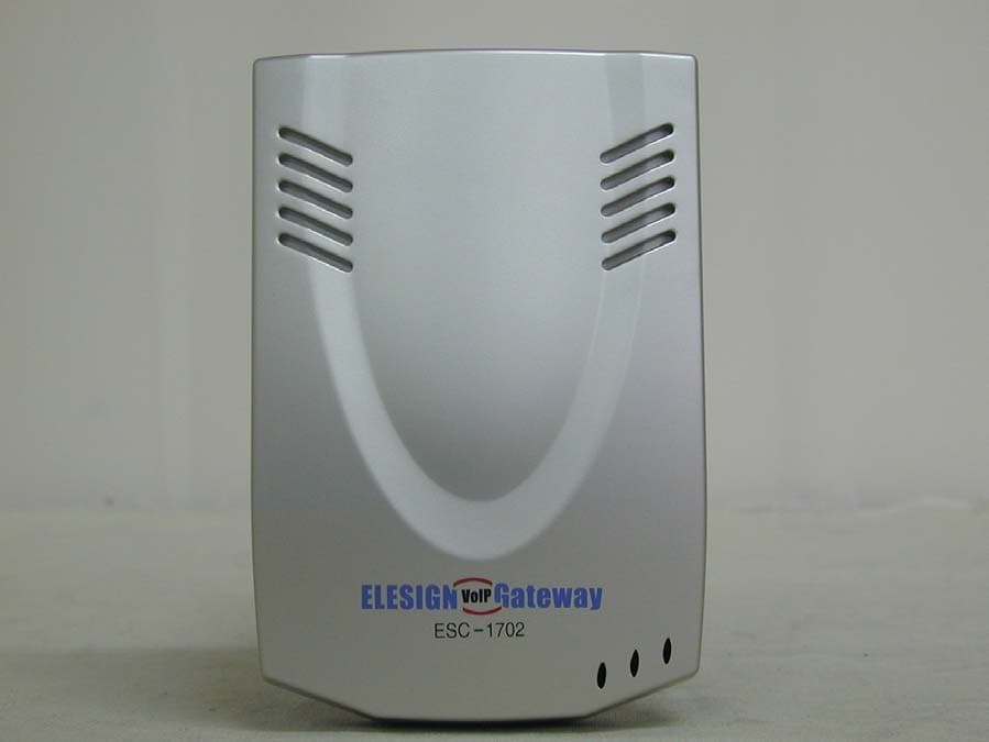
P5EESC1702
Apr 09, 2002Residential Gateway
Equipment Class
JBP - Part 15 Class B Computing Device Peripheral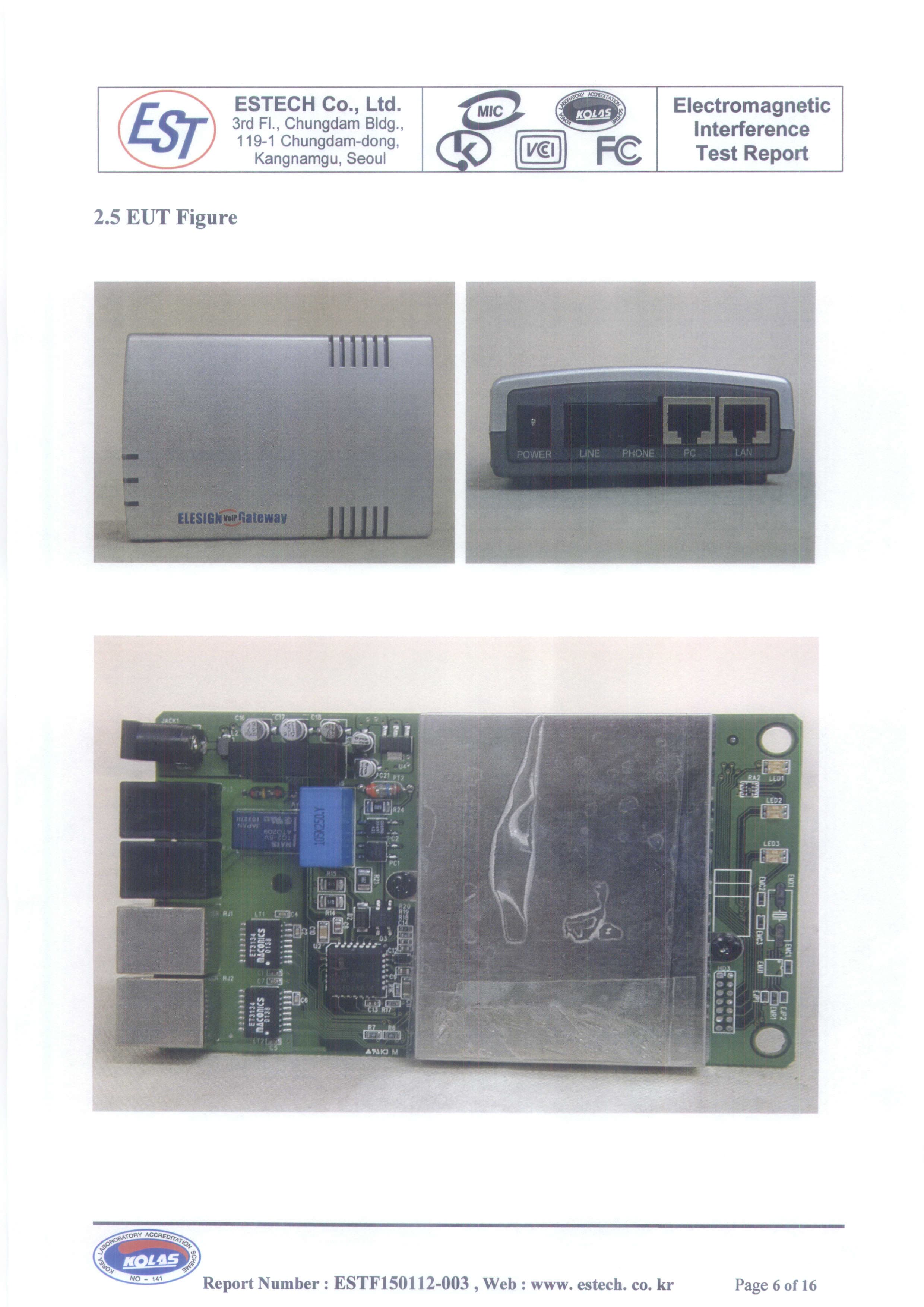
P5EESC1700
Dec 30, 2001Residential Gateway
Equipment Class
JBP - Part 15 Class B Computing Device Peripheral