P5IMBS2LPEMobile base station with L-Band Sat, GSM and WLAN
Wireless Matrix Corporation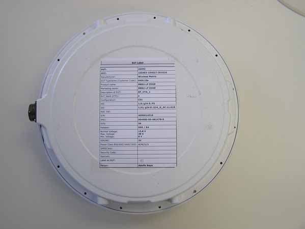
Click to zoom
Application Details
- Equipment Class
- TNB - Licensed Non-Broadcast Station Transmitter
- Date of Grant
- Dec 10, 2006
- Application Purpose
- Original Equipment
- Date of Application
- Dec 10, 2006
- Equipment Note
- Mobile base station with L-Band Sat, GSM and WLAN
- Frequency Range
- 1626.50000000 - 1660.50000000
- Company
- Wireless Matrix Corporation
- Country
- United States
Documents & Files
Document Text
Text extracted from the exhibit documents filed with the FCC. Open a document above to read the original.
Users Manual
Wireless Matrix Corporation Document MBUD-0122v1 12369-B Sunrise Valley Drive, Reston, VA 20191 Version 1.0 Phone : (703) 262-0500 October 17, 2006 FAX : (703) 262-0380 www.wirelessmatrixcorp.com Wireless Matrix MBS2-LP EDGE User Guide MBS-LP EDGE User Guide Document MBUD-0122v1.0 Wireless Matrix Proprietary and Confidential 2/16 MBS2-LP EDGE User Guide Copyright © 2006 Wireless Matrix USA, Inc. All rights reserved. Printed in the United States of America This document is proprietary to Wireless Matrix USA, Inc. Do not reproduce, use or disclose without permission. We have made every effort to ensure the accuracy of all information contained in this document. However, Wireless Matrix USA, Inc. makes no expressed or implied warranty or representation based upon the enclosed information. Revision History: Version 1.0 10/17/06 Initial Draft MBS-LP EDGE User Guide Document MBUD-0122v1.0 Wireless Matrix Proprietary and Confidential 3/16 MBS2-LP EDGE User Guide TABLE OF CONTENTS INTRODUCTION............................................................................................................. 4 TECHNICAL SUPPORT.................................................................................................................................. 4 REGULATORY STATEMENTS........................................................................................................................ 4 OTHER SAFETY PRECAUTIONS.................................................................................................................... 5 GENERAL DESCRIPTION ............................................................................................ 6 MBS2-LP UNIT........................................................................................................................................... 6 WAW NETWORK........................................................................................................................................ 6 COMPONENTS ................................................................................................................ 8 COMMAND SERVER..................................................................................................................................... 8 SATELLITE MODEM..................................................................................................................................... 8 GPRS/EDGE MODEM................................................................................................................................. 8 802.11B MODEM......................................................................................................................................... 8 GPS RECEIVER............................................................................................................................................ 9 KEYFOB RECEIVER...................................................................................................................................... 9 FEATURES ..................................................................................................................... 10 MULTI-NETWORK ROUTING (MNR) ......................................................................................................... 10 BANDWIDTH STEERING (BWS) ................................................................................................................. 10 ACTIVE NETWORK (AN) DETERMINATION................................................................................................ 11 MAGIC PACKET......................................................................................................................................... 11 IN-YARD ACCESS...................................................................................................................................... 11 WIRELESS DHCP (WDHCP) .................................................................................................................... 12 INTERNET PROTOCOLS SUPPORT............................................................................................................... 12 ALERT AND PERSONAL ALERT.................................................................................................................. 13 MISCELLANEOUS ....................................................................................................... 14 ADDRESSING............................................................................................................................................. 14 THROUGHPUT............................................................................................................................................ 14 TOOLS....................................................................................................................................................... 14 INSTALLATION OVERVIEW .................................................................................... 16 INSTALLATION.......................................................................................................................................... 16 MBS2-LP OPERATION.............................................................................................................................. 16 EQUIPMENT FAILURE OR DAMAGE............................................................................................................ 16 MBS-LP EDGE User Guide Document MBUD-0122v1.0 Wireless Matrix Proprietary and Confidential 4/16 MBS2-LP EDGE User Guide INTRODUCTION This guide explains procedures for using the Wireless Matrix Mobile Base Station 2 Low Profile (MBS2-LP) modem as installed on a vehicle for data communications. Technical Support Technical questions should be directed to the Customer Care team at (866) 456-7522. Regulatory Statements The following regulatory approvals apply for the Mobile Base Station 2 LP with EDGE(MBS2-LP): • FCC FCCID = P5IMBSLPE • IC ICID = 1478A-MBSLPE • PTCRB The Wireless Mat…
Text truncated - open the document above for the full version.
Users Manual
Wireless Matrix Corporation Document MBUD-0122v1 12369-B Sunrise Valley Drive, Reston, VA 20191 Version 1.0 Phone : (703) 262-0500 October 17, 2006 FAX : (703) 262-0380 www.wirelessmatrixcorp.com Wireless Matrix MBS2-LP EDGE User Guide MBS-LP EDGE User Guide Document MBUD-0122v1.0 Wireless Matrix Proprietary and Confidential 2/16 MBS2-LP EDGE User Guide Copyright © 2006 Wireless Matrix USA, Inc. All rights reserved. Printed in the United States of America This document is proprietary to Wireless Matrix USA, Inc. Do not reproduce, use or disclose without permission. We have made every effort to ensure the accuracy of all information contained in this document. However, Wireless Matrix USA, Inc. makes no expressed or implied warranty or representation based upon the enclosed information. Revision History: Version 1.0 10/17/06 Initial Draft MBS-LP EDGE User Guide Document MBUD-0122v1.0 Wireless Matrix Proprietary and Confidential 3/16 MBS2-LP EDGE User Guide TABLE OF CONTENTS INTRODUCTION............................................................................................................. 4 TECHNICAL SUPPORT.................................................................................................................................. 4 REGULATORY STATEMENTS........................................................................................................................ 4 OTHER SAFETY PRECAUTIONS.................................................................................................................... 5 GENERAL DESCRIPTION ............................................................................................ 6 MBS2-LP UNIT........................................................................................................................................... 6 WAW NETWORK........................................................................................................................................ 6 COMPONENTS ................................................................................................................ 8 COMMAND SERVER..................................................................................................................................... 8 SATELLITE MODEM..................................................................................................................................... 8 GPRS/EDGE MODEM................................................................................................................................. 8 802.11B MODEM......................................................................................................................................... 8 GPS RECEIVER............................................................................................................................................ 9 KEYFOB RECEIVER...................................................................................................................................... 9 FEATURES ..................................................................................................................... 10 MULTI-NETWORK ROUTING (MNR) ......................................................................................................... 10 BANDWIDTH STEERING (BWS) ................................................................................................................. 10 ACTIVE NETWORK (AN) DETERMINATION................................................................................................ 11 MAGIC PACKET......................................................................................................................................... 11 IN-YARD ACCESS...................................................................................................................................... 11 WIRELESS DHCP (WDHCP) .................................................................................................................... 12 INTERNET PROTOCOLS SUPPORT............................................................................................................... 12 ALERT AND PERSONAL ALERT.................................................................................................................. 13 MISCELLANEOUS ....................................................................................................... 14 ADDRESSING............................................................................................................................................. 14 THROUGHPUT............................................................................................................................................ 14 TOOLS....................................................................................................................................................... 14 INSTALLATION OVERVIEW .................................................................................... 16 INSTALLATION.......................................................................................................................................... 16 MBS2-LP OPERATION.............................................................................................................................. 16 EQUIPMENT FAILURE OR DAMAGE............................................................................................................ 16 MBS-LP EDGE User Guide Document MBUD-0122v1.0 Wireless Matrix Proprietary and Confidential 4/16 MBS2-LP EDGE User Guide INTRODUCTION This guide explains procedures for using the Wireless Matrix Mobile Base Station 2 Low Profile (MBS2-LP) modem as installed on a vehicle for data communications. Technical Support Technical questions should be directed to the Customer Care team at (866) 456-7522. Regulatory Statements The following regulatory approvals apply for the Mobile Base Station 2 LP with EDGE(MBS2-LP): • FCC FCCID = P5IMBSLPE • IC ICID = 1478A-MBSLPE • PTCRB The Wireless Mat…
Text truncated - open the document above for the full version.
Cover Letter(s)
ctc_gn_01_00.doc (General);2/9/07 Page 1 of 1 CETECOM Inc. 411 Dixon Landing Road Milpitas, CA 95035 U.S.A. Phone: + 1 408 586 6200 Fax: + 1 408 586 6299 e-mail: [email protected] URL: www.cetecom.com Statement To Whom it concern Wireless Matrix is aware has been notified that part 25 devices not requiring certification and that EA-certification is voluntary. Wireless Matrix is also aware that before equipment operation additional certification by FCC International Bureau at time of licensing is required. Wireless Matrix has several devices on the market for years operating part 25 radios and is very familiar with all the procedures and requirements. Sincerely, Lothar Schmidt CETECOM Inc.
External Photos
Photos External : FCC ID: P5IMBS2LPE IC-ID: 1478A-MBS2LPE Page 1 of 2 MBS2-LP EDGE FRONT VIEW Photos External : FCC ID: P5IMBS2LPE IC-ID: 1478A-MBS2LPE Page 2 of 2 MBS2-LP EDGE BOTTOM VIEW
ID Label/Location Info
LABEL LOCATION ON DEVICEFCC-ID: P5IMBS2LPE IC-ID: 1478A-MBS2LPE
Internal Photos
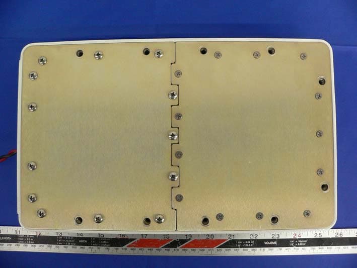
Photos Internal : FCC ID: P5IMBS2LPE IC-ID: 1478A-MBS2LPE FRONT VIEW REAR VIEW (SHIELDS REMOVED) (SHIELDS REMOVED) G24E MODULE Page 1 of 10 Photos Internal : FCC ID: P5IMBS2LPE IC-ID: 1478A-MBS2LPE FRONT VIEW REAR VIEW (WITH SHIELD) (WITH SHIELD) G24E MODULE Page 2 of 10 Photos Internal : FCC ID: P5IMBS2LPE IC-ID: 1478A-MBS2LPE WLAN MODULE (FRONT VIEW) Page 3 of 10 Photos Internal : FCC ID: P5IMBS2LPE IC-ID: 1478A-MBS2LPE WLAN MODULE (BACK VIEW) Page 4 of 10 Photos Internal : FCC ID: P5IMBS2LPE IC-ID: 1478A-MBS2LPE MBS2-LP EDGE L2 BOARD BOTTOM Page 5 of 10 Photos Internal : FCC ID: P5IMBS2LPE IC-ID: 1478A-MBS2LPE Slot for WLAN module MBS2-LP EDGE L2 BOARD TOP Page 6 of 10 Photos Internal : FCC ID: P5IMBS2LPE IC-ID: 1478A-MBS2LPE Satellite Antenna WLAN Antenna GPRS/EGRPS Antenna MBS2-LP EDGE ANTENNAE Page 7 of 10 Photos Internal : FCC ID: P5IMBS2LPE IC-ID: 1478A-MBS2LPE WLAN Antenna GPRS/EGRPS Module SIM card Holder Satellite Module MBS2-LP EDGE ASSEMBLY Page 8 of 10 Photos Internal : FCC ID: P5IMBS2LPE IC-ID: 1478A-MBS2LPE MBS2-LP EDGE RF3 BOTTOM Page 9 of 10 Photos Internal : FCC ID: P5IMBS2LPE IC-ID: 1478A-MBS2LPE MBS2-LP EDGE RF3 TOP Page 10 of 10
RF Exposure Info
FCC ID: P5IMBS2LPE IC-ID: 1478A-MBS2LPE 1 STATEMENT OF COMPLIANCE - MPE EVALUATION 1.1 Details of applicant Name Wireless Matrix Corporation Street 12369-B Sunrise Valley Drive City / Zip Code /Country Reston, VA 20191, USA 1.2 Details of Test lab Name Cetecom Inc Street 411 Dixon Landing Road City / Zip Code /Country Milpitas, CA-95035, USA 1.3 Test item Manufacturer Wireless Matrix Corporation Marketing Name Mobile Base Station 2 Low Profile with EDGE(MBS2-LP EDGE) Model No. MBS2-LP EDGE Description Satellite, EDGE, 802.11,GPS in one unit with RS-232 and Ethernet capabilities. Frequency 824.2MHz – 848.8MHz for GSM 850 1850.2MHz – 1909.8MHz for PCS 1900 Antenna GSM:Monopole @ 6-7 dBi max, Satellite: Spiral @ 4.5 dBi max,802.11: Elevated Dipole @ 6.5 dBi max Power supply 13.6VDC Nominal voltage Value of MPE measured 0.725mW/cm 2 This mobile transmitter has been shown to be compliant for localized Maximum Permissible Exposure (MPE) for uncontrolled environment / general population exposure limits specified in ANSI/IEEE Std. C95.1- 1992 and has been tested in accordance with the measurement procedures specified in ANSI/IEEE Std. C95.3-1999. This device complies with the rules and regulations specified for Maximum Permissible Exposure (MPE) by the Federal Communications Commission and Industry Canada. I attest to the accuracy of data. All measurements were performed by me or were made under my supervision and are correct to the best of my knowledge and belief. I assume full responsibility for the completeness of these measurements and vouch for the qualifications of all persons taking them. This test report shall not be reproduced partially, or in full, without the prior written approval of Cetecom Inc. The results and statements contained in this report pertain only to the device(s) evaluated . Pete Krebill (EMC Project Engineer) Name Signature FCC ID: P5IMBS2LPE IC-ID: 1478A-MBS2LPE 2 TABLE OF CONTENTS 2.1 MPE MEASUREMENT GUIDELINES ...................................................3 2.2 MPE DEFINITION ...................................................3 2.3 LIMITS FOR MAXIMUM PERMISSIBLE EXPOSURE ...................................................4 3.1 RESULTS OF MPE MEASUREMENT ...................................................5 3.2 MPE TEST SETUP PHOTOGRAPHS ...................................................6 4.1 REFERENCE ...................................................8 FCC ID: P5IMBS2LPE IC-ID: 1478A-MBS2LPE 3 2.1 MPE MEASUREMENT GUIDELINES The safety limits used for the RF exposure environmental evaluation measurements are based on the criteria published by the American National Standards Institute (ANSI) for localized MPE in IEEE/ANSI C95.1-1992 Standard for Safety Levels with Respect to Human Exposure to Radio Frequency Electromagnetic Fields, 3 kHz - 300 GHz (see reference [1]). The measurement procedure described in IEEE/ANSI C95.3-1992 Recommended Practice for the Measurement of Potentially Hazardous Electromagnetic Fields - RF and Microwave (see reference [2]) is used for guidance in measuring MPE due to RF exposure from the particular transmitting device. The new guidelines incorporate limits for MPE in terms of electric and magnetic field strength, and power density for transmitters operating at frequencies between 300 kHz and 100 GHz. The criteria for MPE evaluation is also described in FCC OET Bulletin 65, Supplement C (01-01), Evaluating Compliance with FCC Guidelines for Human Exposure to Radio Frequency Electromagnetic Fields (see reference [3]), and Industry Canada’s Radio Standards Specification RSS-102 Issue 1 (Provisional), Evaluation Procedure for Mobile and Portable Radio Transmitters with respect to Health Canada’s Safety Code 6 for Exposure of Humans to Radio Frequency Fields (see reference [4]). 2.2 MPE DEFINITION MPE is the RMS and peak electric and magnetic field strength, their squares, or the plane-wave equivalent power densities associated with these fields to which a person may be exposed without harmful effect, and with an acceptable safety factor. The MPE prescribed by the standard are set in terms of different parameters of effects, depending on the frequency generated by the device. The MPE levels are set in terms of power density, whose definition and relationship to electric and magnetic field strengths are described by the following equation: FCC ID: P5IMBS2LPE IC-ID: 1478A-MBS2LPE 4 S(mW / cm 2 ) =( E 2 /3770)= 37.7H 2 where: S = Power density (mW /cm 2 ) Power per unit area normal to the direction of propagation usually expressed in units of watts per square meter (W/m2), or units of milliwatts per square centimeter (mW / cm 2 ). For plane waves, power density, electric field strength (E), and magnetic field strength (H) are related by the impedance of free space (377Ω). E = Electric field strength (V/m) and H = Magnetic field strength (A/m) 2.3 LIMITS FOR MAXIMUM PERMISSIBLE EXPOSURE The table below is excerpted from 47 CFR 1.1310 titled “Limits for Maximum Permissible Exposure (MPE), Limits for General Population/Uncontrolled Exposure” FCC ID: P5IMBS2LPE IC-ID: 1478A-MBS2LPE 5 3.1 RESULTS OF MPE MEASUREMENT A Holaday RF Probe was placed at a distance of 20 cm from the EUT. For the purpose of this measurement the EUT was operated in the satellite mode. The channel was set to 34000(1643.5 MHz).The position of the probe was varied and the maximum value of MPE was measured at an angle of 30° to the horizontal surface of the EUT. The value of MPE measured was 0.725mW/cm 2 . As seen above in table 1B the MPE limit for devices operating in the 1500-100000 frequency range is 1 mW/cm 2 therefore the device meets the specifications. Result: Configuration complies with rules as power density is below MPE limit. FCC ID: P5IMBS2LPE IC-ID: 1478A-MBS2LPE 6 3.2 MPE TEST SETUP PHOTOGRAPHS FCC ID: P5IMBS2LPE IC-ID: 1478A-MBS2LPE 7 MPE TEST SETUP PHOTOGRAPHS FCC ID: P5IMBS2LPE IC-ID: 1478A-MBS2LPE 8 4.1 REFERENCE [1] ANSI/IEEE C95.1-1992, IEEE Standard for…
Text truncated - open the document above for the full version.
Test Report
Wireless MATRIX Proprietary and Confidential 1/5 MBS2-LP Frequency Accuracy and Stability Tests 050-801-0012 R01 Unit 1A, 3751 North Fraser Way Burnaby, B.C. V5J 5G4 Tel: (604) 439-2444 Fax: (604) 439-2447 Wireless MATRIX Proprietary and Confidential 2/5 1 Purpose The purpose of this test is to determine the MBS2-LP transmitter frequency accuracy over the operating temperature of the unit. 2 Test Equipment Following is a list of test equipment used. • HP Spectrum Analyzer 4396A with frequency range from 2Hz to 1.8GHz. • Boonton 4220 digital RF power meter with +0.1 dB accuracy. • HP 8648B RF signal generator with frequency range from 0.1 to 2000 MHz. • MDS Data Hub Simulator, a Wireless Matrix propriety test set generating valid MDS frames for calibrating noise, fading, synchronization and frequency stability. • Narda Coaxial Directional Coupler -10dB Model No. 3002B-10 • Thermotron temperature chamber for testing between -40°C to +60°C. • GW Dual Power Supply Model: GPC-1850 • HP GPS 10MHz high stability reference Z3801A 3 Operation The transmit frequency accuracy is initially controlled by a TCXO with a typical frequency stability of +1.5 ppm and max. of +2.5 ppm over the temperature range between -40 to +60 0 C. Once the MSAT Satellite signal is received, the Software Automatic Frequency Control will compensate for any initial frequency offset and will frequency lock the transmitter frequency with the receive frequency. For this test a Data Hub Simulator and a Spectrum Analyzer are used. A GPS high stability frequency reference is used for both the Data Hub simulator and the Spectrum Analyzer. The transmitter frequency accuracy therefore will be the same as the Data Hub received frequency to within + 50 Hz. The MSAT specification for transmitter frequency error is +/-100Hz (for closed loop frequency control option) relative to the satellite signal. Wireless MATRIX Proprietary and Confidential 3/5 MBS1000-2-RF2 Spectrum Analyser DH Simulator/RF Generator GPS Frequency Reference 10MHz 10MHz Temperature Chamber In Out Coupled 10dB Coupler Ext ref. Ext ref. Antenna Connector 1626.5 - 1660.5 MHz Transmit Frequency Accuracy and Stability Test Setup 1542MHz 10MHz The transmitter frequency tracking to the DH frequency was tested using the DH test set over the MBS2-LP operating temperature. The transmitter was activated and its frequency was tuned over the operating band and measured to ensure that TX frequency deviation is within the spec limits. The test results are shown in the tables below. Note: all frequency offsets are normalized to 20 0 C Wireless MATRIX Proprietary and Confidential 4/5 Transmit frequency accuracy and stability Transmitter on 1626.5MHz Frequency Offset [Hz] Power Supply Temperature [°C] 10V 13.6V 33V -40 +7.5 +2.5 +5.0 -30 -15.0 +10.5 +5.0 -20 +5.0 +5.0 -2.5 -10 +5.0 +2.5 +10.0 0 +5.0 +2.5 +10.0 10 0.0 +7.5 0.0 20 +7.5 +7.5 +5.0 30 +5.0 +3.75 0.0 40 +2.5 +2.5 0.0 50 +7.5 +7.5 +2.5 60 +2.5 0.0 +10.0 Transmitter on 1643.5MHz Frequency Offset [Hz] Power Supply Temperature [°C] 10V 13.6V 33V -40 +7.5 +7.5 +10.0 -30 -2.5 -2.5 +5.0 -20 +5.0 -2.5 +12.5 -10 +2.5 +7.5 -5.0 0 +5.0 +2.5 -12.5 10 +7.5 +10.0 +7.5 20 +7.5 +10.0 +10.0 30 +7.5 0.0 +5.0 40 +5.0 +7.5 +5.0 50 +7.5 +2.5 +2.5 60 +5.0 0.0 +7.5 Wireless MATRIX Proprietary and Confidential 5/5 Transmitter on 1660.5MHz Frequency Offset [Hz] Power Supply Temperature [°C] 10V 13.6V 33V -40 +5.0 +12.5 +5.0 -30 +7.5 0.0 +5.0 -20 0.0 -10.0 +10.0 -10 +7.5 +2.5 +7.5 0 +7.5 +2.5 +5.0 10 +7.5 +5.0 +2.5 20 +7.5 +5.0 +5.0 30 +2.5 +5.0 +7.5 40 +5.0 +7.5 +2.5 50 +2.5 +5.0 +5.0 60 +7.5 +10.0 +10.0 4 Results The frequency error of the MBS2-LP transmitter was within specification over the entire operating temperature.
Test Report
Wireless MATRIX Proprietary and Confidential 1/8 MBS2-LP GLONASS BAND NOISE AND SPURIOUS TESTS 050-801-0014 R02 October 5, 2006 Unit 1A, 3751 North Fraser Way Burnaby, B.C. V5J 5G4 Tel: (604) 439-2444 Fax: (604) 439-2447 Wireless MATRIX Proprietary and Confidential 2/8 1 Purpose The purpose of this test is to determine the noise and spurious emissions of the MBS2-LP in the GLONASS band (1525MHz to 1610 MHz). The measurements are shown in the following plots, as well as the specification limits. The specification limits are shown for a 10dBi antenna, approximately 5 dB higher gain than the antenna used with the MBS2- LP, providing a worst case result. The measurements shown were made with the transmitter tuned to its lowest frequency (1626.5 MHz) to provide worst-case measurements. 2 Test Equipment Following is a list of test equipment used. • HP Spectrum Analyzer 4396A with frequency range from 2Hz to 1.8GHz. S/N: 3413J00458 • HP Spectrum Analyzer 70000 series with IF and RF plug-ins for frequencies up to 22GHz. S/N: 2731A01233 • Boonton 4220 digital RF power meter with +0.1 dB accuracy. S/N: 25502BA • HP 8648B RF Signal Generator with frequency range from 0.1 to 2000 MHz. S/N: 3426A00299 • K & L Microwave Tunable Bandreject Filter Model 3TNF-1000/2000-N/N • GW Dual Power Supply Model: GPC-1850 • LNA Designed and built by Wireless Matrix for Noise Measurements. Gain = 29dB; Noise Figure = 0.47 Wireless MATRIX Proprietary and Confidential 3/8 3 Test Setup: All measurements are performed as per RSS170, 6.3 and 25.216 The setup for all measurements is shown in Figure 1. The Tunable Notch Filter is used to notch the transmitter carrier at 1626.5 MHz to increase the effective dynamic range of the measurement. An external low noise amplifier is used to lower the noise floor of the spectrum analyzer. Figure 1. Test set up for Noise and Spurious Emissions 1525-1610MHz. 8 dB Attn. MBS-2LP Spectrum Analyzer Computer Power Supply System Gain 18dB Notch Filter LNA Wireless MATRIX Proprietary and Confidential 4/8 4 Test Results 4.1 Noise and Spurious: 1525MHz < f < 1559MHz 0 CH2 S Spect r um 10 dB/ REF - 20 dBm Ex t Re f -95.917 dBm 1. 5423825 GHz START 1. 525 GHz STOP 1. 559 GHz RBW# 3 kHz VBW 3 kHz ATN# 0 dB SWP 7. 593 sec Av g 7 Figure 2. Noise and Spurious in Receive Band 1525 to 1559 MHz. Calculations: Limit for noise EIRP = -130dBW/3KHz EIRP = -95.9dBm/3Khz - 18dB(system gain) + 6dBi(max antenna gain) – 30dB(to dBW) = -137.9dBW/3KHz Wireless MATRIX Proprietary and Confidential 5/8 4.2 Noise and Spurious: 1559MHz < f < 1600MHz 0 CH2 S Spect r um 10 dB/ REF 0 dBm Ex t Re f - 62. 523 dBm 1.6 GHz START 1.559 GHz STOP 1.6 GHz RBW# 1 MHz VBW 1 MHz ATN 10 dB SWP 20 msec Av g 16 Figure 3. Noise and Spurious in Receive Band 1559 to 1600 MHz. Calculations: Limit for noise EIRP = -70dBW/MHz EIRP = -62.5dBm/MHz - 18dB (system gain) + 6dBi (max antenna gain) – 30dB (to dBW) = -104.5 dBW/MHz 4.3 Noise and Spurious: 1600MHz < f < 1610MHz Wireless MATRIX Proprietary and Confidential 6/8 0 CH1 S Spect r um 10 dB/ REF 0 dBm Ex t Re f - 49. 417 dBm 1.605 GHz START 1.6 GHz STOP 1.61 GHz RBW# 1 MHz VBW 1 MHz ATN 10 dB SWP 20 msec Av g 16 Figure 4. Noise and Spurious in GLONASS Band 1600 to 1610 MHz. Calculations: Limit for noise EIRP =-70dBW/MHz (up to 1605MHz) EIRP = -49.4dBm/MHz - 18dB (system gain) + 6dBi (max antenna gain) – 30dB (to dBW) = -91.4 dBW/MHz Note: The limit of –70dBW/MHz apply up to 1605MHz 5 Conclusions As shown in figures 2 to 4, no spurious or noise were found to exceed the specification limits. Wireless MATRIX Proprietary and Confidential 7/8 Appendix 1. System Gain Low Noise Amplifier /Notch Filter/ Attenuator Figure 5. System Gain Wireless MATRIX Proprietary and Confidential 8/8 Appendix 2. K & L Microwave Notch Filter CH1S11 LOG5 dB/REF -15 dB CENTER1 626. 000000MHzSPAN100. 000000MHz C CH2S21 LOG10 dB/REF 0 dB C CENTER 1.626 GHz 16 Dec 2003 13:25:37 1 2 34 1 : -70. 125dB-50. 000000MHz Min REF= CH2Markers BW :11 . 677357MHz cent: 1625. 307181MHz Q : 139. 18 1_ loss: -70. 446dB CH1S11 LOG5 dB/REF -15 dB C CH2 S21 LOG10 dB/REF 0 dB CENTER1 660. 000000MHzSPAN100. 000000MHz C CENTER 1.66 GHz 16 Dec 2003 13:26:22 1 2 3 4 1 : -70. 366dB-50. 000000MHz Min REF= CH2Markers BW :11 . 876493MHz cent: 1658. 988779MHz Q : 139. 69 1_ loss: -70. 599dB
Test Report
Wireless MATRIX Proprietary and Confidential 1/4 MBS 1000-2 Modulation Test Results 050-801-0011 R01 Unit 1A, 3751 North Fraser Way Burnaby, B.C. V5J 5G4 Tel: (604) 439-2444 Fax: (604) 439-2447 Wireless MATRIX Proprietary and Confidential 2/4 1 Purpose The purpose of this test is to determine the MBS1000-2 transmitter modulating waveform. 2 Test Equipment Following is a list of test equipment used. • HP Spectrum Analyzer 4396A with frequency range from 2Hz to 1.8GHz. S/N: 3241J00153 Calibrated by WESTCAN Calibration Date: 21 July 2003 Calibration Due: 21 July 2004 • AGILENT OSCILLOSCOPE 54642D S/N: MY42000553 Calibrated by AGILENT Calibration Date : 04 Nov 2002 Calibration Due: 04 Nov 2004 3 Results Two waveforms are attached, representing the modulating signal and the output of the transmitter waveform. The modulating signal rate is 3375 symbols/sec. The initial power burst is 7 ms long Wireless MATRIX Proprietary and Confidential 3/4 Figure 1. Modulating signal Wireless MATRIX Proprietary and Confidential 4/4 Figure 2. Output power waveform 0 CH1 S Spectrum 10 dB/ REF 30 dBm 1.3815 dBm 1. 6435 GHz CENTER 1. 6435 GHz SPAN 0 Hz RBW# 300 kHz VBW 300 kHz ATN 40 dB SWP# 20 msec Smp
Test Report
Bluetooth Qualification Test Facility (BQTF) FCC listed # 101450 IC recognized # 3925 CETECOM Inc. 411 Dixon Landing Road Milpitas, CA 95035 U.S.A. Phone: + 1 (408) 586 6200 Fax: + 1 (408) 586 6299 E-mail: [email protected] http://www.cetecom.com CETECOM Inc. is a Delaware Corporation with Corporation number: 2113686 Board of Directors: Dr. Harald Ansorge, Dr. Klaus Matkey, Hans Peter May V1.1 2003-03-01 The BLUETOOTH trademarks are owned by Bluetooth SIG, Inc., U.S.A. and licensed to CETECOM Inc. © Copyright by CETECOM FCC Test report Test report no.: WIREL_010_06002_MBS2_LP_G24E_FCC-25 FCC Part 25 / RSS 170 Model: MBS2-L…
Text truncated - open the document above for the full version.
Contact Information
Applicant
Darryl Strucko(P.E., Sr. Systems Engineer)
Test Firm
cetecom advanced GmbHGerald Schmidt
Technical Specifications
| # | Rule Parts | Frequency Range | Power Output | Emission | Tolerance |
|---|---|---|---|---|---|
| 1 | 25 | 1.63 GHz - 1.66 GHz | 4.23 W | 6K30D1D | 15.0000000000 Hz |
Other Applications from Wireless Matrix Corporation
P5ISDT5
Dec 21, 2005Satellite Earth Station Equipment
Equipment Class
TNB - Licensed Non-Broadcast Station Transmitter
P5IMBS2LP
Nov 18, 2005Mobile base station with L-Band Sat, GSM and WLAN
Equipment Class
PCB - PCS Licensed Transmitter
P5IMBS2A
Mar 25, 2004Mobile base station with L-Band Sat, GSM and WLAN
Equipment Class
TNB - Licensed Non-Broadcast Station Transmitter
P5I-907-FNN-A
Apr 07, 2002Wireless Telemetry Unit with RIM 802 DataTAC Radio
Equipment Class
TNB - Licensed Non-Broadcast Station Transmitter