P5ISDT5Satellite Earth Station Equipment
Wireless Matrix Corporation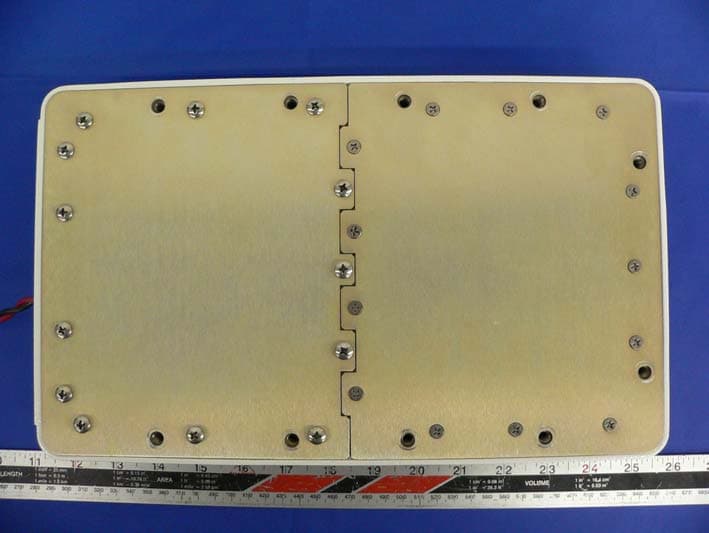
Click to zoom
Application Details
- Equipment Class
- TNB - Licensed Non-Broadcast Station Transmitter
- Date of Grant
- Dec 21, 2005
- Application Purpose
- Original Equipment
- Date of Application
- Dec 21, 2005
- Equipment Note
- Satellite Earth Station Equipment
- Frequency Range
- 1626.50000000 - 1660.50000000
- Company
- Wireless Matrix Corporation
- Country
- United States
Documents & Files
Document Text
Text extracted from the exhibit documents filed with the FCC. Open a document above to read the original.
Users Manual
Wireless Matrix SDT-5000 Installation and User Guide Wireless Matrix SDT-5000 Installation and User Guide Doc. 020-331-0002v1.1 2/31 Wireless Matrix SDT-5000 Installation and User Guide Copyright © 2005 Wireless Matrix. All rights reserved. Printed in the United States of America Created On: 11-17-05 This document is proprietary to Wireless Matrix Corporation. Do not reproduce, use or disclose without permission. We have made every effort to ensure the accuracy of all information contained in this document. However, Wireless Matrix Corporation makes no expressed or implied warranty or representation based upon the enclosed information. Wireless Matrix SDT-5000 Installation and User Guide Doc. 020-331-0002v1.1 3/31 WIRELESS MATRIX SDT-5000 INSTALLATION AND USER GUIDE TABLE OF CONTENTS SAFETY PRECAUTIONS 4 INTRODUCTION 7 TECHNICAL SUPPORT 7 PRE-INSTALLATION CONSIDERATIONS 8 General Considerations 8 Mounting Recommendations 9 Site Selection 9 Power Requirements 9 Regulatory Information 9 ANTENNA INSTALLATION 10 Attaching to a Free Standing Pole 11 Attaching to an Existing Structure (Meter Shed or Compressor Building) 11 Orientating the Antenna Using a Compass 12 Connecting the Cable to the SDT-5000 14 Cable Selection 14 Cable Assembly 14 Mating the Cable to the Junction Box 14 Aiming the Antenna 16 Using the Multi-meter and the RSSI to Aim the SDT-5000 16 Using an RS232 Connection and Terminal Program to Aim the SDT-5000 17 Status Line 21 Operational States 22 Sending a Test Message 25 SDT-5000 System Verification List 28 Trouble Shooting 28 WARRANTY 30 SDT-5000 COMPONENT LIST 31 Wireless Matrix SDT-5000 Installation and User Guide Doc. 020-331-0002v1.1 4/31 Safety Precautions Read and understand the entire manual and follow the safety instructions WARNING! 1. Replace fuse with same type and rating for protection against fire and damage. 2. The SDT-5000 is a Radio Frequency (RF) generating device. Do not operate the unit when anyone is in the vicinity noted in the Safety Information section of this guide. This could result in personal injury. 3. Do NOT operate the SDT-5000 unit in areas where explosives are in use as the RF frequency could interfere with the operation, causing hazardous conditions. Do NOT operate the SDT-5000 unit in areas where two-way radio communications is prohibited. 4. For safety purposes, use caution when determining the SDT-5000 installation location. CAUTION! 1. READ THIS MANUAL IN ITS ENTIRETY! 2. Keep all original Packing Materials. 3. Follow the instruction enumerated in the Installation Section of this guide to ensure proper hardware installation. 4. Ensure that the SDT-5000 is installed in a location that will NOT affect the RF transmission. 5. Pay close attention to the electrical power installation requirements described in this guide. Wireless Matrix SDT-5000 Installation and User Guide Doc. 020-331-0002v1.1 5/31 Safety Information Read and understand the complete Installation Guide, including the Safety Precautions, prior to using the SDT-5000 Modem. The SDT-5000 is a radio unit used to receive and transmit data. When in operation, the SDT-5000 transmits and receives RF signals to and from a Geo-stationary orbital satellite. Follow appropriate guidelines when installing the SDT-5000 near hazardous locations. As defined in ANSI/ISA Standard S82.01, Electric and Electronic Test, Measuring, Controlling, and Related Equipment, General Requirements. All electrical wiring and grounding must comply with National Electrical Code requirements and local inspection authorities. Metal enclosures and exposed metal parts of electrical instruments must be grounded in accordance with OSHA rules and regulations pertaining to Design Safety Standards for Electrical Systems, 29 CFR, Part 1910, Subject S, dated 16 April 1981 (OSHA rulings agree with the National Electric Code). The unit must be installed in an unclassified area outside the Class I, Division 2, hazardous classified location as defined by ANSI/API RP 500 – 1998 Recommended Practice for Classification of Locations for Electrical Installations at Petroleum Facilities Classified as Class I, Division 1 and Division 2. The enclosure is designed so it is sealed at all times to protect from accidental electrical shock. The SDT-5000 must be used in accordance with the safety guidelines stated in this document. Failure to comply could result in physical harm and can be a hazard to the health of the operator of this unit. Wireless Matrix SDT-5000 Installation and User Guide Doc. 020-331-0002v1.1 6/31 Important Safety Notice The SDT-5000 satellite radio emits radio frequency (RF) energy when transmitting. Operators should maintain a safe distance from radio when transmitting. The safe distance of 20 cm is measured from the center of the antenna beam with respect to the ANSI/IEEE C95.1-1992 standard. The SDT-5000 uses a directional antenna. In the case of this antenna, the 20 cm distance should be maintained under the following conditions: The antenna is powered on and transmitting. The SDT-5000 transmits only when the remote terminal unit (RTU) sends messages to the host computer. These transmission periods are typically less than 10 seconds. Otherwise, the SDT-5000 remains in receive mode or sleep mode and does not emit RF energy. A person is blocking line-of-sight to the satellite during transmission. The satellite is 101° longitudes and the antenna will point in that direction at all times while in operation. A person must be exposed to transmissions, as described above, for a continuous period of at least thirty minutes to exceed recommended exposure limits set by the Federal Communications Commission. The SDT-5000 must be mounted a minimum distance of 20 cm away from all persons and must not be co-located or operating in conjunction with any other antenna. Wireless Matrix SDT-5000 Installation and User Guide Doc. 020-331-0002v1.1 7/31 Wireless Matrix SDT-5000 Installation and User Guide Introduction Th…
Text truncated - open the document above for the full version.
Cover Letter(s)
Federal Communications Commission Authorization and Evaluation Division November 15, 2005 Confidentiality Request regarding application for certification of FCC ID: P5ISDT5 Pursuant to Sections 0.457 and 0.459 of the Commission’s Rules, we hereby request confidential treatment of information accompanying this application as outlined below: 1) Block Diagram 2) Schematics / Circuit Diagrams 3) Parts Lists and Tune-Up Procedure 4) Operational Description The above materials contain trade secrets and proprietary information not customarily released to the public. The public disclosure of these materials may be harmful to the applicant and provide unjustified benefits to its competitors. The applicant understands that pursuant to Section 0.457 of the Rules, disclosure of this application and all accompanying documentation will not be made before the date of the Grant for this application. Sincerely, Al Milligan Executive VP, Wireless Matrix USA, Inc.
External Photos
Wireless Matrix USA, Inc. FCC ID: P5ISDT5 Report # R0511175Exhibits FCC Part 25 Test Report EXHIBIT C - EUT PHOTOGRAPHS EUT Front View EUT Bottom View Wireless Matrix USA, Inc. FCC ID: P5ISDT5 Report # R0511175Exhibits FCC Part 25 Test Report EUT – Port View
ID Label/Location Info
EXHIBIT A - FCC ID LABEL INFORMATION Proposed FCC ID Label Proposed Label Location on EUT Rear Side of the EUT / Label Location FCC ID: P5ISDT5 Industry Canada Industrie Canada IC: 1478A-SDT5
Internal Photos
Wireless Matrix USA, Inc. FCC ID: P5ISDT5 Report # R0511175Exhibits FCC Part 25 Test Report EUT – Cover off View EUT –Daughter Component View Wireless Matrix USA, Inc. FCC ID: P5ISDT5 Report # R0511175Exhibits FCC Part 25 Test Report EUT –Main board Component View EUT –Power Component View Wireless Matrix USA, Inc. FCC ID: P5ISDT5 Report # R0511175Exhibits FCC Part 25 Test Report EUT –Daughter Board Solder View EUT – Main Board Solder View Wireless Matrix USA, Inc. FCC ID: P5ISDT5 Report # R0511175Exhibits FCC Part 25 Test Report EUT –Power Board Solder View Antenna – cover off View Wireless Matrix USA, Inc. FCC ID: P5ISDT5 Report # R0511175Exhibits FCC Part 25 Test Report Antenna – Close View
Operational Description
Antenna Characteristics SDT 5000 050-002-0024R01 WIRELESS MATRIX CORP. PROPRIETARY AND CONFIDENTIAL November 17TH 2005 Wireless Matrix Corporation 050-002-0024 SDT 5000 Antenna Characteristics The SDT5000 uses an integral Dual Patch, medium gain, right-hand circularly polarized antenna with a maximum gain of 11.7dBi, over the entire transmit band including cable loss. Over the receive band the gain is 10dBi. The antenna noise temperature is typically 85K @ 35° elevation. The beam -3dB bandwidth in elevation is approximately 40°, ( + - 20° from the boresight of the antenna). The azimuth -3dB bandwidth is 62°, ( + -31° from the boresight of the antenna). The antenna pattern plots are attached for reference, see Figure 1 to Figure 4. Figure 1 Dual Patch Antenna - Receive Gain Wireless Matrix Corp Proprietary and Confidential Wireless Matrix Corporation 050-002-0024 Dual patch (low profile) RX band - 1525 MHz 20, 40 and 60 degree elevation -25 -20 -15 -10 -5 0 -180-90090180 Azimuth [degrees] Gain [dB] 20 40 60 Figure 2 Typical Dual Patch Antenna Receive Azimuth Plot relative to boresight gain for various elevation angles Wireless Matrix Corp Proprietary and Confidential Wireless Matrix Corporation 050-002-0024 DUAL PATCH ANTENNA Figure 3 Dual Patch Antenna Transmit Gain Wireless Matrix Corp Proprietary and Confidential Wireless Matrix Corporation 050-002-0024 Dual patch (low profile) TX band - 1643.5 MHz 20, 40 and 60 degree elevation -25 -20 -15 -10 -5 0 -180-90090180 Azimuth [degrees] Gain [dB] 20 40 60 Figure 4 Typical Dual Patch Antenna Transmit Azimuth Plot relative to boresight gain for various elevation angles Wireless Matrix Corp Proprietary and Confidential
Operational Description
TECHNICAL SPECIFICATION SDT 5000 050-002-0025R01 WIRELESS MATRIX CORP. PROPRIETARY AND CONFIDENTIAL November 18TH 2005 Wireless Matrix Corporation 050-002-0025R01 SDT5000 Technical Specifications Receive Frequency: 1525 MHz to 1559 MHz Transmit Frequency: 1626.5 MHz to 1660.5 MHz Transmit Power into Antenna: +34 dBm Modulation: QPSK root-raised-cosine, roll-off factor = 1.6. (6.75Kb/s data rate) Frequency Stability: fc +/- 100 Hz max (transmit frequency is frequency locked to received satellite signal) Antenna Gain: 11.7dB max Power Requirements: Nominal 13.6VDC, 9VDC to 22VDC Wireless Matrix Corporation Proprietary and Confidential
RF Exposure Info
§1.1307(b)(1) & §2.1091 - RF EXPOSURE According to §1.1307(b)(1), systems operating under the provisions of this section shall be operated in a manner that ensures that the public is not exposed to radio frequency energy level in excess of the Commission’s guidelines. According to §1.1310 and §2.1091 RF exposure is calculated. Limits for General Population/Uncontrolled Exposure Frequency Range (MHz) Electric Field Strength (V/m) Magnetic Field Strength (A/m) Power Density (mW/cm 2 ) Averaging Time (minute) Limits for General Population/Uncontrolled Exposure 0.3-1.34 614 1.63 *(100) 30 1.34-30 824/f 2.19/f *(180/f 2 ) 30 30-300 27.5 0.073 0.2 30 300-1500 / / f/1500 30 1500-100,000 / / 1.0 30 f = frequency in MHz * = Plane-wave equivalent power density MPE Prediction Predication of MPE limit at a given distance Equation from page 18 of OET Bulletin 65, Edition 97-01 S = PG/4πR² Where: S = power density P = power input to antenna G = power gain of the antenna in the direction of interest relative to an isotropic radiator R = distance to the center of radiation of the antenna Maximum peak output power at antenna input terminal: 34.37(dBm ) Maximum peak output power at antenna input terminal: 2735.3 (mW) Predication frequency: 1600 (MHz) Antenna Gain (typical): 11.7(dBi) Antenna gain: 14.8 (numeric) Power Density at Prediction Distance: 1 (mW/cm 2 ) Predication Distance: 56.76 cm MPE limit for uncontrolled exposure at prediction frequency: 1.0 (mW/cm 2 ) Test Result The EUT is a mobile device. The predication distance is 56.76 cm.
Test Report
Wireless Matrix USA, Inc. FCC ID: P5ISDT5 Report # R0511175Exhibits FCC Part 25 Test Report APPENDIX E - Frequency Accuracy and stability test Wireless Matrix USA, Inc. FCC ID: P5ISDT5 Report # R0511175Exhibits FCC Part 25 Test Report Wireless Matrix USA, Inc. FCC ID: P5ISDT5 Report # R0511175Exhibits FCC Part 25 Test Report Wireless Matrix USA, Inc. FCC ID: P5ISDT5 Report # R0511175Exhibits FCC Part 25 Test Report Wireless Matrix USA, Inc. FCC ID: P5ISDT5 Report # R0511175Exhibits FCC Part 25 Test Report
Test Report
Wireless Matrix USA, Inc. FCC ID: P5ISDT5 Report # R0511175Exhibits FCC Part 25 Test Report APPENDIX D – GLONASS & MSAT BAND (1600-1610MHZ AND 1525- 1600MHZ) NOISE AND SPURIOUS TEST Wireless Matrix USA, Inc. FCC ID: P5ISDT5 Report # R0511175Exhibits FCC Part 25 Test Report Wireless Matrix USA, Inc. FCC ID: P5ISDT5 Report # R0511175Exhibits FCC Part 25 Test Report Wireless Matrix USA, Inc. FCC ID: P5ISDT5 Report # R0511175Exhibits FCC Part 25 Test Report Wireless Matrix USA, Inc. FCC ID: P5ISDT5 Report # R0511175Exhibits FCC Part 25 Test Report Wireless Matrix USA, Inc. FCC ID: P5ISDT5 Report # R0511175Exhibits FCC Part 25 Test Report Wireless Matrix USA, Inc. FCC ID: P5ISDT5 Report # R0511175Exhibits FCC Part 25 Test Report Wireless Matrix USA, Inc. FCC ID: P5ISDT5 Report # R0511175Exhibits FCC Part 25 Test Report
Test Report
Wireless Matrix USA, Inc. FCC ID: P5ISDT5 Report # R0511175Exhibits FCC Part 25 Test Report APPENDIX F- Wireless Matrix USA, Inc. FCC ID: P5ISDT5 Report # R0511175Exhibits FCC Part 25 Test Report Wireless Matrix USA, Inc. FCC ID: P5ISDT5 Report # R0511175Exhibits FCC Part 25 Test Report Wireless Matrix USA, Inc. FCC ID: P5ISDT5 Report # R0511175Exhibits FCC Part 25 Test Report
Test Report
Note: The test report is specially limited to the use of the above client company and this particular sample only. It may not be duplicated without prior written consent of Bay Area Compliance Laboratory Corporation. This report must not be used by the client to claim product certification, approval, or endorsement by NVLAP, NIST or any agency of the U.S. Government. FCC PART 25 TYPE APPROVAL EMI MEASUREMENT AND TEST REPORT For Wireless Matrix USA, Inc. 12369-B Sunrise Valley Drive Reston, VA 20191 FCC ID: P5ISDT5 This Report Concerns: Original Report Equipment Type: Satellite Earth Station equipment Test Engineer: Snell Leong Report No.: R0511175 Report Date: 2005-12-9 Reviewed By: Richard Lee Prepared By: Bay Area Compliance Laboratory Corporation (BACL) 230 Commercial Street Sunnyvale, CA 94085 Tel: (408) 732-9162 Fax: (408) 732 9164 Wireless Matrix USA, Inc. FCC ID: P5ISDT5 Report # R0511175Rpt Page 2 of 26 FCC Part 25 Test Report TABLE OF CONTENTS GENERAL INFORMATION.......................................................................................................................................4 PRODUCT DESCRIPTION FOR EQUIPMENT UNDER TEST (EUT) ....................................................................................4 OBJECTIVE...................................................................................................................................................................4 RELATED SUBMITTAL(S)/GRANT(S).............................................................................................................................4 TEST METHODOLOGY..................................................................................................................................................4 TEST FACILITY.............................................................................................................................................................4 SYSTEM TEST CONFIGURATION ..........................................................................................................................6 JUSTIFICATION.............................................................................................................................................................6 EUT EXERCISE SOFTWARE..........................................................................................................................................6 SPECIAL ACCESSORIES.................................................................................................................................................6 SCHEMATICS / BLOCK DIAGRAM.................................................................................................................................6 EQUIPMENT MODIFICATIONS.......................................................................................................................................6 LOCAL SUPPORT EQUIPMENT LIST AND DETAILS........................................................................................................6 EXTERNAL I/O CABLING LIST AND DETAILS...............................................................................................................6 CONFIGURATION OF TEST SYSTEM..............................................................................................................................7 TEST SETUP BLOCK DIAGRAM.....................................................................................................................................7 SUMMARY OF TEST RESULTS ...............................................................................................................................8 §2.1047 – MODULATION CHARACTERISTICS ....................................................................................................9 §2.1051 – SPURIOUS EMISSIONS AT ANTENNA TERMINALS .......................................................................10 STANDARD APPLICABLE............................................................................................................................................10 MEASUREMENT PROCEDURE......................................................................................................................................10 NOTE: THE RBW WAS SET TO 10KHZ INSTEAD OF 4KHZ, IF THE TEST RESULT COMPLIED WITH 10KHZ RESOLUTION BANDWIDTH , IT DEEM TO COMPLY FOR 4KHZ . ..........................................................................................................10 EQUIPMENT LISTS......................................................................................................................................................10 MEASUREMENT RESULT............................................................................................................................................10 §15.107 - CONDUCTED EMISSIONS ......................................................................................................................15 MEASUREMENT UNCERTAINTY..................................................................................................................................15 EUT SETUP................................................................................................................................................................15 RECEIVER SETUP........................................................................................................................................................15 TEST EQUIPMENT LIST AND DETAILS.........................................................................................................................15 TEST PROCEDURE......................................................................................................................................................15 TEST RESULTS SUMMARY..........................................................................................................................................16 CONDUCTED EMISSIONS TEST DATA........................…
Text truncated - open the document above for the full version.
Test Setup Photos
Wireless Matrix USA, Inc. FCC ID: P5ISDT5 Report # R0511175Exhibits FCC Part 25 Test Report EXHIBIT B - TEST SETUP PHOTOGRAPHS Conducted Emission-Front View Conducted Emission-Rear View Wireless Matrix USA, Inc. FCC ID: P5ISDT5 Report # R0511175Exhibits FCC Part 25 Test Report Radiated Setup – Transmitter
Contact Information
Applicant
Darryl Strucko(P.E., Sr. Systems Engineer)
Test Firm
Bay Area Compliance LaboratoryJohn Chan
Technical Specifications
| # | Rule Parts | Frequency Range | Power Output | Emission | Tolerance |
|---|---|---|---|---|---|
| 1 | 25 | 1.63 GHz - 1.66 GHz | 40.46 W | 4K39DXD | 2.5000000000 ppm |
Other Applications from Wireless Matrix Corporation
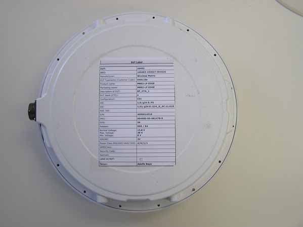
P5IMBS2LPE
Dec 10, 2006Mobile base station with L-Band Sat, GSM and WLAN
Equipment Class
TNB - Licensed Non-Broadcast Station Transmitter
P5IMBS2LP
Nov 18, 2005Mobile base station with L-Band Sat, GSM and WLAN
Equipment Class
PCB - PCS Licensed Transmitter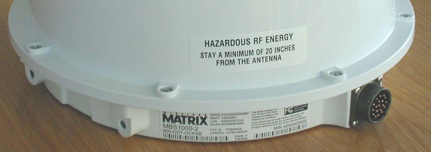
P5IMBS2A
Mar 25, 2004Mobile base station with L-Band Sat, GSM and WLAN
Equipment Class
TNB - Licensed Non-Broadcast Station Transmitter
P5I-907-FNN-A
Apr 07, 2002Wireless Telemetry Unit with RIM 802 DataTAC Radio
Equipment Class
TNB - Licensed Non-Broadcast Station Transmitter