P5ROEM176SACRFID Reader and Barcode Scanner Module
I2R Ltd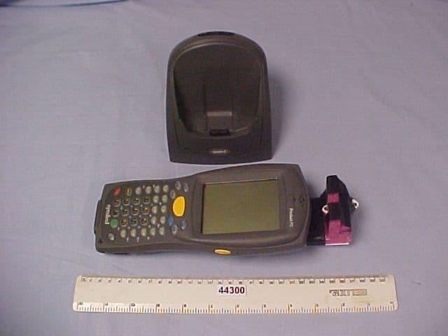
Click to zoom
Application Details
- Equipment Class
- DXT - Part 15 Low Power Transceiver, Rx Verified
- Date of Grant
- Jun 25, 2003
- Application Purpose
- Original Equipment
- Date of Application
- Jun 25, 2003
- Equipment Note
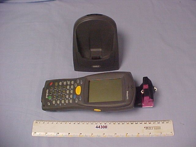
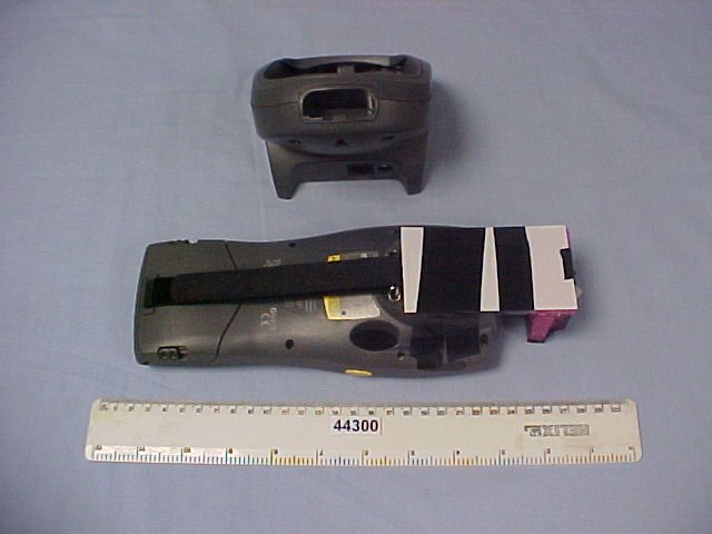
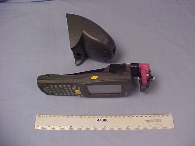
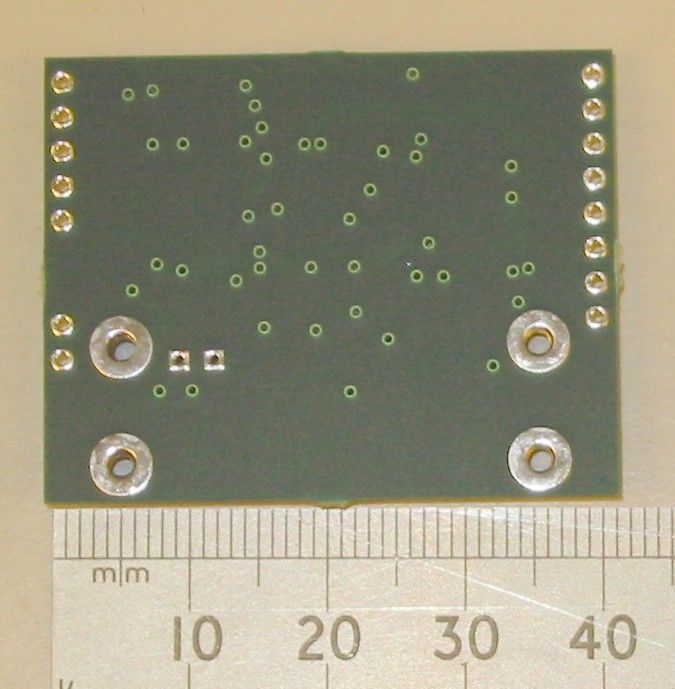
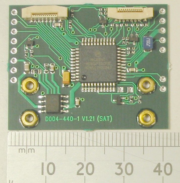
- RFID Reader and Barcode Scanner Module
- Frequency Range
- 0.13420000 - 0.13420000
- Company
- I2R Ltd
- Country
- United Kingdom
Documents & Files
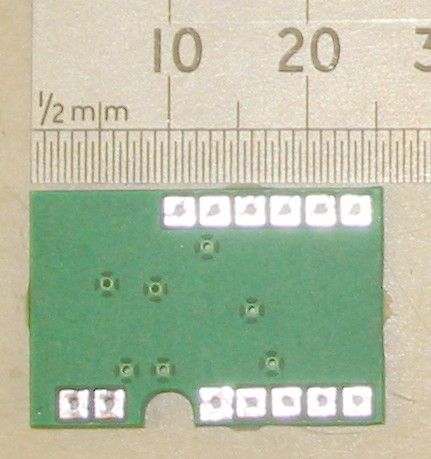
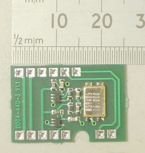
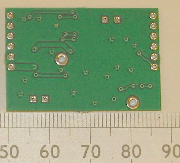
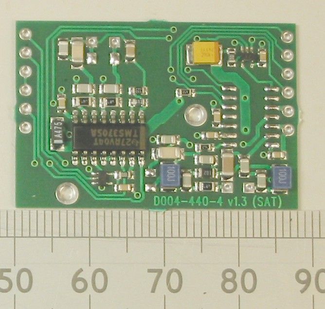
Document Text
Text extracted from the exhibit documents filed with the FCC. Open a document above to read the original.
Users Manual
335429.DOC STRICTLY CONFIDENTIAL DO NOT COPY The information contained in this document is the property of Sirit Technologies INC. and cannot be communicated to Third parties or reproduced without the written consent of Sirit Technologies. Sirit Technologies reserves the right to change its products, specifications and services at any time without notice. User Manual Information OEM 176-177 (LF-MTE) Sirit Technologies Ltd Loughborough Technology Centre Epinal Way Loughborough Leicestershire LE11 3GE Tel: +44 (0) 1509 213141 Fax: +44 (0) 1509 213191 Email: [email protected] Loughborough Technology Centre Epinal Way Loughborough Leicestershire LE11 3GE. Tel: +44 1509 213141 Fax: +44 1509 213191 Email: [email protected] Page 2 of 4 This document is for information only. Every effort has been made to avoid errors, but Sirit provide no guarantee as to the accuracy of the material. History Version 1.0 – First release 4 th of June 2003 1 Introduction Sirt Technologies Ltd. is a wholly owned UK subsidiary of Sirit Technologies inc. of Toronto Canada and forms the design and development arm of the corporation. This company was formerly known as I2r Ltd. This document covers the User Manual Information of the OEM 176 / 177 combined RFID and bar-code scanner module when fitted to the Colour screen version Symbol 8146 UL approved hand held computer. There is no specific document “User Manual” this is because the module is completely transparent to the end user.
Cover Letter(s)
10/6/2003 Telecommunication Certification Body Radio Frequency Investigation Ltd. Ewhurst Park Ramsdell Basingstoke Hampshire RG26 5RQ England Subject: Certification Application FCC ID: P5EOEM176SAC It is requested that the following information is to be held confidential on behalf of Applicants Name. FCC Rules Part 0.459 refers. Circuit Schematics 5 files 1-3 pages per file OEM 176-177 (LF-MTE) BOTTOM BOARD CIRCUIT DIAGRAM.pdf (2 pages) OEM 176-177 (LF-MTE) LEFT BOARD CIRCUIT DIAGRAM.pdf (1 page) OEM 176-177 (LF-MTE) RIGHT BOARD CIRCUIT DIAGRAM.pdf (1 page) OEM 176-177 (LF-MTE) TOP BOARD CIRCUIT DIAGRAM.pdf (3 pages) OEM 176-177 (LF-MTE) BLOCK DIAGRAM.pdf (1 page) Bil of Materials 1 file 5 page per file OEM 176-177 (LF-MTE) BILL OF MATERIALS (SAT COLOUR).XLS This device is unique in the market place, as such this information is commertialy very sensitive. The disclosure of this information would allow our competitors to gain an advantage in the market place. The product is manufactured in house therefire this information is retained in house in a secure storage area and is not available to the public.
Operational Description
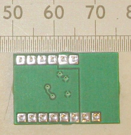
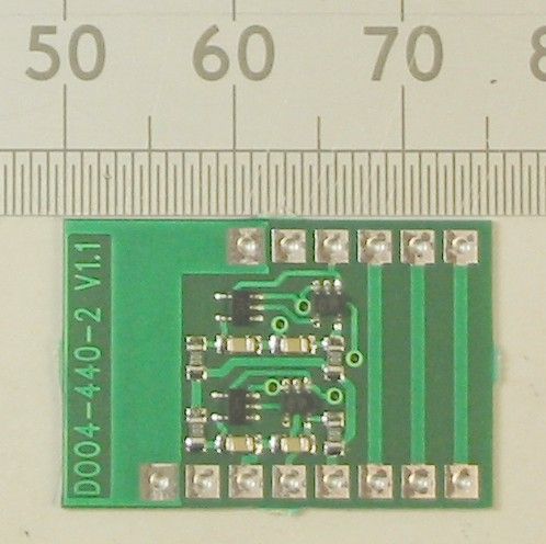
335420.DOC STRICTLY CONFIDENTIAL DO NOT COPY The information contained in this document is the property of Sirit Technologies INC. and cannot be communicated to Third parties or reproduced without the written consent of Sirit Technologies. Sirit Technologies reserves the right to change its products, specifications and services at any time without notice. Operational Description of OEM 176-177 (LF-MTE) Sirit Technologies Ltd Loughborough Technology Centre Epinal Way Loughborough Leicestershire LE11 3GE Tel: +44 (0) 1509 213141 Fax: +44 (0) 1509 213191 Email: [email protected] Loughborough Technology Centre Epinal Way Loughborough Leicestershire LE11 3GE. Tel: +44 1509 213141 Fax: +44 1509 213191 Email: [email protected] Page 2 of 4 This document is for information only. Every effort has been made to avoid errors, but Sirit provide no guarantee as to the accuracy of the material. History Version 0.1 – Document created Version 1.0 – First release 24 th of February 2003 Version 2.0 – updated 10 th June 2003 1 Introduction Sirit Technologies Ltd. is a wholly owned UK subsidiary of Sirit Technologies inc. of Toronto Canada and forms the design and development arm of the corporation. This document covers the Operational description of the OEM 176 / 177 combined RFID and bar-code scanner module when fitted to the Symbol 8146 UL approved, colour screen, hand held computer. The OEM 177 is the version of this module, which is RFID equipped only and is not fitted in this case. The module occupies the same space envelope as the Symbol Technologies SE1223 Bar-code scan engine and when replaced by the OEM176 / 177 gives the combined RFID and bar-code function by utilising the Symbol SE923 ultra miniature bar-code scanner with the RFID components mounted around it. The interface to the 8146 directly emulates that of the bar-code scan engine with the addition of RFID commands. Loughborough Technology Centre Epinal Way Loughborough Leicestershire LE11 3GE. Tel: +44 1509 213141 Fax: +44 1509 213191 Email: [email protected] Page 3 of 4 This document is for information only. Every effort has been made to avoid errors, but Sirit provide no guarantee as to the accuracy of the material. 2 Functional Description Refer to the block diagram The Symbol 8146 Colour handheld computer in which the module is mounted supplies regulated +5VDC power to the module. The 8146 has the ability to shut off power to the module so as to extend battery life when not in use. The module can operate in a further low power mode; in the “module” low power mode the module shuts off most of its internal circuitry after about 1 second of inactivity on either any of its 4 “Wake Up” lines or it does not receive a command on the serial interface from the Symbol 8146. In the standard power mode all circuitry remains active and power control is via the 8146 both normal and low power modes are software selectable. The micro-controller mounted on the bottom PCB receives a master clock signal of 16MHz from the crystal oscillator circuit mounted on the right-hand PCB. This signal is divided by 4 on the left hand PCB to produce a 4MHz signal that is fed to the Top PCB which contains the RFID circuitry. Each of the RFID ASICs (Application Specific Integrated Circuits) is dedicated to one of the two RFID frequencies used by this module, 125kHz and 134.2kHz. (In this particular version of the module the 125kHz ASIC is not used and is not fitted). The 4MHz signal is gated to both ASICs to further reduce power consumption and to reduce the possibility of both ASICs transmitting at the same time. Each of the ASICs derives its carrier frequency by internally dividing the 4 MHz clock fed to it. 134.2Khz The 134.2kHz ASIC will only “come to life” when commanded by the micro controller which communicates with the ASIC via a bi-directional serial data link. Upon receiving a command to communicate with a RFID tag, a 134.2kHz carrier is generated in the ASIC, the carrier signal is amplified by the PA stage and is fed to the external resonating and matching circuit. The antenna is a 400μH coil is constructed to fit around the inside face of the 8146 bar-code window. This antenna coil is series resonated to 134.2kHz by a close tolerance capacitor. Other components around this circuit are fitted to reduce EMC and to provide additional protection to the ASIC. Loughborough Technology Centre Epinal Way Loughborough Leicestershire LE11 3GE. Tel: +44 1509 213141 Fax: +44 1509 213191 Email: [email protected] Page 4 of 4 This document is for information only. Every effort has been made to avoid errors, but Sirit provide no guarantee as to the accuracy of the material. RFID tags operating on the 134.2kHz frequency work on the half duplex principle that is the transmitter sends out a “Power pulse” (which may or may not contain modulation depending on the required tag response) and the tag absorbs energy during the “power pulse” then responds by transmitting a signal back to the reader antenna in the period sfter the power pulse. The received signal is picked off the antenna coil and is fed into the receiver circuits of the ASIC. Data is received from the tag in the form off a Frequency Shift Keying (FSK) signal; this is decoded by the receiver and converted to a serial data stream, which is fed back to the micro-controller for final decoding and error checking. The fully decoded and checked data is passed back to the hand held computer by the serial data link. 125KHz This is not fitted to this version of the module but operates in a similar way to the 134.2KHz with 2 notable differences:- • The 125kHz tags operate in the full duplex (backscatter) mode i.e. they “load modulate” the carrier signal. • The tags use Amplitude Shift Keying (ASK) Not FSK. • There are a lot more different types of tags, all of which have a slightly different protocol. Bar-code Scan Engine The Symbol SE923 bar code scan engine mounted within the module is directly controlled by the …
Text truncated - open the document above for the full version.
Test Report
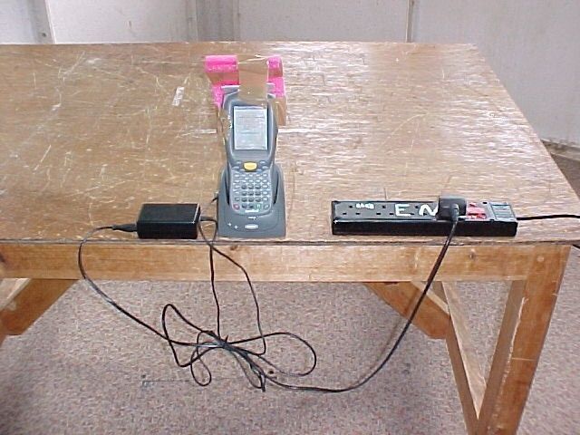
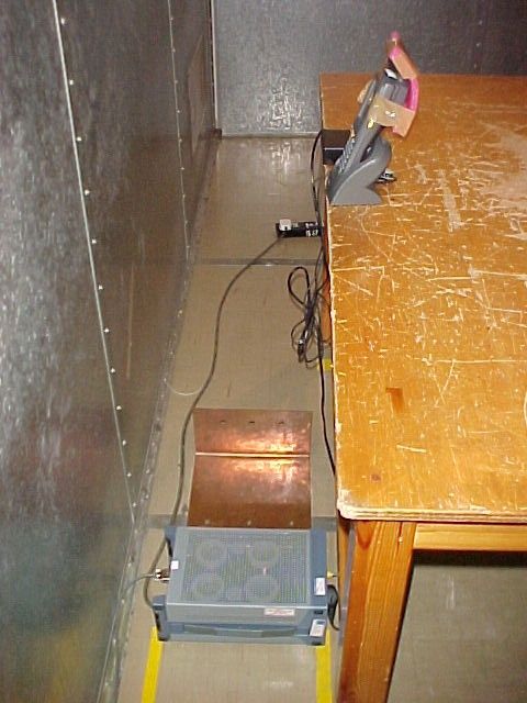
Radio Frequency Investigation Ltd, Ewhurst Park, Ramsdell, Basingstoke, Hampshire, RG26 5RQ, ENGLAND. Tel: +44 (0) 1256 851193 Fax: +44 (0) 1256 851192 Registered in England, No. 211 7901. Registered Office: Ewhurst Park, Ramsdell, Basingstoke, Hampshire RG26 5RQ TESTING 0644 TEST REPORT FROM RADIO FREQUENCY INVESTIGATION LTD. Test Of: i2r Ltd (Sirit UK). OEM176/SAT To: FCC Part 15 Subpart C: 2002 Test Report Serial No: RFI/MPTB1/RP44655JD01A This Test Report Is Issued Under The Authority Of Richard Jacklin, Operations Director: Checked By: Tested By: pp Release Version No: PDF01 Issue Date: 26 June 2003 Test Dates: 1 May 2003 This report is issued in Adobe Acrobat portable document format (PDF). It is only a valid copy of the report if it is being viewed in PDF format with the following security options not allowed: Changing the document, Selecting text and graphics, Adding or changing notes and form fields. Furthermore, the date of creation must match the issue date stated above. This report may be copied in full. The results in this report apply only to the sample(s) tested. RADIO FREQUENCY INVESTIGATION LTD. TEST REPORT S.No. RFI/MPTB1/RP44655JD01A Operations Department Page 2 of 34 Issue Date: 26 June 2003 Test Of: i2r Ltd (Sirit UK). OEM176/SAT To: FCC Part 15 Subpart C: 2002 This page has been left intentionally blank. RADIO FREQUENCY INVESTIGATION LTD. TEST REPORT S.No. RFI/MPTB1/RP44655JD01A Operations Department Page 3 of 34 Issue Date: 26 June 2003 Test Of: i2r Ltd (Sirit UK). OEM176/SAT To: FCC Part 15 Subpart C: 2002 Table of Contents 1. Client Information..........................................................................................................4 2. Equipment Under Test (EUT) .......................................................................................5 3. Test Specification, Methods And Procedures ............................................................7 4. Deviations From The Test Specification .....................................................................9 5. Operation Of The EUT During Testing ......................................................................10 6. Summary Of Test Results...........................................................................................11 7. Measurements, Examinations And Derived Results................................................12 8. Measurement Uncertainty ..........................................................................................18 Appendix 1. Test Equipment Used ................................................................................19 Appendix 2. Measurement Methods ..............................................................................20 Appendix 3. Test Configuration Drawings....................................................................23 Appendix 4. Graphical Test Results ..............................................................................27 RADIO FREQUENCY INVESTIGATION LTD. TEST REPORT S.No. RFI/MPTB1/RP44655JD01A Operations Department Page 4 of 34 Issue Date: 26 June 2003 Test Of: i2r Ltd (Sirit UK). OEM176/SAT To: FCC Part 15 Subpart C: 2002 1. Client Information Company Name: i2r Ltd (Sirit UK) Address: Unit 10 Loughborough Technology Centre Epinal Way Loughborough Leicestershire LE11 3GE Contact Name: Mr G Bishop / Mr T Weeks RADIO FREQUENCY INVESTIGATION LTD. TEST REPORT S.No. RFI/MPTB1/RP44655JD01A Operations Department Page 5 of 34 Issue Date: 26 June 2003 Test Of: i2r Ltd (Sirit UK). OEM176/SAT To: FCC Part 15 Subpart C: 2002 2. Equipment Under Test (EUT) The following information (with the exception of the Date of Receipt) has been supplied by the client: 2.1. Identification Of Equipment Under Test (EUT) Brand Name: Sirit Model Name or Number: OEM176/SAT Unique Type Identification: None stated by client Serial Number: X20000148 Country of Manufacture: UK FCC ID Number: P5ROEM176SAC Date of Receipt: 1 st May 2003 2.2. Description Of EUT The equipment under test is a dual technology laser barcode scanner & RFID Reader running at 134.2 kHz mounted in a handheld computer. 2.3. Modifications Incorporated In EUT The EUT has not been modified from what is described by the model number stated above. 2.4. Additional Information Related To Testing Power Supply Requirement: Internal battery supply of approx. 3.7V internally regulated to +5V Intended Operating Environment: Commercial / Light Industry Interface Ports: Serial data and control port internally connected to the Symbol terminal (no external connection) RADIO FREQUENCY INVESTIGATION LTD. TEST REPORT S.No. RFI/MPTB1/RP44655JD01A Operations Department Page 6 of 34 Issue Date: 26 June 2003 Test Of: i2r Ltd (Sirit UK). OEM176/SAT To: FCC Part 15 Subpart C: 2002 2.5. Support Equipment The following support equipment was used to exercise the EUT during testing: Description: Handheld Computer in which the EUT is mounted Brand Name: Symbol Model Name or Number: PDT 8146 – B2A930EU Serial Number: None stated by client FCC ID Number: None stated by client Cable Length And Type: Not applicable Connected to Port: Not applicable RADIO FREQUENCY INVESTIGATION LTD. TEST REPORT S.No. RFI/MPTB1/RP44655JD01A Operations Department Page 7 of 34 Issue Date: 26 June 2003 Test Of: i2r Ltd (Sirit UK). OEM176/SAT To: FCC Part 15 Subpart C: 2002 3. Test Specification, Methods And Procedures 3.1. Test Specification Reference: FCC Part 15: 2002 Subpart C, Sections: 15.207 and 15.209. Title: Code of Federal Regulations, Part 15 (47CFR) Radio Frequency Devices: Digital Devices. Comments: A description of the test facility used for this test is on file with, and has been accepted by, the Federal Communications Commission as required by Section 2.948 of Federal Rules. Purpose of Test: To determine whether the equipment complied with the applicable requirements of the specification for the purposes of certification. Reference: FCC Part 15: 2002 Subpart B, Sections: 15.107 and 15.109 Title: Code of Federal R…
Text truncated - open the document above for the full version.
Contact Information
Applicant
Dr. David R Evans(Managing Director)
Test Firm
RFI Global Services Ltd.Allan Hume
Technical Specifications
| # | Rule Parts | Frequency Range | Power Output | Tolerance |
|---|---|---|---|---|
| 1 | 15C | 0.1342 MHz - 0.1342 MHz | 50.00 mW | 100.0000000000 Hz |
Other Applications from I2R Ltd
P5ROEM410V12
Apr 22, 2003RFID Reader Module
Equipment Class
DXT - Part 15 Low Power Transceiver, Rx Verified
P5ROEM176SAT
Mar 12, 2003RFID Reader and Barcode Scanner Module
Equipment Class
DXT - Part 15 Low Power Transceiver, Rx Verified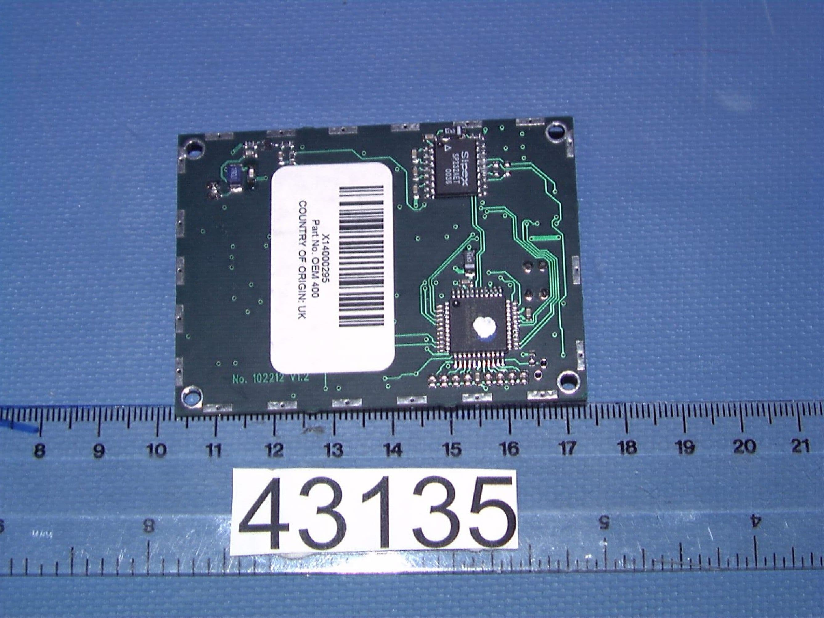
P5ROEM400V12
May 13, 2002RFID Reader Module
Equipment Class
DXT - Part 15 Low Power Transceiver, Rx Verified