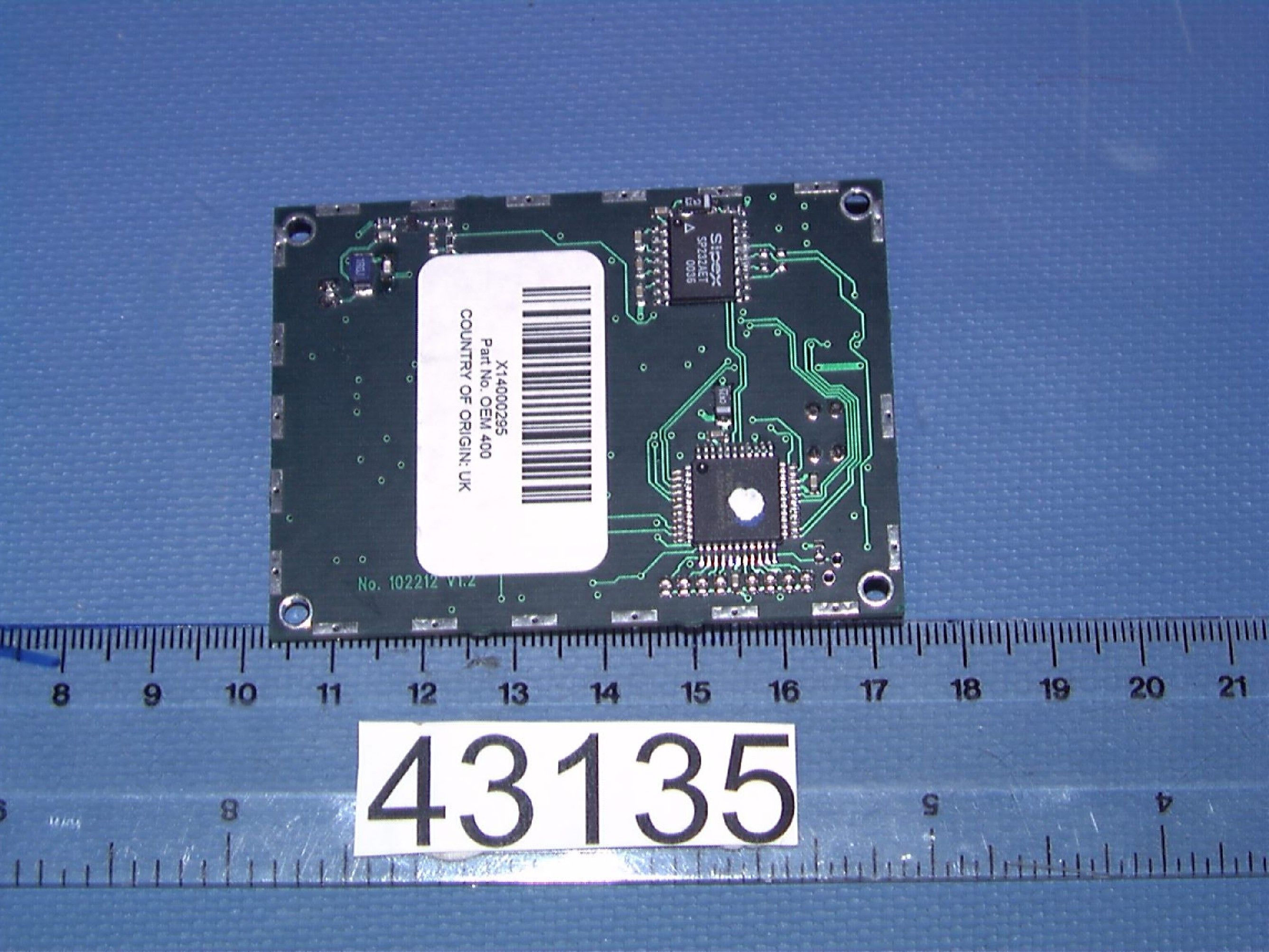
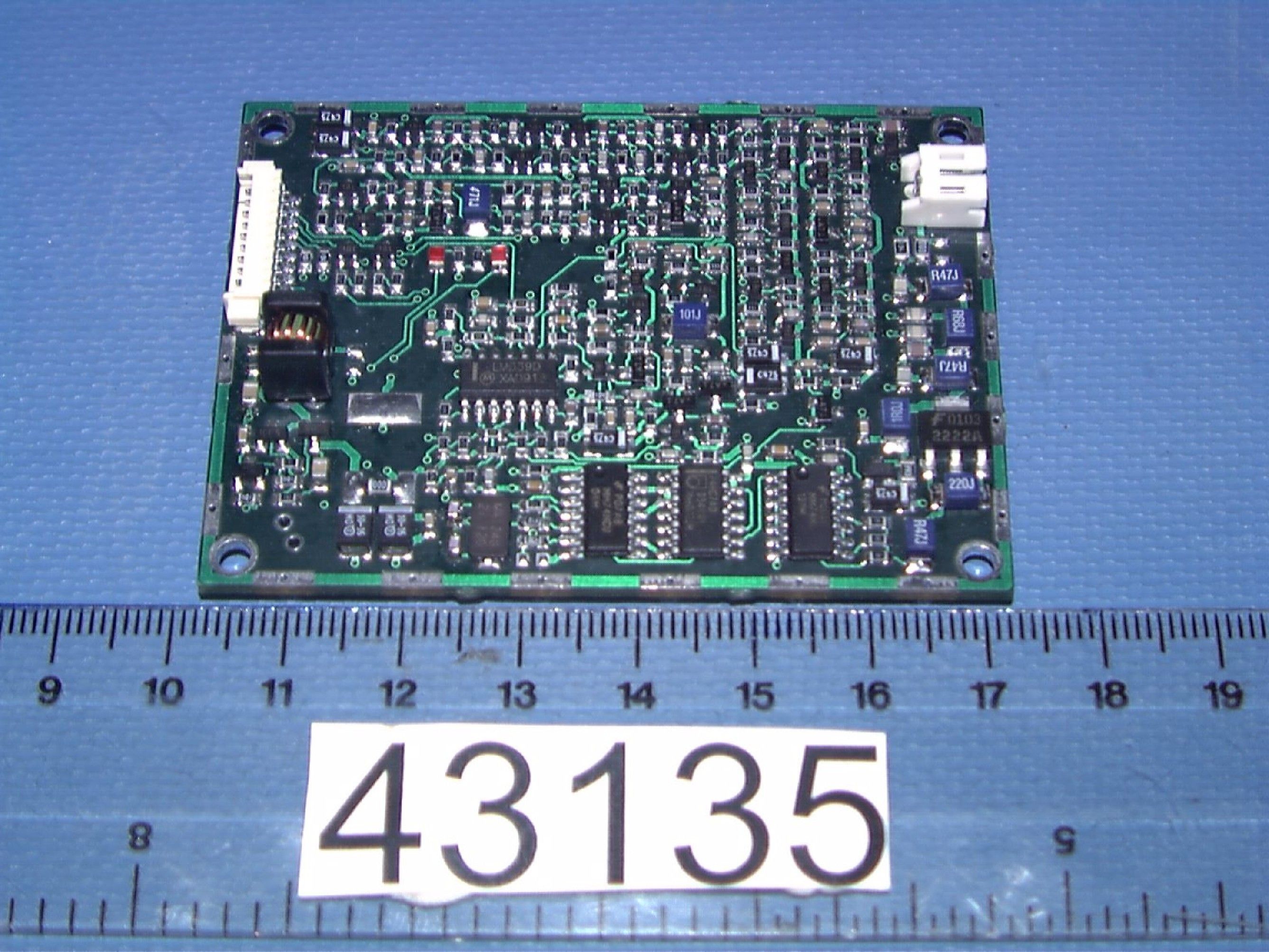
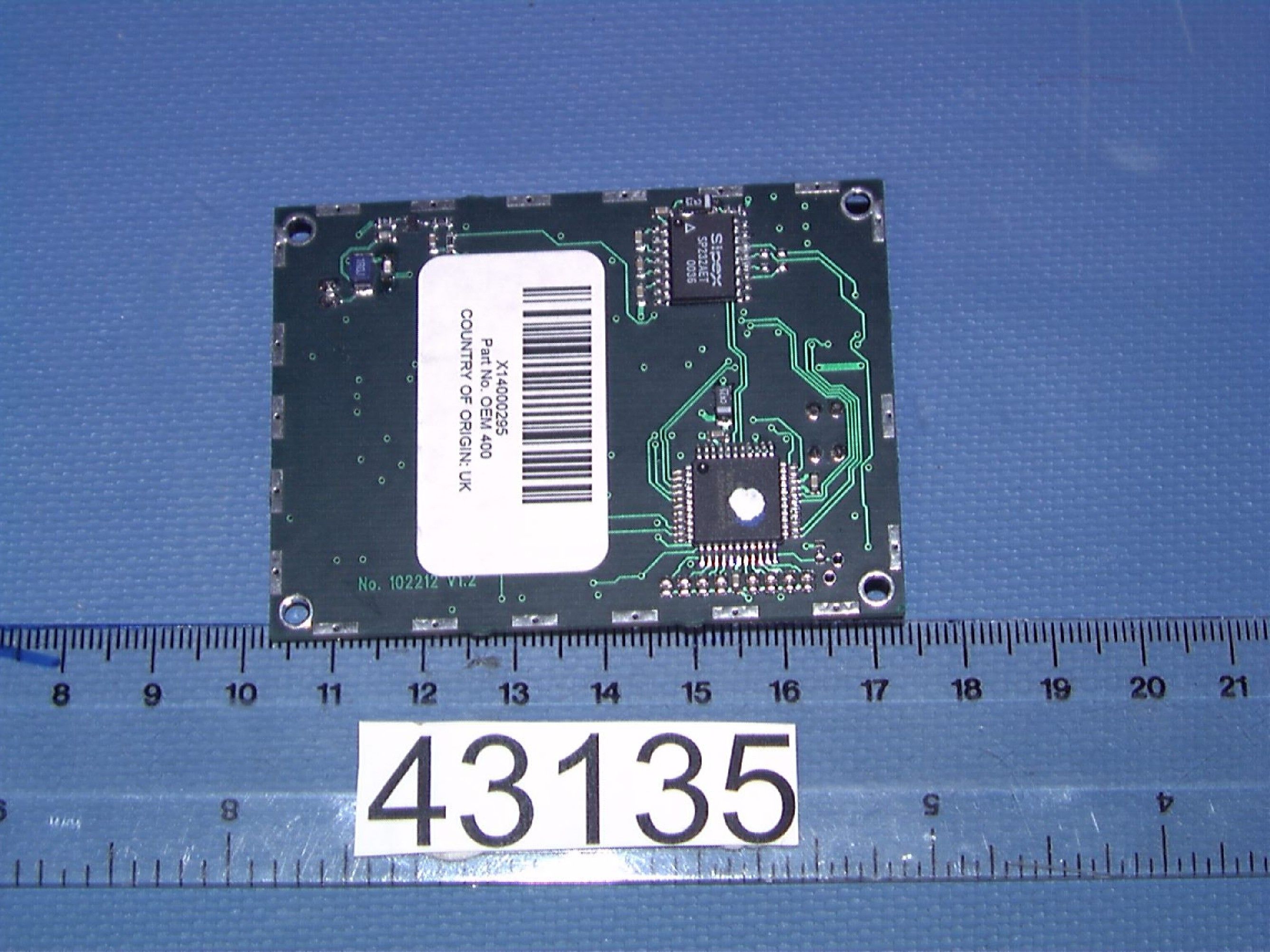
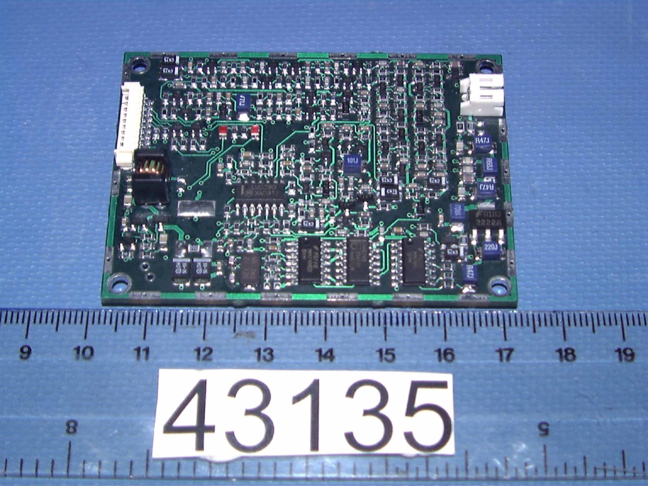
P5ROEM400V12RFID Reader Module
I2R Ltd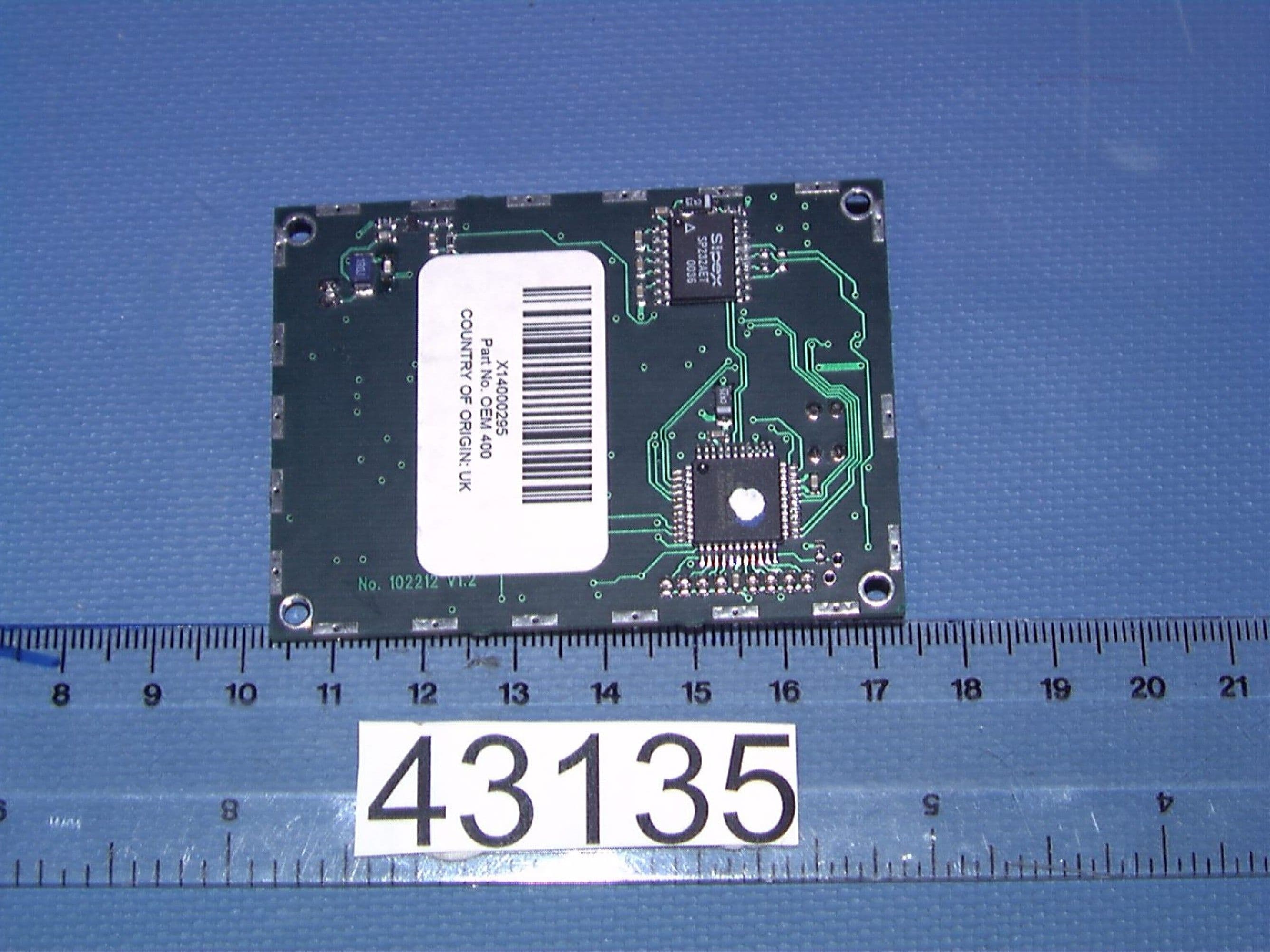
Click to zoom
Application Details
- Equipment Class
- DXT - Part 15 Low Power Transceiver, Rx Verified
- Date of Grant
- May 13, 2002
- Application Purpose
- Original Equipment
- Date of Application
- May 13, 2002
- Equipment Note
- RFID Reader Module
- Frequency Range
- 13.56000000 - 13.56000000
- Company
- I2R Ltd
- Country
- United Kingdom
Documents & Files
Document Text
Text extracted from the exhibit documents filed with the FCC. Open a document above to read the original.
Users Manual
WARNING This product provides powerful features that allow the contents of Radio Frequency IDentification (RFID) tags to be inspected, altered and (in some cases) permanently locked. It is the responsibility of the user to ensure that they are fully conversant with the wide range of features that are offered by tags supported by this product. No responsibility can, or will, be accepted by SIRIT Technologies for any tags that are corrupted or permanently locked through direct or indirect use of this product. WARRANTIES SIRIT Technologies makes no warranty of any kind with regard to the material contained in this document, including, but not limited to, implied warranties of merchantability and fitness for a particular purpose. SIRIT Technologies reserve the right to make changes, without notice, in the specifications and materials contained herein, and shall not be responsible for any damages (including consequences caused by reliance on the materials presented), including but not limited to typographic or arithmetic policy. RESTRICTIONS This document contains proprietary information, which is protected by copyright. All rights are reserved. No part of this document may be reproduced or transmitted in any form or by any means, electronic or mechanical, including photocopying, recording, or information storage and retrieval systems, without the prior written consent of SIRIT Technologies. PRODUCT WARRANTY This product is warranted against defects in materials and workmanship, under normal use and service, for one calendar year from the date of purchase, in accordance with SIRIT Technologies’ standard terms and conditions. All goods returned under this warranty must be as new and not modified in any manner. Under such conditions SIRIT Technologies’ sole responsibility shall be, at its discretion, to either repair or replace such defective products. Under no circumstances shall SIRIT Technologies be liable for any consequential direct or indirect loss of revenue or profit, caused by failure of the product. LIFE CR IT ICAL APPLIC AT IONS SIRIT Technologies’ products are not designed, intended, authorised or warranted to be suitable for life support or other life critical applications, which could involve potential or actual risk of death, personal injury or severe property or environmental damage. The use of all registered trademarks is acknowledged. Document index OEM400 Approvals...........................................................................................................................3 1Product overview........................................................................................................4 1.1Introduction..........................................................................................................4 1.2Tags supported....................................................................................................4 1.3Warranty exception..............................................................................................4 2First time operation.....................................................................................................5 2.1Introduction..........................................................................................................5 2.2Power and serial connections...............................................................................5 2.3Antenna connection..............................................................................................6 2.4Baud rate settings................................................................................................6 2.5Digital I/O............................................................................................................6 2.6Output power settings...........................................................................................7 2.7Installing and loading the SLC test software...........................................................7 2.8Powering for the first time.....................................................................................8 2.9Set-up and test....................................................................................................8 3Downloading firmware................................................................................................9 3.1Introduction..........................................................................................................9 3.2Selecting the communications port........................................................................9 3.3Selecting the firmware file and downloading...........................................................9 3.4Forcing the product into Bootloader mode............................................................ 10 4Technical specifications........................................................................................... 11 4.1Introduction........................................................................................................ 11 4.2Hardware specifications..................................................................................... 11 4.3Component locations.......................................................................................... 12 4.4Board dimensions.............................................................................................. 13 4.5Wiring diagram for D-Type connector.................................................................. 14 5Fault diagnosis......................................................................................................... 15 5.1Introduction........................................................................................................ 15 © Copyright 2002, SIRIT Technologies : Manual version 2.03 Product overview OEM400 1 Page 3 of 15 Approvals The information below relating to approvals supersedes and replaces the relevant information within this manual and must be adhered too to maintain approvals. FCC approval …
Text truncated - open the document above for the full version.
Cover Letter(s)
242819 STRICTLY CONFIDENTIAL DO NOT COPY The information contained i n this document is the property of i2R Ltd. and cannot be communicated to third parties or reproduced without the written consent of i2R Ltd. i2R reserves the right to change its products, specifications and services at any time without notice. Created on 03/21/02 12:59 PMCreated by GM Bishop Application for Limited Modular Approval (LMA) Loughborough Technology Centre Epinal Way LOUGHBOROUGH Leicestershire LE11 3GE Tel: +44 (0) 1509 213141 Fax: +44 (0) 1509 213191 Email: [email protected] 242819 Limited Modular Approval Application Page 2 of 4 Loughborough Technology Centre Epinal Way Loughborough Leicestershire LE11 3GE Tel: +44 1509 213141 Fax: +44 1509 213191 Email: [email protected] Overview The OEM-400v1.2 module is a Radio Frequency Identification (RFID) interrogator capable of reading from and writing to various 13.56MHz transponders. The OEM-400v1.2 operates under the control of a host (in this case the SATO CL408/412 printer and is designed to be integrated within the SATO printer. Limited Modular Approval (LMA) is requested to facilitate the integration of the OEM-400v1.2 and reduce the need for repeated testing. In accordance with Public Notice DA 00-1407 (June 2000) the following issues are addressed: Contents 1RF Shielding...................................................................................................................................... 3 2Data inputs......................................................................................................................................... 3 3Power Supply regulation................................................................................................................... 3 4Antenna.............................................................................................................................................. 3 5Labelling............................................................................................................................................ 3 6Specific operating requirements........................................................................................................ 4 7RF exposure requirements................................................................................................................. 4 History Version 0.1 - document creation 242819 Limited Modular Approval Application Page 3 of 4 Loughborough Technology Centre Epinal Way Loughborough Leicestershire LE11 3GE Tel: +44 1509 213141 Fax: +44 1509 213191 Email: [email protected] 1 RF Shielding This application relates to the specific incorparation of the OEM-400v1.2 into the SATO CL408/412 printer as such all tests were performing using this printer without additional screening. 2 Data inputs The OEM-400v1.2 is command driven. No RF is generated without the receipt of a valid command. Commands are received on a serial TTL level port at baud rates between 9600 baud and 57600 baud. Since the data input is digital it is not possible to cause overmodulation. Similarly an excessive data rate will prevent the command from being decoded and acted upon. 3 Power Supply regulation The OEM-400v1.2 receives its regulated power supply from the SATO printer .The installation instructions in the User Manual specify that the power supply must be regulated to 5V±5% to retain LMA; this being the range over which the module is specified and was tested. 4 Antenna All testing was performed using the custom antenna mounted in its final position within the printer. This antenna is connected to the OEM-400v1.2 via a non standard connector to avoid the possibility of a different antenna being connected. The installation instructions in the User Manual specify that the custom antenna must be used to retain LMA.. 5 Labelling The OEM400v1.2 is labelled on the bottom side of the using a self adhesive label as shown in Figure 1. 242819 Limited Modular Approval Application Page 4 of 4 Loughborough Technology Centre Epinal Way Loughborough Leicestershire LE11 3GE Tel: +44 1509 213141 Fax: +44 1509 213191 Email: [email protected] Figure 1: Design of OEM400V1.2 label (not to scale) Since this will not be visible when the OEM400V1.2 is installed in the final product the installation instructions in the User Manual specify that the final product should display a label including the text “Contains Transmitter Module FCC ID: PR5OEM400V12”. 6 Specific operating requirements There are no operating requirements for Section 15.225 that can be modified by the user. 7 RF exposure requirements There are no RF exposure implications with operating the OEM 400 V1.2
Cover Letter(s)
30/4/2002 Telecommunication Certification Body Radio Frequency Investigation Ltd. Ewhurst Park Ramsdell Basingstoke Hampshire RG26 5RQ England Subject: Certification Application FCC ID: P5ROEM400V12 It is requested that the following information is to be held co nfidential on behalf of i2R FCC Rules Part 0.459 refers. Circuit Schematics3 files1 page per file Bil of Materials OEM400v1.2 – SATO.xls 1 file3 page per file OEM-400 v1.2 Block diagram.pdf1 file1 page per file This device is unique in the market place, as such this information is commercially very sensitive. The disclosure of this information would allow our competitors to gain an advantage in the market place. The product is manufactured in ho use therefore this information is retained in house in a secure storage area and is not available to the public. Yo urs si ncer ely Gary Bishop
ID Label/Location Info
Label layout
Operational Description
19 th September 2001 STRICTLY CO NFIDENTIAL DO NOT COPY The information contained i n this document is the property of i2R Ltd. and cannot be communicated to Third parties or reproduced without the written consent of i2R Ltd. i2R reserves the right to change its products, specifications and services at any time without notice. Operatioal description of the OEM400v1.2 Loughborough Technology Centre Epinal Way LOUGHBOROUGH Leicestershire LE11 3GE Tel: +44 1509 213141 Fax: +44 1509 213191 Email: [email protected] 19th September 2001 STRICTLY CO NFIDENTIAL DO NOT COPY Page 2 of 2 Loughborough Technology Centre Epinal Way L O UG HBO RO UG H Leicestershire LE11 3GE Tel: +44 1509 213141 Fax: +44 1509 213191 Email: [email protected] The OEM-400v1.2 reader module is designed to interrogate, read and write to various Radio frequency Identification (RFID) tags operating at 13.56MHz. The unit is command driven from a host device (in this case the Sato CL408/412 printer) via a serial TTL bi-directional interface. The module is powered by an external regulated 5V power source supplied by the host device. With reference to the block diagram of the reader module. The main crystal oscillator for the module runs at 27.12MHz, this frequency is fed directly to the micro controller as its master clock input. This frequency is then divided by 2 to produce a 13.56MHz signal to drive the RF side of the reader. As stated above the reader is command driven and will not produce any RF power until a command is received from the host device. Upon receipt of a command the transmitter is powered up via the TX on signal from the micro controller, this enables the PA driver stage, which drives the power amplifier (PA) to produce RF power at 13.56MHz. Single level ASK modulation is applied to the PA which is used to pass data and commands to the Tag(s) in the field. The PA output is filtered to reduce unwanted harmonics and noise. The filtered RF energy is fed to the custom antenna to energise the tag. Tags pass data back to the reader by modulating the RF field in various different ways dependent on the type and which ISO standard the tag conforms too. The detector section of the reader samples the RF field and passes this to the 4 receiver strips, each of which is configured to provide the necessary filtering and demodulation for the various tag types. TTL level data is passed from the active receiver strip to the micro controller where it is decoded, error checked and reformatted before being passed back to the host device.
Test Report
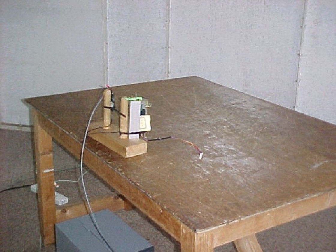
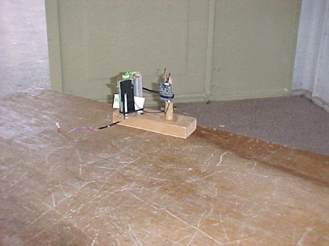
Radio Frequency Investigation Ltd, Ewhurst Park, Ramsdell, Basingstoke, Hampshire, RG26 5RQ, ENGLAND. Tel: +44 (0) 1256 851193 Fax: +44 (0) 1256 851192 Registered in England, No. 211 7901. Registered Office: Ewhurst Park, Ramsdell, Basingstoke, Hampshire RG26 5RQ TESTING 0644 TEST REPORT FROM RADIO FREQUENCY INVESTIGATION LTD. Test Of: i2R Ltd. OEM 400 13.56 MHz Module To: FCC Part 15 Subpart C: 2000 (Intentional Radiators) Section 15.225 Test Report Serial No: RFI/EMCB2/RP43135A Supersedes Test Report Serial No: RFI/EMCB1/RP43135A This Test Report Is Issued Under The Authority Of Richard Jacklin, Operations Director: pp Checked By: pp Tested By:Release Version No: PDF01 Issue Date: 20 March 2002Test Date: 27 February 2002 to 05 March 2002 This report is issued in Adobe Acrobat portable document format (PDF). It is only a valid copy of the report if it is being viewed in PDF format with the following security options not allowed: Changing the document, Selecting text and graphics, Adding or changing notes and form fields. Furthermore, the date of creation must match the issue date stated above. This report may be copied in full. The results in this report apply only to the sample(s) tested. RADIO FREQUENCY INVESTIGATION LTD.TEST REPORT S.No. RFI/EMCB2/RP43135A EMC DepartmentPage 2 of 28 Issue Date: 20 March 2002 Test Of:i2R Ltd. OEM 400 13.56 MHz Module To:FCC Part 15 Subpart C: 2000 (Intentional Radiators) Section 15.209 This page has been left intentionally blank. RADIO FREQUENCY INVESTIGATION LTD.TEST REPORT S.No. RFI/EMCB2/RP43135A EMC DepartmentPage 3 of 28 Issue Date: 20 March 2002 Test Of:i2R Ltd. OEM 400 13.56 MHz Module To:FCC Part 15 Subpart C: 2000 (Intentional Radiators) Section 15.209 Table of Contents 1. Client Information......................................................................................................4 2. Equipment Under Test (EUT).....................................................................................5 3. Test Specification, Methods And Procedures..........................................................7 4. Deviations From The Test Specification...................................................................8 5. Operation Of The EUT During Testing......................................................................9 6. Summary Of Test Results........................................................................................10 7. Measurements, Examinations And Derived Results..............................................11 8. Measurement Uncertainty........................................................................................17 Appendix 1. Test Equipment Used...............................................................................18 Appendix 2. Measurement Methods............................................................................19 Appendix 3. Test Configuration Drawings..................................................................23 Appendix 4. Photographs of EUT.................................................................................28 Test Report Serial No: RFI/MPTB2/RP43135A supersedes Test Report Serial No: RFI/MPTB1/RP43135A RADIO FREQUENCY INVESTIGATION LTD.TEST REPORT S.No. RFI/EMCB2/RP43135A EMC DepartmentPage 4 of 28 Issue Date: 20 March 2002 Test Of:i2R Ltd. OEM 400 13.56 MHz Module To:FCC Part 15 Subpart C: 2000 (Intentional Radiators) Section 15.209 1. Client Information Company Name: i2R Ltd Address: Unit 10 Loughborough Tech Centre Epinal Way Loughborough Leicestershire LE11 3GE Contact Name: Mr R Brown RADIO FREQUENCY INVESTIGATION LTD.TEST REPORT S.No. RFI/EMCB2/RP43135A EMC DepartmentPage 5 of 28 Issue Date: 20 March 2002 Test Of:i2R Ltd. OEM 400 13.56 MHz Module To:FCC Part 15 Subpart C: 2000 (Intentional Radiators) Section 15.209 2. Equipment Under Test (EUT) The client has supplied the following information (with the exception of the Date of Receipt): 2.1. Identification Of Equipment Under Test (EUT) Brand Name: i2R Ltd Model Name or Number: OEM 400 Unique Type Identification: None stated by client Serial Number: X14000295 Country of Manufacture: UK FCC ID Number: Not Stated by Client Date of Receipt: 07 February 2002 2.2. Description Of EUT The EUT is a RFID Tag Reader Module. 2.3. Modifications Incorporated In EUT The EUT has not been modified from the Model Number stated above. RADIO FREQUENCY INVESTIGATION LTD.TEST REPORT S.No. RFI/EMCB2/RP43135A EMC DepartmentPage 6 of 28 Issue Date: 20 March 2002 Test Of:i2R Ltd. OEM 400 13.56 MHz Module To:FCC Part 15 Subpart C: 2000 (Intentional Radiators) Section 15.209 2.4. Support Equipment The following equipment was used to support the EUT during testing. Description: Printer Brand Name: SATO Model Name or Number: CL412e Serial Number: 10170115 FCC ID Number: Not applicable Cable Length And Type: Not Applicable Connected to Port: EUT Connected Internally Description: Extension Lead (Signal/Power) Brand Name: I2R Ltd Model Name or Number: None Stated by Client Serial Number: None Stated by Client FCC ID Number: Not applicable Cable Length And Type: 1m Multicore Shielded Connected to Port: Signal/Power Description: Extension Lead (Antenna) Brand Name: I2R Ltd Model Name or Number: None Stated by Client Serial Number: None Stated by Client FCC ID Number: Not applicable Cable Length And Type: 1m Coaxial Connected to Port: Antenna RADIO FREQUENCY INVESTIGATION LTD.TEST REPORT S.No. RFI/EMCB2/RP43135A EMC DepartmentPage 7 of 28 Issue Date: 20 March 2002 Test Of:i2R Ltd. OEM 400 13.56 MHz Module To:FCC Part 15 Subpart C: 2000 (Intentional Radiators) Section 15.209 3. Test Specification, Methods And Procedures 3.1. Test Specification Reference: FCC Part 15 Subpart C: 2000 (Intentional Radiators). Section 15.225. Title: Code of Federal Regulations, Part 15 (47CFR15) Radio Frequency Devices: Digital Devices. Comments: A description of the test facility used for this test is on file with, and has been accepted by, the Federal Communicati…
Text truncated - open the document above for the full version.
Contact Information
Applicant
Dr. David R Evans(Managing Director)
Technical Contact
i2RGary M Bishop
[email protected]+44 1509 213141
Unit 10, Loughborough Tech. Centre, · Loughborough · United Kingdom
Test Firm
RFI Global Services Ltd.Allan Hume
Technical Specifications
| # | Rule Parts | Frequency Range | Power Output | Tolerance |
|---|---|---|---|---|
| 1 | 15C | 13.56 MHz - 13.56 MHz | 1.00 µW | 0.0100000000 % |
Other Applications from I2R Ltd
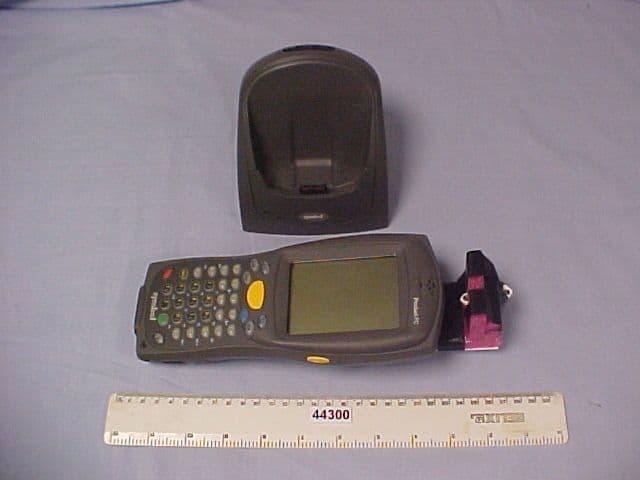
P5ROEM176SAC
Jun 25, 2003RFID Reader and Barcode Scanner Module
Equipment Class
DXT - Part 15 Low Power Transceiver, Rx Verified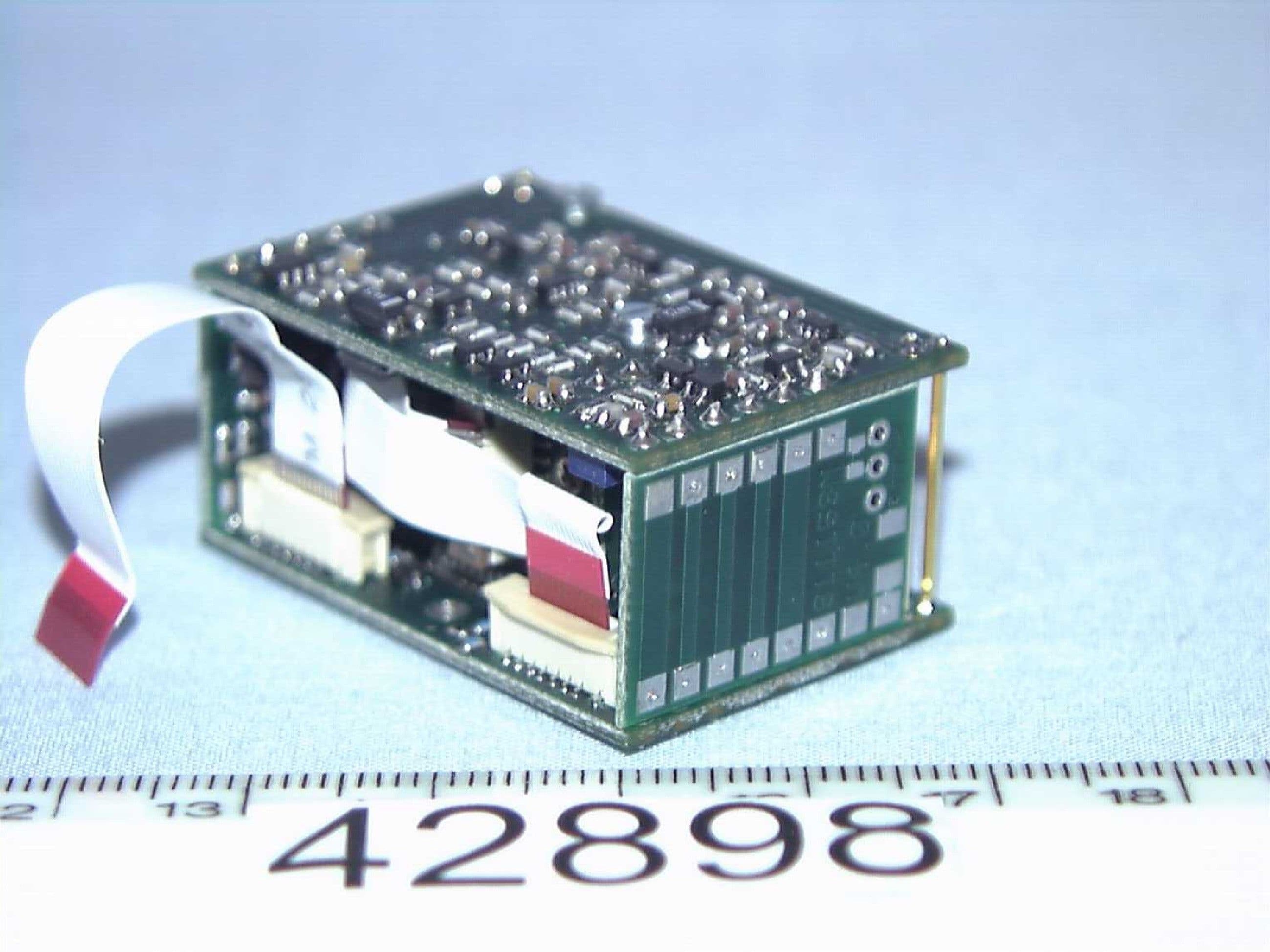
P5ROEM410V12
Apr 22, 2003RFID Reader Module
Equipment Class
DXT - Part 15 Low Power Transceiver, Rx Verified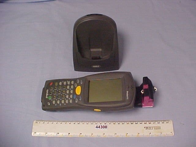
P5ROEM176SAT
Mar 12, 2003RFID Reader and Barcode Scanner Module
Equipment Class
DXT - Part 15 Low Power Transceiver, Rx Verified