P68ADB2381AAA1Wireless Headset
Audex Telecom Industrial Co. Ltd.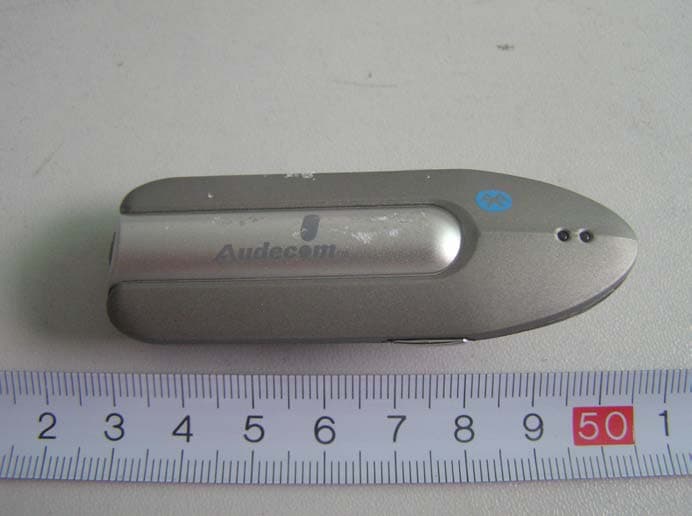
Click to zoom
Application Details
- Equipment Class
- DSS - Part 15 Spread Spectrum Transmitter
- Date of Grant
- May 11, 2006
- Application Purpose
- Original Equipment
- Date of Application
- May 11, 2006
- Equipment Note
- Wireless Headset
- Frequency Range
- 2402.00000000 - 2480.00000000
- Country
- China
Documents & Files
Document Text
Text extracted from the exhibit documents filed with the FCC. Open a document above to read the original.
Users Manual
FREEDOM TO EXPLORE ASCENT For cellphones A A A B 1 a t 8 t e 3 r 2y - B B l u D e A t o o t h H e a d s e t f o r c e l l p h o n e s AAAAAA battery User’s Guide ADB-2381 Made in China Http://www.celleden.com www.celleden.com Introduction 1 Introduction ® The ADB-2381 is a portable handsfree device using advanced Bluetooth ® technology. Using Bluetooth version 1.2, it provides a fast connection speed and excellent sound quality. The ADB-2381 uses one AAA battery which delivers long standby and talking times. The battery is easily replaced and there's no need for recharging. The ADB-2381 supports both the headset and handsfree profiles so it ® can be paired with any other Bluetooth enabled devices with these profiles, such as mobile phones or computers, thus freeing your hands for other tasks. The controls are easy to operate and can be activated with one hand while the headset is in use. Operation Requirement ® The ADB-2381 can connect with any Bluetooth device which supports the headset or handsfree profiles. 2 Contents This package contains the following: 1. Headset 2. One AAA alkaline battery 3. Ear Hook 4. Quick Guide 5. User's Guide The accessories may be subject to change for the sake of product improvement. Changes may be made without prior notice. 4 Operating Instructions: Replacing the battery 1. If the battery runs low in your headset, the bottom (red) LED will flash intermittently, and there will be a slight beep tone from the speaker indicating that the voltage is running low. 2. In such a case, the battery should be replaced. 3. Simply open the battery door at the top of the headset to access the battery compartment. Remove the old battery and replace with a fresh alkaline AAA. 4. Insure that the polarity of the battery matches the markings on the case. 3 Features 1. Talk Button: Controls multiple headset functions 2. Battery door: For accessing and changing the battery 3. Ear Hook: Can be rotated for right or left ear 4. LED indicator: Provides visual cue of headset status 5. Microphone 6. Speaker 7. Volume Up 8. Volume Down 5 Operating Instructions: Note: A fresh headset battery will yield approximately 15 hrs. of talking time and more than two weeks standby. Replacing the battery 6 Operating Instructions: Note: Avoid touching the headset battery cover when in use, which may accidently open the cover door. Changing for wear on the left ear: 0 1) Open the ear hook (90 from the headset); 0 2) Rotate the ear hook by 180; 3) Press the ear hook to the speaker of the headset; 8 Operating Instructions: 7 Operating Instructions: Wearing the headset When packaged, the headset is originally set-up to be worn on the right ear. 1. Open the ear hook approximately 45° away from the unit. 2. Place the ear hook over the ear. 3. Close the headset flat against the ear hook, insuring good auditory reception. 4. Point the microphone towards your mouth. 10 Operating Instructions: 6 seconds 9 Operating Instructions: 2 seconds Turning the headset on: 1. Press and hold the Talk button for about 6 seconds, until the green LED flashes and there is a brief tone from the speaker. 2. The headset is now on and in Standby mode. Note: If the battery is low, the red LED will flash. Turning the headset off: 1. Press and hold the Talk button for approx. 2 seconds. The red LED will flash and there will be a brief tone from the speaker. The unit will then power off. Pairing ® 1) Put the Bluetooth device within 30 cm. of the headset. 2) Make sure the headset is off. Keep pressing the Talk button for about 6 seconds until the red and green LED indicators flash alternately. The earpiece is now in pairing mode. 3) Perform a device discovery from your phone. (For details on device discovery for your phone, refer to the phone's user's guide.) When the scan is complete, the phone displays the devices found. Before you use the headset, you must pair it with your ® mobile phone or other Bluetooth device. “Pairing”creates a ® secure link between Bluetooth devices, and allows the phone or other device to remember the headset's unique ID. When the headset is paired to the mobile phone, it will automatically connect to the mobile phone. Note: 12 Operating Instructions: Answering a call: When the headset rings or the audio signal is heard, press the Talk button briefly. Rejecting a call: To refuse an incoming call, press and hold the Talk button for approximately 2 seconds and the call will be refused. Ending a call: Same as the steps for answering a call. Note: If your mobile phone is Sony Ericsson, please see the table in Section 14 for more information. 11 Operating Instructions: 4) Select the ADB-2381 from the discovered devices list and confirm following the on-screen prompts. 5) When prompted by the phone, enter the password “1234” and confirm the pairing with the phone. Pairing is successful when the red LED stops flashing. The device's ID is now stored in the phone's memory. They can connect automatically when you use them afterward. 13 Operating Instructions: Adjusting the volume: Use the Volume Up or Volume Down buttons to increase or decrease the volume. At each increment, there will be a slight tone from the speaker, until it reaches its maximum or minimum level. Note: It is strongly recommended to adjust the volume slowly and in increments, to avoid damage to sensitive hearing. Operating Instructions: Functions of the buttons Below are the functions of the buttons when the headset is paired with the mobile phone: 14 The voice dial and the reject function needs the support of the mobile phone. Please refer to the mobile phone's user's guide. Working Status Off Standby Pairing Starting voice dial When there is incoming call Press Once No function Voice dial Cancel pairing Cancel voice dial Answer Press & Hold Turn on the power (press and hold for 6 seconds) Enter the pairing mode (press and hold for 8 seconds) Turn off the power (press and hold for 2 seconds) Turn off the power Turn off the power Press Once No f…
Text truncated - open the document above for the full version.
External Photos
EXHIBIT B - EUT EXTERNAL PHOTOGRAPHS EUT – Front View EUT – Rear View
ID Label/Location Info
EXHIBIT A - FCC ID LABELING AND LOCATION Proposed FCC ID Labeling Proposed FCC ID Location Front of EUT / Proposed Label Location FCC ID: P68ADB2381AAA1
Internal Photos
EXHIBIT C - EUT INTERNAL PHOTOGRAPHS EUT – Inside View EUT – PCB (1) View EUT – PCB (2) View EUT – PCB (3) View EUT – PCB (4) View
Operational Description
Hopping Information 1 Hopping Range Hereby we declare that the maximum frequency of this device is: 2402-2480MHz. This is according the Bluetooth Core Specification V1.2 (+ critical errata) for devices which will be operated in the USA. This was checked during the Bluetooth Qualification tests (Test Case: TRM/CA/04-E). Other frequency ranges (e.g. for Spain, France, Japan) which are allowed according the Core Specification are not supported by this device. 2 Hopping Sequence Example of a 79 hopping sequence in data mode: 33,04,21,44,23,42,53,46,55,48,40,59,72,29,76,31,08,73, 07,75,09,45,60,39,58,13,47,11,77,52,35,50,65,54,67,56, 69,62,71,64, 37,25,27,66,57,70,74,61,78,63,10,41,05,43, 15,44,64,68,02,70,06,01,51,03,55,05,03,66,53,49,36,47, 3 Receiver input bandwidth The input bandwidth of the receiver is 1MHz. In every connection one Bluetooth device is the master and the other one is the slave. The master determines the hopping sequence. The slave follows this sequence. Both devices shift between RX and TX time slot according to the clock of the master. Additionally the type of connection is set up at the beginning of the connection. The master adapts its hopping frequency and its TX/RX timing according to the packet type of the connection. Also the slave of the connection will use these settings. Repeating of a packer has no influence on the hopping sequence. The hopping sequence generated by the master of the connection will be followed in any case. That means a repeated packet will not be send on the same frequency, it is send on the next frequency of the hopping sequence.
Operational Description
ADB-2381 Bluetooth Earpiece Operating Elements 1. Power supply: Used 1.5V AAA alkalescence battery 2. Power control: U3,D4,L2,C3,C1,C11,C4,C2,C10,R3,R4,R7 and BAT compose the Power cortrol circuit .Step up the voltage from 1.5V to 1.8V . 3. SW1,R8,C18,D2,R2 and C12 compose the ON/OFF circuit, pushing SW1 can startup the U1. 4. MIC1,C5,R17,Q2,C7,C8 and R11 compose the microphone circuit, can transform the sound signal into electricity signal 5. SPK1,R1,C19 and C20 comose the speaker circuit, can transform the electricity signal into sound signal. 6. D1,D3,R5 and R6 compose the indicator light circuit. 7. C8,C9 and L1 compose the antenna circuit. 8. U1,U4,R1,R14,R15 and R16 compose the Bluetooth module circuit .
Operational Description
Product Name Bluetooth earpiece Product ID ADB-2381 Hardware Version Software Version Chipset CSR’s BC02 Audio Chipset Product category Bluetooth specification Qualification/list date Support Profile Power class Power control Antenna Gain :0~2 dBi Frequency range 2.4GHz to 2.4835GHz Spread Spectrum Modulation GFSK/FHSS Data Rate Interoperability Security RF Output power -3.4 dBm Operation range Audio Specification THD Quality Sensitivity Frequency Response Codec Power Consumption Battery 1.5V alkalescence battery Input Power Play time Dimension Weight Channel quantity 79 Frequence warp 2% FEATURE ◆ 3 function button On/Off, Volume up ,Volume down, ◆ Used one AAA battery ◆ 2 indicator Link (Green), Charging and Battery low (Red).
Schematics
BT_earpiece_AAA_meiou.sch-1 - Sat Jul 23 14:17:16 2005
Test Report
Note: The test report is specially limited to the above company and this particular sample only. It may not be duplicated without prior written consent of Bay Area Compliance Lab Corp. (ShenZhen). This report must not be used by the client to claim product certification, approval, or endorsement by NVLAP, NIST or any agency of the US Government. FCC PART 15.247 EMI MEASUREMENT AND TEST REPORT For Audex Telecom Industrial Co., Ltd. 4/F., Chuangye Center, Kangle Rd., Zhongshan Torch Hi-Tech Industrial Zone, Zhongshan China FCC ID: P68ADB2381AAA1 April 27, 2006 This Report Concerns: Original Report Equipment Type: Wirless headset Test Engineer: Charmi Peng and Sam Lin Report No.: RSZ06041004 Test Date: April 19- 26, 2006 Reviewed By: Chris Zeng Prepared By: Bay Area Compliance Lab Corp. (ShenZhen) 6/F, the 3rd Phase of WanLi Industrial Building, ShiHua Road, FuTian Free Trade Zone, ShenZhen, Guangdong 518038, P.R.China Tel: +86-755-33320018 Fax: +86-755-33320008 Audex Telecom Industrial Co., Ltd. FCC ID: P68ADB2381AAA1 Report # 658615.DOC Page 2 of 36 FCC Part 15.247 Test Report TABLE OF CONTENTS GENERAL INFORMATION.......................................................................................................................................4 PRODUCT DESCRIPTION FOR EQUIPMENT UNDER TEST (EUT) ....................................................................................4 OBJECTIVE...................................................................................................................................................................4 RELATED SUBMITTAL(S)/GRANT(S).............................................................................................................................4 TEST METHODOLOGY..................................................................................................................................................4 TEST FACILITY.............................................................................................................................................................4 SYSTEM TEST CONFIGURATION ..........................................................................................................................5 DESCRIPTION OF TEST CONFIGURATION......................................................................................................................5 EQUIPMENT MODIFICATIONS.......................................................................................................................................5 CONFIGURATION OF TEST SETUP.................................................................................................................................6 BLOCK DIAGRAM OF TEST SETUP................................................................................................................................6 SUMMARY OF TEST RESULTS ...............................................................................................................................7 §15.203 - ANTENNA REQUIREMENT......................................................................................................................8 APPLICABLE STANDARD..............................................................................................................................................8 STANDARD APPLICABLE..............................................................................................................................................8 MEASUREMENT RESULT: .............................................................................................................................................8 §15.205, §15.209, §15.247 - RADIATED EMISSION .................................................................................................9 APPLICABLE STANDARD..............................................................................................................................................9 MEASUREMENT UNCERTAINTY....................................................................................................................................9 EUT SETUP..................................................................................................................................................................9 EMI TEST RECEIVER & SPECTRUM ANALYZER SETUP..............................................................................................10 TEST EQUIPMENT LIST AND DETAILS.........................................................................................................................10 TEST PROCEDURE......................................................................................................................................................10 CORRECTED AMPLITUDE & MARGIN CALCULATION.................................................................................................10 TEST RESULTS SUMMARY..........................................................................................................................................11 TEST DATA................................................................................................................................................................11 §15.247(a)(1)-CHANNEL SEPARATION TEST .....................................................................................................15 APPLICABLE STANDARD............................................................................................................................................15 TEST EQUIPMENT LIST AND DETAILS.........................................................................................................................15 TEST PROCEDURE......................................................................................................................................................15 TEST DATA.........................................................................................................................................................…
Text truncated - open the document above for the full version.
Test Setup Photos
EXHIBIT D - TEST SETUP PHOTOGRAPHS Radiated Emission - Front View (1000-25000 MHz) Radiated Emission - Rear View (1000-25000 MHz)
Contact Information
Applicant
Marion Z.(R&D Manager)
Test Firm
Bay Area Compliance Laboratory Corp. (Shenzhen)John Chan
Technical Specifications
| # | Rule Parts | Frequency Range | Power Output |
|---|---|---|---|
| 1 | 15C | 2.40 GHz - 2.48 GHz | 453.90 µW |
Other Applications from Audex Telecom Industrial Co. Ltd.
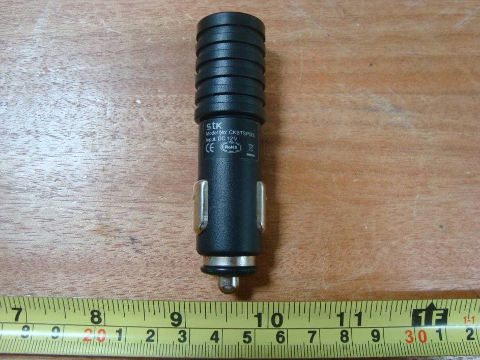
P68MT7000
Mar 24, 2010Motor Trend Bluetooth Headset
Equipment Class
DSS - Part 15 Spread Spectrum TransmitterP68B00788
Dec 21, 2008FM Transmitter
Equipment Class
DXX - Part 15 Low Power Communication Device Transmitter
P68ADB23881898
Jul 23, 2007Bluetooth Micro Headset
Equipment Class
DSS - Part 15 Spread Spectrum Transmitter
P68STB28821818
Dec 21, 2006Bluetooth Wireless Stereo Headphones
Equipment Class
DSS - Part 15 Spread Spectrum Transmitter
P68SPB28022F88
Aug 30, 2006LCD Speakerphone
Equipment Class
DSS - Part 15 Spread Spectrum Transmitter