P6CFSL0512CFL
Foshan Electrical And Lighting Co., Ltd.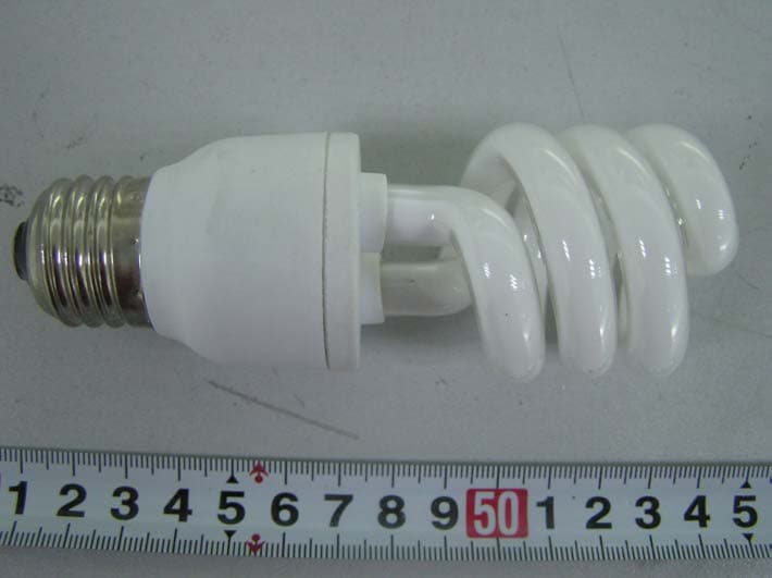
Click to zoom
Application Details
- Equipment Class
- 8CC - Part 18 Consumer Device
- Date of Grant
- Jan 10, 2006
- Application Purpose
- Original Equipment
- Date of Application
- Jan 10, 2006
- Equipment Note
- CFL
- Frequency Range
- 0.04000000 - 0.05000000
- Country
- China
Documents & Files
Document Text
Text extracted from the exhibit documents filed with the FCC. Open a document above to read the original.
Users Manual
FOSHAN ELECTRICAL AND LIGHTING CO . , LTD THE ID CERTIFICATE DOCUMENT NO. Product Depiction Version A/0Pages 3/4 Energy Saving Lamp Introduction Instant start, flicker free Conserves natural resources by at least saving 80% electricity than incandescent bulbs. About 10 times lamp life than a standard incandescent bulb. Notice For Use Never use with the following fixtures: Dimming circuit Emergency lighting fixtures Electronic timer fixtures Direct current fixtures Use only at the rated voltage and frequency circuit. The power voltage must be in the range of 120V±10%. Use indoor only. Never use it where water may drop on the lamp or where the atmosphere is humid. Do not use in enclosed fixture, Or the lamp’s life would be shorten. Always turn off the switch when replacing or cleaning the lamp. Remove and install it by grasping only the plastic portion of the lamp. Added weight may cause instability of free-standing portable lamps in which the distance from the bottom of the base to top of the lamp hold dose not exceed 3 times minimum vase width. Use only with portable lamps which are provided with lamp shade. This product complies with Part 18 of the FCC Rules but may cause interference to Radios, television, wireless telephones, and remote controls. If interference occurs, move product away from the device or plug either into a different outlet. Low EMC or Radio Frequency Interference. The lamp has filter circuits for Cutting out Radio Frequency Interference (RFI) and Complies with Electromagnetic Compatibility (EMC); they give out no harmful Radio Frequency radiation which tends to interfere with Radio, TV, and telecommunication, Mobile phones etc. The lamps are designed to start at very low supply voltages down to about 108VAC and even lower if required, they are also designed to tolerate short term very high supply voltage surges up to 132VAC. These features are most important for developing area where the supply voltage can fluctuate widely. They have short circuit protection ,all plastic materials used are certified Fire Retardant, they can be safely operated in the temperature range of -15 to +65. NOTE This device complies with part 18 of the FCC Rules. 1, Before commissioning this oven please read this instruction manual and keep it carefully. 2, There must be more than 30cm high space necessary above the top surface of oven. 3, Do not repair the oven yourself, please consult an authorized expert. 4, The contents of feeding bottles and bay food jars are to be stirred or shaken and the temperature is to be checked before consumption, in order to avoid burns. 5, Check the oven and the cable regularly for damage. If there is any kind of damage, the oven should not be used. Do not attempt to operate this oven with the door open since open- door operation can result in harmfulexposure to microwave energy. It is important not to defeat or tamper with the safety interlocks. Carefully clean door seala and sealing surfaces. Do not operate the oven if it is damaged. It is particularly important that the oven door close properly and that there is no damage to the : (1) door(bent). (2) hinges and latches( broken or loosened). (3) door seals and sealing surfaces. Utensils sould be checked to ensure that they are suitable for use in microwave ovens. When heating food in plastic or paper containers, check the oven frequently due to the possibility of ignition. Microwave heating of beverages can result in delayed eruptive boiling, therefore care has to be taken when handling the container. If smoke is observed, switch off or unplug the appliance and keep the door closed in order to stifle any flames. Egg in their shell and whole hard- bolled eggs shall not be heated in microwave ovens since they may explode. If the door or door seals are damaged. The oven must not be operated until it has been repaired by a trained person. Liquids or other foods must not be heated in sealed containers since they are liable to explode. Warning: 1, It is hazardous for anyone other than a trained person to carry out any service or repair operation, which involves the removal of any cover which gives protection against exposure to microwave energy. 2, Only allow children to use the oven without supervision when adequate instructions have been given so that the children is able to use the oven in a safe way and understands the hazards of improper use. 3, If the supply cord is damaged, it must be replaced by the manufacture of its service agent or a similarly qualified person in order to avoid a hazard. 4, This product will make disturbance in AV product, if any disturbance is occurred, use different electrical source jack to supply electricity or use low power or away from them. Note: THE MANUFACTURER IS NOT RESPONSIBLE FOR ANY RADIO OR TV INTERFERENCE CAUSED BY UNAUTHORIZATED MODIFICATIONS TO THIS EQUIPMENT .SUCH MODIFICATIONS COULD VOID THE USER’S AUTHORITY TO OPERATE THE EQUIPMENT.
External Photos
External Photos F613 (14) W: EUT-Front View F611W: EUT-Front View F609W: EUT-Front View F607W: EUT-Front View
ID Label/Location Info
ID Label Label FCC ID: P6CFSL0512
ID Label/Location Info
ID Label/Location Label Location Information Specifications: Text is Black or white in color and is left justified. Labels are printed in indelible ink on permanent adhesive backing or silk-screened onto the EUT or shall be affixed at a conspicuous location on the EUT. Label Location F613 (14) W F611WF609W F607W
Internal Photos
Internal Photos F613 (14) W: EUT-Uncovered View F613 (14) W: EUT-PCB Front View F613 (14) W: EUT-PCB Rear View F611W: EUT-Uncovered View F611W: EUT-PCB Front View F611W: EUT-PCB Rear View F609W: EUT-Uncovered View F609W: EUT-PCB Front View F609W: EUT-PCB Rear View F607W: EUT-Uncovered View F607W: EUT-PCB Front View F607W: EUT-PCB Rear View
Operational Description
FOSHAN ELECTRICAL AND LIGHTING CO . , LTD THE ID CERTIFICATE DOCUMENT NO. Circuit Block Diagram and Circuit Description Version A/0Pages 1 1 Circuit Block Diagram 120V 60HZ Input 2 Circuit Description: Fuse: When input is shorted, it performs input shorted protect function. L1C1: Work together with to performs EMI function. D1D2D3D4: Performs rectification function. Q1Q2T: Performs Oscillating function, let low frequency switch high frequency. L2C6: When switching power, the L1 and C6 take place series resonance startup the lamp, then L1 restricting current. Rectification Circuit Filter Circuit Oscillating Circuit Limited DC circuit component Limited circuit component L A M P L N FUSE
Test Report
Note: The test report is specially limited to the above company and this particular sample only. It may not be duplicated without prior written consent of Bay Area Compliance Lab Corp. (ShenZhen). This report must not be used by the client to claim product certification, approval, or endorsement by NVLAP, NIST or any agency of the US Government. FCC PART 18 EMI MEASUREMENT AND TEST REPORT For FOSHAN ELECTRICAL AND LIGHTING CO.,LTD 15North FenJiang Road Foshan Guangdong China FCC ID: P6CFSL0512 January 10, 2006 This Report Concerns: Original Report Equipment Type: CFL Test Engineer: Davis ma Report Number: RSZ05121381 Test Date: November 4, 2005 Reviewed By: Chris Zeng Prepared By: Bay Area Compliance Lab Corp. (ShenZhen) 6/F, the 3rd Phase of WanLi Industrial Building, ShiHua Road, FuTian Free Trade Zone, ShenZhen, Guangdong 518038, P.R.China Tel: +86-755-33320018 Fax: +86-755-33320008 FOSHAN ELECTRICAL AND LIGHTING CO.,LTD FCC ID: P6C FSL0512 Report # RSZ05121381 Page 2 of 18 FCC Part 18 Report TABLE OF CONTENTS GENERAL INFORMATION.......................................................................................................................................3 PRODUCT DESCRIPTION FOR EQUIPMENT UNDER TEST (EUT) ....................................................................................3 O BJECTIVE ...................................................................................................................................................................3 R ELATED S UBMITTAL ( S )/G RANT ( S ).............................................................................................................................3 T EST M ETHODOLOGY ..................................................................................................................................................3 TEST FACILITY.............................................................................................................................................................3 EXTERNAL I/O CABLE.................................................................................................................................................5 SYSTEM TEST CONFIGURATION ..........................................................................................................................6 JUSTIFICATION.............................................................................................................................................................6 EQUIPMENT MODIFICATIONS.......................................................................................................................................6 CONFIGURATION OF TEST SETUP.................................................................................................................................6 BLOCK DIAGRAM OF TEST SETUP................................................................................................................................6 CONDUCTED EMISSION...........................................................................................................................................7 MEASUREMENT UNCERTAINTY....................................................................................................................................7 EUT SETUP..................................................................................................................................................................7 EMI TEST RECEIVER SETUP........................................................................................................................................8 TEST EQUIPMENT LIST AND DETAILS...........................................................................................................................8 TEST PROCEDURE........................................................................................................................................................8 TEST RESULTS SUMMARY............................................................................................................................................8 TEST DATA..................................................................................................................................................................9 P LOT ( S ) OF T EST D ATA ..............................................................................................................................................10 FOSHAN ELECTRICAL AND LIGHTING CO.,LTD FCC ID: P6C FSL0512 Report # RSZ05121381 Page 3 of 18 FCC Part 18 Report GENERAL INFORMATION Product Description for Equipment Under Test (EUT) The FOSHAN ELECTRICAL AND LIGHTING CO.,LTD’s FCC ID: P6C FSL0512, model: F613(14)W, F611W, F609W, F607W or the “EUT” as referred to in this report is a CFL which measures approximately F613 (14) W: 15.0cmL x 4.0cmW x 15.0cmH, F611W: 14.5cmL x 3.5cmW x 14.5cmH F609W: 13.5cmL x 4.0cmW x 13.5cmH, F607W: 13.0cmL x 3.5cmW x 13.0cmH rated input voltage: 120V/60Hz * The test data gathered are from production sample, serial number: 0511108, provided by the manufacturer Objective The following test report is prepared on behalf of FOSHAN ELECTRICAL AND LIGHTING CO.,LTD in accordance with Part 2, Subpart J, and Part 18, Subparts A, B and C of the Federal Communication Commissions rules and regulations. The objective of the manufacturer is to determine compliance with FCC Part 18 limits. Related Submittal(s)/Grant(s) No related submittal(s). Test Methodology All measurements contained in this report were conducted with CISPR 16-1: 2002, radio disturbance and immunity measuring apparatus, and CISPR16-2: 2002, Method of measurement of disturbances and immunity. All radiated and conducted emissions measurement was performed at Bay Area Compliance Lab Corp. (ShenZhen). The radiated testing was performed at an antenna-to-EUT distance of 3 Meters. Test Facility The Test site used by Bay Area Compliance Lab Corp. (ShenZhen) to collect radiated and conducted emission me…
Text truncated - open the document above for the full version.
Test Setup Photos
Test Setup Photos F613 (14) W: Conducted Emission - Front View F613 (14) W: Conducted Emission – Side View F611W: Conducted Emission - Front View F611W: Conducted Emission – Side View F609W: Conducted Emission - Front View F609W: Conducted Emission – Side View F607W: Conducted Emission - Front View F607W: Conducted Emission – Side View
Contact Information
Applicant
Zhuomin Chen(Engineer)
Test Firm
Bay Area Compliance Laboratory Corp. (Shenzhen)John Chan
Technical Specifications
| # | Rule Parts | Frequency Range | Power Output |
|---|---|---|---|
| 1 | 18 | 0.04 MHz - 0.05 MHz | - |
Other Applications from Foshan Electrical And Lighting Co., Ltd.
P6CFSL0702
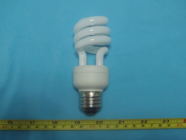
Mar 18, 2007SAVING ENERGY LAMP
Equipment Class
8CC - Part 18 Consumer Device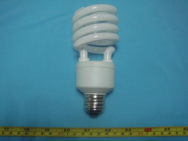
P6CFSL0703
Mar 15, 2007SAVING ENERGY LAMP
Equipment Class
8CC - Part 18 Consumer Device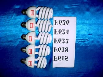
P6CFSLXULI236
Feb 07, 2002Energy Saving Lamp
Equipment Class
8CC - Part 18 Consumer Device