P6CFSL0703SAVING ENERGY LAMP
Foshan Electrical And Lighting Co., Ltd.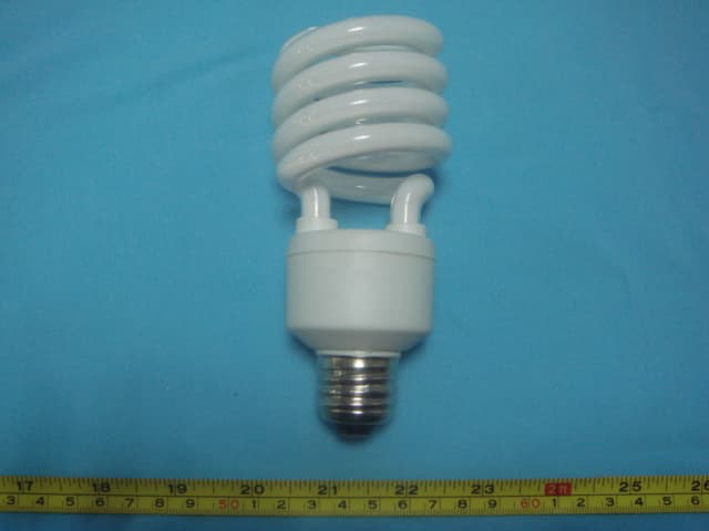
Click to zoom
Application Details
- Equipment Class
- 8CC - Part 18 Consumer Device
- Date of Grant
- Mar 15, 2007
- Application Purpose
- Original Equipment
- Date of Application
- Mar 15, 2007
- Equipment Note
- SAVING ENERGY LAMP
- Frequency Range
- 0.04000000 - 0.05000000
- Country
- China
Documents & Files
Document Text
Text extracted from the exhibit documents filed with the FCC. Open a document above to read the original.
Users Manual
Energy Saving Lamp Introduction ● Instant start, flicker free ● Conserves natural resources by at least saving 80% electricity than incandescent bulbs. ● About 10 times lamp life than a standard incandescent bulb. Notice For Use ● Never use with the following fixtures: Dimming circuit Emergency lighting fixtures Electronic timer fixtures Direct current fixtures ● Use only at the rated voltage and frequency circuit. The power voltage must be in the range of 120V±10%. ● Use indoor only. Never use it where water may drop on the lamp or where the atmosphere is humid. ● Do not use in enclosed fixture, Or the lamp’s life would be shorten. ● Always turn off the switch when replacing or cleaning the lamp. Remove and install it by grasping only the plastic portion of the lamp. ● Added weight may cause instability of free-standing portable lamps in which the distance from the bottom of the base to top of the lamp hold dose not exceed 3 times minimum vase width. Use only with portable lamps which are provided with lamp shade. ● This product complies with Part 18 of the FCC Rules but may cause interference to Radios, television, wireless telephones, and remote controls. If interference occurs, move product away from the device or plug either into a different outlet. ● Low EMC or Radio Frequency Interference. The lamp has filter circuits for Cutting out Radio Frequency Interference (RFI) and Complies with Electromagnetic Compatibility (EMC); they give out no harmful Radio Frequency radiation which tends to interfere with Radio, TV, and telecommunication, Mobile phones etc. ● The lamps are designed to start at very low supply voltages down to about 108VAC and even lower if required, they are also designed to tolerate short term very high supply voltage surges up to 132VAC. These features are most important for developing area where the supply voltage can fluctuate widely. ● They have short circuit protection ,all plastic materials used are certified Fire Retardant, they can be safely operated in the temperature range of -15°C to +65°C. ● This product may cause interference to radio equipment and should not be installed near maritime safety communications equipments or other critical navigation or communication equipment operating between 0.45-30MHz
Block Diagram
Circuit Block Diagram L Limited DC circuit FUSE Rectification Filter Oscillating component L A Circuit Circuit Circuit M Limited circuit N component P 110VAC 60Hz Input FREQ>40kHz
External Photos
EUT
ID Label/Location Info
FCC ID Label Sample for Model: ELS-M24(ELS-M23), ELS-M22, ELS-M20, ELS-M18, ELS-M15 FCC ID: P6CFSL0703
ID Label/Location Info
FCC ID Label The Label must not be a stick-on paper. The Label on these products must be permanently affixed to the product and readily visible at the time of purchase and must last the expected lifetime of the equipment not be readily detachable. Proposed Label Location on EUT EUT Top View/ proposed FCC Mark Location FCC ID:P6CFSL0703
Internal Photos
PCB-Front View for ELS-M15 PCB-Back View for ELS-M15 PCB-Front View for ELS-M18 PCB-Back View for ELS-M18 PCB-Front View for ELS-M20 PCB-Back View for ELS-M20 PCB-Front View for ELS-22 PCB-Back View for ELS-M22 PCB-Front View for ELS-M24(ELS-M23) PCB-Back View for ELS-M24(ELS-M23)
Operational Description
Circuit Description: Fuse: When input is shorted, it performs input shorted protect function. L1,C0: Work together with to performs EMI function. D1,D2,D3,D4: Performs rectification function. Q1, Q2, T: Performs Oscillating function, let low frequency switch high frequency. L2,C5: When switching power, the L1 and C6 take place series resonance startup the lamp, then L1 restricting current.
Schematics
Schematic Diagram
Test Report
FCC TEST REPORT Page 1 of 31 FCC ID : P6CFSL0703 Applicant : Foshan Electrical and Lighting Co., Ltd. 15 North Fenjiang Road, Foshan, Guangdong, P.R.China Equipment Under Test (EUT) : Product description : Energy Saving Lamp Model No. : ELS-M24(ELS-M23), ELS-M22, ELS-M20, ELS-M18, ELS-M15 Standards : FCC Part18 Date of Test : March 14, 2007 Test Engineer : Tiger Su Reviewed By : PERPARED BY: Waltek Services (Shenzhen) Co., Ltd. 8C,West Tower, Aidi Building, No.5003 Binhe Rd, Futian District, Shenzhen518045, Guangdong, China. Tel: 86-755-83551033 Fax: 86-755-83552400 Foshan Electrical and Lighting Co., Ltd. FCC ID: P6CFSL0703 Page 2 of 31 2 Contents Page 1 COVER PAGE..........................................................................................................................................................1 2 CONTENTS ..............................................................................................................................................................2 3 TEST SUMMARY....................................................................................................................................................4 4 GENERAL INFORMATION..................................................................................................................................5 4.1 CLIENT INFORMATION............................................................................................................................................5 4.2 GENERAL DESCRIPTION OF E.U.T...........................................................................................................................5 4.3 DETAILS OF E.U.T. .................................................................................................................................................5 4.4 DESCRIPTION OF SUPPORT UNITS...........................................................................................................................5 4.5 STANDARDS APPLICABLE FOR TESTING..................................................................................................................5 4.6 TEST METHODOLOGY.............................................................................................................................................5 4.7 TEST FACILITY........................................................................................................................................................6 4.8 TEST LOCATION......................................................................................................................................................6 5 EQUIPMENT USED DURING TEST ...................................................................................................................7 6 CONDUCTED EMISSION TEST ..........................................................................................................................8 6.1 TEST EQUIPMENT....................................................................................................................................................8 6.2 TEST PROCEDURE...................................................................................................................................................8 6.3 CONDUCTED TEST SETUP.......................................................................................................................................9 6.4 EUT OPERATING CONDITION.................................................................................................................................9 6.5 CONDUCTED EMISSION LIMITS.............................................................................................................................10 6.6 SPECTRUM ANALYZER..........................................................................................................................................10 6.7 FREQUENCY RANGE OF MEASUREMENTS.............................................................................................................11 6.8 CONDUCTED EMISSION TEST RESULT...................................................................................................................11 6.8.1 Measurement Data .....................................................................................................................................11 6.8.2 Conducted Emissions Test Data.................................................................................................................17 7 PHOTOGRAPHS OF TESTING..........................................................................................................................22 7.1 CONDUCTED EMISSION TEST VIEW FOR ELS-M15 ...............................................................................................22 7.2 CONDUCTED EMISSION TEST VIEW FOR ELS-M18 ...............................................................................................22 7.3 CONDUCTED EMISSION TEST VIEW FOR ELS-M20 ...............................................................................................23 7.4 CONDUCTED EMISSION TEST VIEW FOR ELS-M22 ...............................................................................................23 7.5 CONDUCTED EMISSION TEST VIEW FOR ELS-M24 ...............................................................................................24 8 PHOTOGRAPHS-CONSTRUCTIONAL DETAILS .........................................................................................25 8.1 EUT .....................................................................................................................................................................25 8.2 PCB-FRONT VIEW FOR ELS-M15 ........................................................................................................................26 8.3 PCB-BACK VIEW FOR ELS-M15..........................................................................................................................26 8.4 PCB-FRONT VIEW FOR EL…
Text truncated - open the document above for the full version.
Test Setup Photos
Conducted Emission Test View for ELS-M15 Conducted Emission Test View for ELS-M18 Conducted Emission Test View for ELS-M20 Conducted Emission Test View for ELS-M22
Contact Information
Applicant
Zhuomin Chen(Engineer)
Test Firm
Shenzhen Academy of Metrology & Quality InspectionPeter Lin
Technical Specifications
| # | Rule Parts | Frequency Range | Power Output |
|---|---|---|---|
| 1 | 18 | 0.04 MHz - 0.05 MHz | - |
Other Applications from Foshan Electrical And Lighting Co., Ltd.
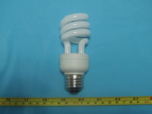
P6CFSL0702
Mar 18, 2007SAVING ENERGY LAMP
Equipment Class
8CC - Part 18 Consumer Device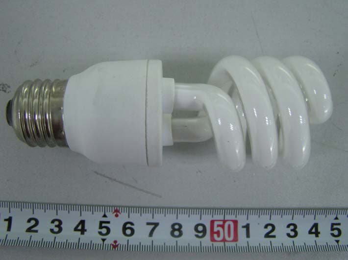
P6CFSL0512
Jan 10, 2006CFL
Equipment Class
8CC - Part 18 Consumer Device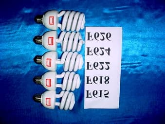
P6CFSLXULI236
Feb 07, 2002Energy Saving Lamp
Equipment Class
8CC - Part 18 Consumer Device