P6JQREX-X150LCD PC
Hyojincontec Co., Ltd.
Click to zoom
Application Details
- Equipment Class
- JBC - Part 15 Class B Computing Device/Personal Computer
- Date of Grant
- Apr 02, 2003
- Application Purpose
- Original Equipment
- Date of Application
- Apr 02, 2003
- Equipment Note
- LCD PC
- Company
- Hyojincontec Co., Ltd.
- Country
- South Korea
Documents & Files
Document Text
Text extracted from the exhibit documents filed with the FCC. Open a document above to read the original.
Users Manual
User’s Manual Qrex-X150 X150 User’s Manual - 2 - Table of Contents 1.SPECIFICATIONS.............................................................................................................................................3 2.IMPORTANT SAFETY INSTRUCTIONS...................................................................................................4 3.HARDWARE OVERVIEW..............................................................................................................................6 3.1.USING THE KEYBOARD / MOUSE.............................................................................................................10 4.INSTALLING DRIVER.................................................................................................................................13 4.1.INSTALLING CHIPSET DRIVER..................................................................................................................13 4.2.INSTALLING LAN DRIVER......................................................................................................................14 4.3.INSTALLING AUDIO DRIVER (WIN98 / ME)...........................................................................................16 4.4.INSTALLING AUDIO DRIVER (WIN2000)................................................................................................17 4.5.INSTALLING VGA DRIVER.....................................................................................................................18 4.6.SETTING TWIN VIEW...............................................................................................................................19 4.7.TOUCH DRIVER.......................................................................................................................................21 4.7.1.Installation.........................................................................................................................................21 4.7.2.How to Use TouchTool.....................................................................................................................22 4.8.INSTALLING TV MODUL.........................................................................................................................26 X150 User’s Manual - 3 - 1. Specifications Processor Intel Pentium 4 processor (1.7 / 1.8 / 2.0 / 2.4 / 2.53GHz up to reserved) System memory 2 Sockets for DDR up to 1GB Display 17” TFT LCD Resolution : 1024 x 768 Color : 16,777,256 (24bit) Pixel pitch : 0.297mm x 0.297mm Luminance : 250cd / m 2 Tilt : -5 ~ 20 degree Viewing angle : Horizontal 140 degree / Vertical 115 degree Graphic High Performance AGP Graphic card Video RAM : 64MB Microsoft DirectX and OpenGL Optimization and support Touch Screen Analog resistive (option) Network Interface Realt 8100 10/100 base-T Ethernet controller, supporting wake on LAN (WOL) Audio AC’97 3D positional PCI audio controller and AC’97 audio codec Speaker Stereo Speaker & Woofer Speaker Bios Award PnP and Flash BIOS Industrial standard WfM 2.0, PCI 2.2, ACPI 1.0, APM 1.2 I/O Interface 4 x Universal serial bus (USB) 1 x Parallel port 2 x Serial port 1 x VGA (External) 1 x TV out 1 x TV-antenna(option with Remote control) 1 x RJ-45 (LAN) port 1 x Line-in jack 1 x Line-out jack 1 x Microphone-in jack 1 x Game port 2 x IEEE 1394 Drive Slim FDD Slim CD-RW (option) Slim CD-ROM Slim DVD-ROM (option) Storage Industry – Standard internal ATA 66/100 HDD (choice of storage capacity) Housing 414.6mm(W) x 478mm(H) x 236mm(D) Weight 13kg Environmental spec Surrounding Temperature : Storage Temperature : 0 ~ 40 degree -20 ~ 60 degree Power Supply 200W micro ATX switching power supply Power Management ACPI compliant OS Installed Microsoft Windows 95, 98, ME, 2000, XP (option) X150 User’s Manual - 4 - 2. Important Safety Instructions The following instructions pertain to the risk of fire, electric shock or bodily injury. Please read all of these instructions carefully. Do not use this computer on an unstable cart. The product may fall, causing serious damage to the product This product should never be placed near or over radiator or heat register Do not place the product in too high or too low temperature Do not place the product in humid Do not hit or drop the product while operating. You may get injury or the product will be damage Do not use banded or twisted or cracked diskette Do not use the product near water Do not spill water, alcohol, Benzol or ant chemical material onto / into product It causes damage or fire Do not open back cover to disassemble, repair or modify by yourself * Please call near service center to repair. Do not disassemble the product while plugged into outlet. It may cause injury, fire or electric shock X150 User’s Manual - 5 - 3. Information to user : PART 15, PARAGRAPH 15.21 AND 15.105(b) Changes or modifications not expressly approved by the party responsible for compliance could void the user’s authority to operate the equipment 4. FCC Notice NOTE : This equipment has been tested and found to comply with the limits for a Class B digital device, pursuant to Part 15 of the FCC Rules. These limits are designed to provide reasonable protection against harmful interference in a residential installation. This equipment generates, uses and can radiate radio frequency energy and, if not installed and used in accordance with the instructions, may cause harmful interference to radio communications. However, there is no guarantee that interference will not occur in a particular installation. If this equipment does cause harmful interference to radio or television reception, which can be determined by turning the equipment off and on, the user is encouraged to try to correct the interference by one or more of the following measures: - Reorient or relocate the receiving antenna. - Increase the separation between the equipment and receiver - Connect the equipment into an outlet on a circuit different from that to w…
Text truncated - open the document above for the full version.
Block Diagram
A A AA FirmWare Hub BROOKDALE-G Processor VR BLOCK DIAGRAM IDE Secondary CK_408 UDMA/100 AGTL+ BUS USB PORT 1-6 USB2.0 IDE Primary 478-PIN P4 PROCESSOR Mini-AGP USB Serial 1 CTRL Game Port PCI CONN 1 Serial 2 DATA Connector Floppy CTRL Parallel Mouse ICH4 DDR266 Keyboard PCI ADDR/DATA GMCH AC'97 LINK PCI CNTRL ADDRDATA Modules SIO ADDR AC'97 CODEC VGA Connector PCI ADDR/DATA PCI CNTRL IEEE 1394 PCI ADDR/DATA PCI CNTRL LAN RTL8100B LCD LTM150XH-L01 BLOCK DIAGRAM 101 BLOCK DIAGRAM 11, 10 30, 2002 QREX-X150 Title SizeDocument NumberRev Date:Sheetof
External Photos
Report No. : 2003KESEMC-II-100.FCC Page : 1 of 17 External Photos l Front View l Rear View
ID Label/Location Info
Report No. : 2003KESEMC-II-100.FCC Page : 1 of 17 Label Location l Label Location l Label
Internal Photos
Report No. : 2003KESEMC-II-100.FCC Internal Photos l Inside View l Top View of I/O Board 1 Report No. : 2003KESEMC-II-100.FCC l Bottom View of I/O Board 1 l Top View of I/O Board 2 Report No. : 2003KESEMC-II-100.FCC l Bottom View of I/O Board 2 l Top View of A/D Board Report No. : 2003KESEMC-II-100.FCC l Bottom View of A/D Board l View of HDD Report No. : 2003KESEMC-II-100.FCC l View of FDD l Top View of LCD Panel Report No. : 2003KESEMC-II-100.FCC l Bottom View of LCD Panel l Top View of Touch Screen Board Report No. : 2003KESEMC-II-100.FCC l Bottom View of Touch Screen Board l Top View of Inverter Report No. : 2003KESEMC-II-100.FCC l Bottom View of Inverter l Top View of AMP Board Report No. : 2003KESEMC-II-100.FCC l Bottom View of AMP Board l Top View of CPU Report No. : 2003KESEMC-II-100.FCC l Bottom View of CPU l Top View of Sound Board Report No. : 2003KESEMC-II-100.FCC l Bottom View of Sound Board l Top View of Video Board Report No. : 2003KESEMC-II-100.FCC l Bottom View of Video Board l Top View of Main Board Report No. : 2003KESEMC-II-100.FCC l Bottom View of Main Board l Power Supply Report No. : 2003KESEMC-II-100.FCC l CD-ROM
Test Report
Report No. : 2003KESEMC-II-100.FCC Page : 2 of 11 Contents 1. General Information 1.1 Manufacturer Information 3 1.2 General Description of EUT 3 1.3 Details of EUT 3 1.4 Description of Support Units 3 1.5 Cable List 4 1.6 System Configuration 4 1.7 Test Set-Up Configuration 5 1.8 Measurement Procedure 5 1.9 Standards Applicable for Testing 5 1.10 Summary of Results 6 2. Radio Disturbance 2.1 Test Results 7 2.2 Frequency Range 7 2.3 Limit Of Conducted And Radiated Emission 7 2.3.1 Limit Of Conducted Emission Of FCC Part 15, Subpart B 7 2.3.2 Limit Of Radiated Emission Of FCC Part 15, Subpart B 7 2.4 Test of Conducted Emission 8 2.4.1 Test Instruments 8 2.4.2 Test Site 8 2.4.3 Operating Environment 8 2.4.4 Measurement Data 8,9 2.5 Test of Radiated Emission 10 2.5.1 Test Instruments 10 2.5.2 Test Site 10 2.5.3 Operating Environment 10 2.5.4 Measurement Data 10,11 Report No. : 2003KESEMC-II-100.FCC Page : 3 of 11 1. General Information 1.1 Manufacturer Information Manufacturer : Hyojin Contec Co., Ltd. Address : Ki-im Bldg 399 Shindorim-Dong, Kuro-Gu, Seoul, Korea 1.2 General Description of EUT Name : LCD PC Model No. : QREX-X150 Serial No : N/A FCC ID : P6JQREX-X150 1.3 Details of EUT Tested Power Supply : AC 110V, 60Hz Port : AC IN, Video, Parallel, Game, Serial, USB, IEEE1394 MIC/Headphone, Line IN, Keyboard, PS/2 Mouse, LAN, Video Out Description of Operating : Display “H” Pattern. Modifications to the EUT : None 1.4 Description of Support Units Product Model No. Serial No. Manufacturer Monitor 950P(T) P029H3NR703017 SAMSUNG Printer BJC-2100SP CME010503120 CANON USB Mouse M-BE58 LZA10709229 Logitech Serial Mouse MSW-5 N/A A-FOUR TECH PS/2 Mouse OK-520 N/A TECH Keyboard SEM-DT35 05068271 SAMSUNG GAME DHA-2000 N/A DA Hun PC Camera MPC-M20 PLUS 00020919 Niztech MIC/Headphone CD-2MVs N/A Hi-Sonic External HDD FW1260 90943203111A VST Technologies Hub Ethernet Hub 8 N/A 3COM TV CT-1413 933432FH801353 SAMSUNG MP3 Play SM-320VH1 N/A PINE TECH Report No. : 2003KESEMC-II-100.FCC Page : 4 of 11 1.5 Cable List Start END Cable Spec Name I/O Port Name I/O Port Lenth Shield EUT AC IN LISN - 1.0 Unshielded Video Monitor - 1.8 Shielded Parallel Printer - 1.8 Shielded Game Game - 2.5 Unshielded Serial Serial Mouse - 1.8 Shielded USB PC Camera - 1.5 Shielded USB USB Mouse - 1.5 Shielded IEEE 1394 External HDD - 1.5 Shielded MIC/Headphone MIC/Headphone - 2.5 Unshielded LINE IN MP3 Player - 1.5 Unshielded Keyboard Keyboard - 1.8 Shielded PS/2 Mouse PS/2 Mouse - 1.8 Shielded LAN Hub - 4.0 Unshielded Video Out TV - 1.8 Unshielded 1.6 System Configuration Description Model Serial No. Manufacturer I/O Board 2 REAR2X N/A N/A I/O Board 1 REAR1X N/A N/A A/D Board NVIDIA INF N/A Hyojin Contec HDD WD400(40G) WMAAT5215957 Western Digital FDD SFD-321X P4YM6032931 SAMSUNG LCD Panel LTM150XH-L01 4F1F02118F SAMSUNG Touch Screen Board N/A N/A SENA Power Supply ENP-2120H 460539268 Enhance Electronics Inverter GH027A N/A GREEN C&C Tech AMP Board X170 N/A N/A CPU Pentium 4(1.6GHz) N/A INTEL CD-ROM SN-124 N/A SAMSUNG Sound Board SIDE N/A N/A Video Board MA-LTC N/A N/A Main Board LPC-845G N/A Hyojin Contec Report No. : 2003KESEMC-II-100.FCC Page : 5 of 11 1.7 Test Set-Up Configuration 1.8 Measurment Procedure Conducted Emission Testing was performed according ANSI C63.4:1192 in a shielded room with peripherals placed on a table, 0.8m high over a metal floor. It was located more than required distance away from the shielded room wall. Radiated Emission Testing was performed according to ANSI C63.4:1992 at the open field test site. The EUT was placed in a 0.8m high table along with the peripherals. The turn table was separated from the antenna distance 10meters. Cables were placed in a position to produce maximum emissions as determined by experimentation, and operation mode was selected for maximum. The frequencies and amplitudes of maximum emission were measured at varying azimuths, antenna heights and antenna polarities. Reported are maximized emission levels. 1.9 Standards Applicable for Testing Table of tests to be carried out under FCC Part 15, Subpart B, CLASS B Test Standards Status FCC Part 15,Subpart B, Class B Applicable Deviation from Standard No Deviation Monitor EUT Printer PC Camera Keyboard PS/2 Mouse Serial Mouse USB Mouse MP3 Player Head Set Game TV Hub External HDD Report No. : 2003KESEMC-II-100.FCC Page : 6 of 11 1.10 Summary of Results The data collected shows that Model QREX-X150 complies with Part 15.109 and 107 of FCC Technical Rules. The highest emission level observed was at 1.31MHz for Q/P mode conducted emission with a margin of 11.2dB and at 1.16MHz for AV mode conducted emission with a margin of 4.2dB and at 1498.52MHz radiated emission with a margin of 4.04dB in RGB Mode. The highest emission level observed was at 0.96MHz & 1.63MHz for Q/P mode conducted emission with a margin of 15.2dB and at 1.22MHz for AV mode conducted emission with a margin of 5.2dB and at 1256.96MHz radiated emission with a margin of 4.45dB in Video Mode. Report No. : 2003KESEMC-II-100.FCC Page : 7 of 11 Radio Disturbance 2.1 Test Results Results Conducted Emission PASS Radiated Emission PASS 2.2 Frequency Range Conducted Emission : 150 kHz - 30 MHz Radiated Emission : 30 MHz - 1000 MHz, Above 1000MHz 2.3 Limits Of Conducted And Radiated Emission 2.3.1 Limit Of Conducted Emission Of FCC Part 15, Subpart B, CISPR22 Class A (dBuV) Class B (dBuV) FREQUENCY (MHz) Quasi - peak Average Quasi - peak Average 0.15 - 0.5 79 66 66 - 56 56 - 46 0.50 - 5.0 73 60 56 46 5.0 - 30.0 73 60 60 50 Note : (1) The lower limit shall apply at the transition frequencies. (2) The limit decreases linearly with the logarithm of the frequency in the range 0.15 to 0.50 MHz. (3) All emanation from a class A/B digital device or system, including any network of conductors and apparatus connected there to, shall not exceed the level of field strengths specified above. 2.3.2 Limit Of Radiated Emission Of FCC Part 15, Subpart B, CISPR22 Class A (at 10m)* Class …
Text truncated - open the document above for the full version.
Test Setup Photos
Report No. : 2003KESEMC-II-100.FCC Photographs of Test l Front View of Conducted Emission l Rear View of Conducted Emission Report No. : 2003KESEMC-II-100.FCC l Front View of Radiated Emission l Rear View of Radiated Emission
Contact Information
Applicant
Hyun Jong Park(Manager)
Test Firm
SGS Korea Co., Ltd.Julia Choi
Technical Specifications
| # | Rule Parts | Frequency Range | Power Output |
|---|---|---|---|
| 1 | 15B | - | - |
Other Applications from Hyojincontec Co., Ltd.

P6JQREX-X170
Jan 15, 2003LCD PC
Equipment Class
JBC - Part 15 Class B Computing Device/Personal Computer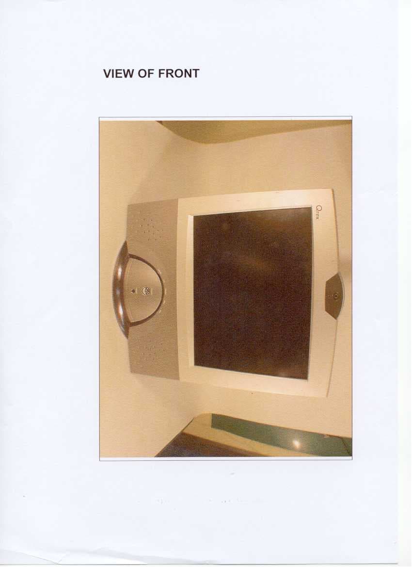
P6JQREX-Q150
Apr 21, 2002LCD PC
Equipment Class
JBC - Part 15 Class B Computing Device/Personal Computer