P6JQREX-X170LCD PC
Hyojincontec Co., Ltd.
Click to zoom
Application Details
- Equipment Class
- JBC - Part 15 Class B Computing Device/Personal Computer
- Date of Grant
- Jan 15, 2003
- Application Purpose
- Original Equipment
- Date of Application
- Jan 15, 2003
- Equipment Note
- LCD PC
- Company
- Hyojincontec Co., Ltd.
- Country
- South Korea
Documents & Files
Document Text
Text extracted from the exhibit documents filed with the FCC. Open a document above to read the original.
Users Manual
User’s Manual Qrex-X170 X170 User’s Manual - 2 - Table of Contents 1.SPECIFICATIONS.............................................................................................................................................3 2.IMPORTANT SAFETY INSTRUCTIONS...................................................................................................4 3.HARDWARE OVERVIEW..............................................................................................................................6 3.1.USING THE KEYBOARD / MOUSE.............................................................................................................10 4.INSTALLING DRIVER.................................................................................................................................13 4.1.INSTALLING CHIPSET DRIVER..................................................................................................................13 4.2.INSTALLING LAN DRIVER......................................................................................................................14 4.3.INSTALLING AUDIO DRIVER (WIN98 / ME)...........................................................................................16 4.4.INSTALLING AUDIO DRIVER (WIN2000)................................................................................................17 4.5.INSTALLING VGA DRIVER.....................................................................................................................18 4.6.SETTING TWIN VIEW...............................................................................................................................19 4.7.TOUCH DRIVER.......................................................................................................................................21 4.7.1.Installation.........................................................................................................................................21 4.7.2.How to Use TouchTool.....................................................................................................................22 4.8.INSTALLING TV MODUL.........................................................................................................................26 X170 User’s Manual - 3 - 1. Specifications Processor Intel Pentium 4 processor (1.4 / 1.5 / 1.6 / 1.7 / 1.8 / 2.0 / 2.2GHz up to reserved) System memory 2 Sockets for DDR up to 1GB Display 17” TFT LCD Resolution : 1280 x 1024 Color : 16,777,256 (24bit) Pixel pitch : 0.26mm x 0.26mm Luminance : 230cd / m 2 Tilt : -5 ~ 25 degree Viewing angle : Horizontal 170 degree / Vertical 170 degree Graphic High Performance AGP Graphic card Video RAM : 32MB Microsoft DirectX and OpenGL Optimization and support Touch Screen Analog resistive (option) Network Interface Intel 10/100 base-T Ethernet controller, supporting wake on LAN (WOL) Audio AC’97 3D positional PCI audio controller and AC’97 audio codec Speaker Stereo Speaker & Woofer Speaker Bios Award PnP and Flash BIOS Industrial standard WfM 2.0, PCI 2.2, ACPI 1.0, APM 1.2 I/O Interface 4 x Universal serial bus (USB) 1 x Parallel port 2 x Serial port 1 x VGA (External) 1 x TV out 1 x TV-antenna(option with Remote control) 1 x RJ-45 (LAN) port 1 x Line-in jack 1 x Line-out jack 1 x Microphone-in jack 1 x Game port 2 x IEEE 1394 Drive Slim FDD Slim CD-RW (option) Slim CD-ROM Slim DVD-ROM (option) Storage Industry – Standard internal ATA 66/100 HDD (choice of storage capacity) Housing 414.6mm(W) x 478mm(H) x 236mm(D) Weight 13kg Environmental spec Surrounding Temperature : Storage Temperature : 0 ~ 40 degree -20 ~ 60 degree Power Supply 200W micro ATX switching power supply Power Management ACPI compliant OS Installed Microsoft Windows 95, 98, ME, 2000, XP (option) X170 User’s Manual - 4 - 2. Important Safety Instructions The following instructions pertain to the risk of fire, electric shock or bodily injury. Please read all of these instructions carefully. Do not use this computer on an unstable cart. The product may fall, causing serious damage to the product This product should never be placed near or over radiator or heat register Do not place the product in too high or too low temperature Do not place the product in humid Do not hit or drop the product while operating. You may get injury or the product will be damage Do not use banded or twisted or cracked diskette Do not use the product near water Do not spill water, alcohol, Benzol or ant chemical material onto / into product It causes damage or fire Do not open back cover to disassemble, repair or modify by yourself * Please call near service center to repair. Do not disassemble the product while plugged into outlet. It may cause injury, fire or electric shock X170 User’s Manual - 5 - 3. Information to user : PART 15, PARAGRAPH 15.21 AND 15.105(b) Changes or modifications not expressly approved by the party responsible for compliance could void the user’s authority to operate the equipment 4. FCC Notice NOTE : This equipment has been tested and found to comply with the limits for a Class B digital device, pursuant to Part 15 of the FCC Rules. These limits are designed to provide reasonable protection against harmful interference in a residential installation. This equipment generates, uses and can radiate radio frequency energy and, if not installed and used in accordance with the instructions, may cause harmful interference to radio communications. However, there is no guarantee that interference will not occur in a particular installation. If this equipment does cause harmful interference to radio or television reception, which can be determined by turning the equipment off and on, the user is encouraged to try to correct the interference by one or more of the following measures: - Reorient or relocate the receiving antenna. - Increase the separation between the equipment and receiver - Connect the equipment into an outlet on a circuit different from that…
Text truncated - open the document above for the full version.
Block Diagram
55 44 33 22 11 D D C C B B A A BLOCK DIAGRAM 4Mx16SDRAM MICRO AGP INTERFACE AGP BUS Silicon lmage Sil164 NVIDIA geforce2 MX200 TMDS TV CRT CONEXANTTV ENCODER BT869 ROM 66MHZ 166MHZ 135MHZ 28MHZ 3.58MHZ 60~85HZ 25~165MHZ LPC-N200 1.0 BLOCK DIAGRAM A 11 Monday, September 23, 2002 TitleSize Document Number Rev Date: Sheet of 5 5 4 4 3 3 2 2 1 1 DD CC BB AA 06 COM_LPT DDR1_2 32 19 05 01 LCD Control MD0_63 31 18 04 MCH-BROOKDALE_B 30 17 IDE 16 MCH-BROOKDALE_C HAREWARE MONITOR MCH-BROOKDALE_A 29 15 POWER_2 WINBOND LPC IO WILLIAMATE_478C 28 14 POWER_1 WILLIAMATE_478B 27 13 DDRPOWER WILLIAMATE_478A 26 12 TITLE PCI1 25 11 03 ICS950202 CLOCK GEN 24 10 SHEET FWH 23 ICH2_1 22 09 MACROMATE M039-LPC845 CODEC ICH2_2 COVER SHEET 21 08 FPANEL BOM & PCB MODIFY HISTORY 20 07 02 USB-P DDR_TERM 33 Pentium 4 478 Pin Intel 845D CHIPS Intel 82801BA CHIPS DDR DIMM DDR DIMM PCI SLOT Micro AGP SLOT 4X Only Winbond W83627HF LPC IO Chip Floppy COM1 RS232COM2 RS232 Printe r Keyboard PS2 Mouse Intel 82562EM IDE1 IDE2 VIA IEE1394 VT6306 IEE1394 Port1 IEE1394 Port2 USB X 4 PortSAC97 Codec CLK IC ICS 950202 VRM 9.0 DC TO DC Converter DDR POWER Control W83301R Micro AGP KB_PS2_GAMEPORT LAN 82562EM Amp 2.2W LM4863 1394 VT6306 1394 PORTS (P31) (P29) (P3,4,5) (P6,7,8) (P12) (P10) (P16) (P32) (P33) (P33) (P17) (P13,14) (P21) (P21) (P25) (P27)(P24) (P18) (P23) (P23) (P23) (P23) (P22)(P22) M039-LPC8450.91 COVER SHEET MACROMATE CORP. Custom 133Tuesday, June 11, 2002 Title SizeDocument NumberRev Date:Sheetof
External Photos
External PHOTOGRAPHS l Front View of Product l Rear View of Product
ID Label/Location Info
Label Location and Label l Label Location l Label
Internal Photos
Internal Photos l Inside View of Product l HDD Test Report No. : 2003KESEMC-II-010.FCC FCC l Top View of Mainboard l Bottom View of Mainboard Test Report No. : 2003KESEMC-II-010.FCC FCC l Top View of VGA Card l Bottom View of VGA Card Test Report No. : 2003KESEMC-II-010.FCC FCC l Top View of Sound Card l Bottom View of Sound Card Test Report No. : 2003KESEMC-II-010.FCC FCC l Top View of CPU l Bottom View of CPU Test Report No. : 2003KESEMC-II-010.FCC FCC l Top View of AMP Board l Bottom View of AMP Board Test Report No. : 2003KESEMC-II-010.FCC FCC l Top View of Inverter l Bottom View of Inverter Test Report No. : 2003KESEMC-II-010.FCC FCC l Top View of Touch Screen Board l Bottom View of Touch Screen Board Test Report No. : 2003KESEMC-II-010.FCC FCC l Top View of LCD Panel l Bottom View of LCD Panel Test Report No. : 2003KESEMC-II-010.FCC FCC l Top View of AD Board l Bottom View of AD Board Test Report No. : 2003KESEMC-II-010.FCC FCC l Top View of I/O 1 Board l Bottom View of I/O 2 Board Test Report No. : 2003KESEMC-II-010.FCC FCC l Top View of I/O 2 Board l Bottom View of I/O 2 Board Test Report No. : 2003KESEMC-II-010.FCC FCC l CD-ROM l Power Supply Test Report No. : 2003KESEMC-II-010.FCC FCC l FDD
Test Setup Photos
PHOTOGRAPHS of TEST SET-UP l Conducted Test Picture Test Report No. : 2003KESEMC-II-010.FCC FCC l Radiated Test Picture
Contact Information
Applicant
Hyun Jong Park(Manager)
Test Firm
SGS Korea Co., Ltd.Julia Choi
Technical Specifications
| # | Rule Parts | Frequency Range | Power Output |
|---|---|---|---|
| 1 | 15B | - | - |
Other Applications from Hyojincontec Co., Ltd.

P6JQREX-X150
Apr 02, 2003LCD PC
Equipment Class
JBC - Part 15 Class B Computing Device/Personal Computer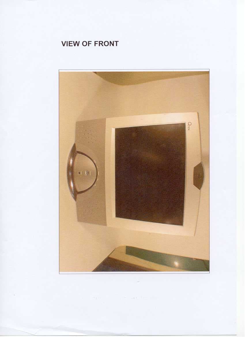
P6JQREX-Q150
Apr 21, 2002LCD PC
Equipment Class
JBC - Part 15 Class B Computing Device/Personal Computer