P8D-C6088IDual Band PCS/GSM Flip-Phone
Mobicom Corporation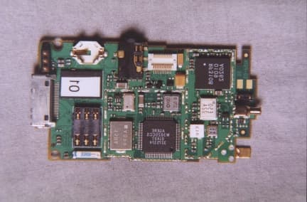
Click to zoom
Application Details
- Equipment Class
- PCE - PCS Licensed Transmitter held to ear
- Date of Grant
- May 07, 2002
- Application Purpose
- Original Equipment
- Date of Application
- Mar 27, 2002
- Equipment Note
- Dual Band PCS/GSM Flip-Phone
- Frequency Range
- 1850.20000000 - 1909.80000000
- Company
- Mobicom Corporation
- Country
- United States
Documents & Files
Document Text
Text extracted from the exhibit documents filed with the FCC. Open a document above to read the original.
Users Manual
introducing C6 series User Menu 2 Getting to know your new phone ongratulations on the purchase of your new Mobicom phone! Your Mobicom phone is an advanced communications device with many features and functions. Please take a moment to familiarize yourself with the capabilities and options of your Mobicom phone. Your familiarity with the operation of your Mobicom phone will help you enjoy it in a safe and productive manner 3 Display Icons Audio Settings Battery level and charge Call Divert Activated Divert Incoming call and on-call indicator Keypad locked Memo or alarm set Messages Phone book Phone number saved in phone Phone number saved in SIM card Secretary Settings Signal strength indicator 4 5 S a f e u s e o f y o u r n e w p h o n e Safe use of your new phone Please observe the following guildlines for safe and respon- sible opperation of your cellular phone Follow all guidelines for safe and legal use of your phone. See detailed information in this manual. Use caution while placing or receiving calls while driving. You should try to find a safe place to pull over and stop driving before placing or receiving a phone call while driving. The use of a hands free headset is required for cell phone use while driving in some areas. Keep your phone switched off near blasting areas where explosives are being detonated. Always observe local rules and regulations that may restrict or prohibit phone use in some areas. When in hospitals or near medical equip- ment local rules and regulations may require that your phone be switched off. FCC regulations require that your phone be switched off while on airplanes. Wireless phones could cause interference with the airplanes equip- ment or air traffic control signals. Keep your phone switched off while refueling. Do not use your phone while near fuel or flammable chemicals. Avoid contact with your phones antenna while the phone is in use. All wireless phones, including this one may receive interference from other sources, which may affect the phones performance. 6 S a f e u s e o f y o u r n e w p h o n e Table of contents Getting to know your new phone 2 Display Icons 3 Safe use of your new phone 5 Table of contents 6 Key Featuresof the Mobicom C6088 & C6288 Phone 11 Getting Started 13 UnPacking 14 Contents 14 Your new phone’s box should con- tain the following items: 14 Installing your SIM Card 14 Charging your phone’s battery 15 Connecting a hands free headset adapter to your phone 16 Using your Phone 17 Turn phone on 17 Welcome Screen 17 Menu: 17 Navigation Keys: 17 Menu Tree 19 Messaging Management- Stay Con- nected with Mobicom 19 Phone Book Management 20 Audio Settings 21 Diverting your Calls 22 7 S a f e u s e o f y o u r n e w p h o n e Settings 23 Secretary 25 Making and Recieving Phone Calls 27 Dial By Number 27 Dial By Name 27 Receive Calls 28 Flip Open Answer: 28 Any Key Answer 28 Audio Settings 29 Audio Settings 29 Setting volume 29 Setting Speach Volume 29 Setting Ringer Volume 29 Setting Tone Volume 30 Settinging a Ringer Type 30 Setting Tone Types 31 Setting Key Tones 31 Setting Info Tones: 31 Setting the SMS Rx. Tone 31 Setting the Serve Tone: 31 Setting One Min Beep Tone 32 View Missed, Received and Placed Calls 33 Viewing Missed Calls 33 Viewing Missed Call details: 33 Copying Missed calls to Phone Book: 34 Editing Missed Calls: 34 34 Deleting Missed Calls: 34 There are several ways to delete the details regarding a Missed call from your phone’s memory: 34 Viewing Received Calls 35 Viewing Received Call details: 35 Copying Received calls to Phone 8 S a f e u s e o f y o u r n e w p h o n e Book: 35 Editing Received Calls: 35 Deleting Received Calls: 36 Viewing Placed Calls 36 Viewing Placed Call details: 36 Copying Placed calls to Phone Book: 37 Editing Placed Calls: 37 Deleting PlacedCalls: 37 Voice Mail 39 Managing Voice Mail: 39 Short Messaging Service ( SMS ) 41 Reading Messages: 41 Reading messages in your INBOX 41 Reading Messages in your Outbox 42 Composing Messages 42 Deleting Messages 43 Delete ALL messages 44 Deleting Messages in your Outbox: 44 Delete a particular Message 44 Delete ALL messages 45 Checking available message memo- ry space 45 Message Set-Up 45 Message Display: 45 Message: 45 Message deliverability 46 Message Status 46 Broadcast: 46 Phone Book 47 Searching by name: 47 Creating an entry in the phone book: 9 S a f e u s e o f y o u r n e w p h o n e 47 Deleting an entry in the phone book: 48 Copying a Phone book entry from the SIM card to the phone: 48 Viewing SIM card and Phone phone books: 48 Checking available phone book memory space: 48 Entering your phone's number into phone book: 49 One-Touch Dialing: 49 Changing Phone Settings 51 Call Settings 51 Flip Open Answer: 51 1 Touch Dial 51 Auto Redial 52 Any Key Answer 52 Call waiting: 52 Clock Setup 53 To Set The Time 53 Seting The Date 53 Setting Time Format 53 Setting Time Zone: 53 Setting Daylight Savings: 53 Screen Setting 54 Setting the Backlight 54 Setting the Contrast 54 Language Settings 55 Setting the Language: 55 Setting the Greeting on your phone 55 Setting the default phone 55 Setting the Security features on your phone: 55 Setting the Network details on your phone: 55 10 S a f e u s e o f y o u r n e w p h o n e Secretary Mode 57 Entering A Memo 57 Setting an Alarm 57 Setting Area Code Search 58 Using the Calculator Utility 58 Using the Global Time Clock 58 Diverting Messages 59 Diverting all calls: 59 Diverting calls when phone is in use: 60 Diverting calls when there is no re- ply: 60 Diverting calls when phone is off: 60 Status of diverting calls: 61 Cancel diverting calls: 61 Troubleshooting 63 Care and maintenance of your new phone 65 Batteries care and maintenance 67 Warranty 69 11 K e y F e a t u r e s o f t h e M o b i c o m C 6 0 8 8 & Key Featuresof the Mobicom C6088 & C6288 Phone Your feature-packed MobiCom phone is the world's small- est, lightest cellular phone. Size L x W x H (mm) C6088 68 x 38 x 20 C6288 68 x 38 x 24 WeightC6…
Text truncated - open the document above for the full version.
Cover Letter(s)
April 29, 2002 attn: TCB Services, Reviewing Engineer MET Laboratories, INC RE: CONFIDENTIALITY REQUEST FOR THE C6088i FCC ID: P8D-C6088I To Whom It May Concern: This letter serves as an official request for confidentiality under FCC Rule Section 0.459. Mobicom Corporation requests that the schematic diagrams, layouts, block diagrams, functional descriptions, parts lists, and calibration procedures required to be submitted with this application be withheld from public review. These documents are company proprietary information that should not get into the possession of competitors. Please contact me if there is any information you may need. Sincerely, Joe Murphy Senior Testing Engineer Mobicom Corporation
External Photos
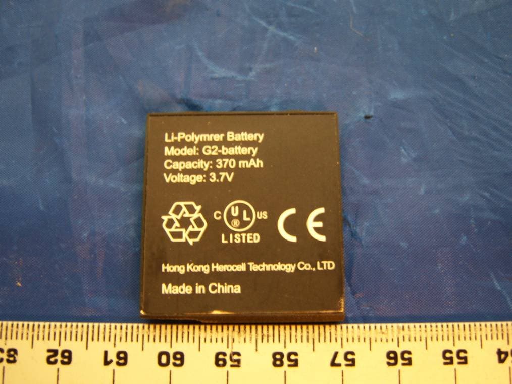
FCC ID: P8D-C6088I FCC ID: P8D-C6088I FCC ID: P8D-C6088I
Internal Photos
FCC ID: P8D-C6088I FCC ID: P8D-C6088I FCC ID: P8D-C6088I
Internal Photos
Mobicom Corporation 960 Holmdel Road Holmdel, NJ 07733 Phone (732) 772-2200 April 29, 2002 Mr. Chris Harvey TCB Services MET Laboratories, Inc. 914 W Patapsco Avenue Baltimore, MD 21230 RE: FCC ID P8D-C6088I, request for additional information Dear Mr. Harvey, I am supplying additional information requested by the FCC for the Mobicom C6088i mobile telephone. This letter addresses the request for: “ Additional photographs. Please take external side photos. Please provide internal photos of the chassis and any other missing parts.” This is item number 5 under the EMC section of Correspondence Reference Number 3904. Please let me know immediately, if the attached data does not satisfy the request. Best Regards, Joe Murphy Senior Test Engineer [email protected] phone: 732-772-2215 fax: 732-834-9806 FCC ID: P8D-C6088I FCC ID: P8D-C6088I FCC ID: P8D-C6088I
Operational Description
2. Testobject Data Type Designation: Kind of Device: (optional) Voltage Type: Voltage level: Equipment under Test: C6088i GSM 900 / PCS1900 Dual Band Mobile Phone DC 3,6 Ports 2.1 General EUT Description General product description: The Equipment Under Test (EUT) is an E-GSM 900 / PCS 1900 dual band mobile phone. In the PCS1900 mode the C6088i operates in blocks A through F from 1850,2 MHz (lowest channel = 512) to 1909,8 MHz (highest channel = 810). The EUT provides the following ports: headset connector bottom connector antenna connector Enclosure The main components of EUT are listed and described in Chapter 3.2 Page 6 of 31 Testreport Reference: 4_Mobi_0201_GSM_FCCb
RF Exposure Info
TTI-P-G 158 Calibration Data for DASY Test-Report, 7-Layers_ 6575_244_C6088i Page 1 of 25 Calibration Data for the Report Dosimetric Assessment of the Mobicom C6088i (FCC ID: P8D-C6088I) According to the FCC Requirements March 06, 2002 IMST GmbH Carl-Friedrich-Gauß-Str. 2 D-47475 Kamp-Lintfort Customer 7 Layers AG Borsigstrasse 11 D-40880-Ratingen This report shall not be reproduced except in full without the written approval of the testing laboratory. calibration_data_fcc_supplement_c _2.1.doc/22.02.2002/CH Calibration Data for DASY Test-Report, 7-Layers_ 6575_244_C6088i Page 2 of 25 calibration_data_fcc_supplement_c _2.1.doc/22.02.2002/CH Calibration Data for DASY Test-Report, 7-Layers_ 6575_244_C6088i Page 3 of 25 calibration_data_fcc_supplement_c _2.1.doc/22.02.2002/CH Calibration Data for DASY Test-Report, 7-Layers_ 6575_244_C6088i Page 4 of 25 calibration_data_fcc_supplement_c _2.1.doc/22.02.2002/CH Calibration Data for DASY Test-Report, 7-Layers_ 6575_244_C6088i Page 5 of 25 calibration_data_fcc_supplement_c _2.1.doc/22.02.2002/CH Calibration Data for DASY Test-Report, 7-Layers_ 6575_244_C6088i Page 6 of 25 calibration_data_fcc_supplement_c _2.1.doc/22.02.2002/CH Calibration Data for DASY Test-Report, 7-Layers_ 6575_244_C6088i Page 7 of 25 calibration_data_fcc_supplement_c _2.1.doc/22.02.2002/CH Calibration Data for DASY Test-Report, 7-Layers_ 6575_244_C6088i Page 8 of 25 calibration_data_fcc_supplement_c _2.1.doc/22.02.2002/CH Calibration Data for DASY Test-Report, 7-Layers_ 6575_244_C6088i Page 9 of 25 calibration_data_fcc_supplement_c _2.1.doc/22.02.2002/CH Calibration Data for DASY Test-Report, 7-Layers_ 6575_244_C6088i Page 10 of 25 calibration_data_fcc_supplement_c _2.1.doc/22.02.2002/CH Calibration Data for DASY Test-Report, 7-Layers_ 6575_244_C6088i Page 11 of 25 calibration_data_fcc_supplement_c _2.1.doc/22.02.2002/CH Calibration Data for DASY Test-Report, 7-Layers_ 6575_244_C6088i Page 12 of 25 calibration_data_fcc_supplement_c _2.1.doc/22.02.2002/CH Calibration Data for DASY Test-Report, 7-Layers_ 6575_244_C6088i Page 13 of 25 calibration_data_fcc_supplement_c _2.1.doc/22.02.2002/CH Calibration Data for DASY Test-Report, 7-Layers_ 6575_244_C6088i Page 14 of 25 calibration_data_fcc_supplement_c _2.1.doc/22.02.2002/CH Calibration Data for DASY Test-Report, 7-Layers_ 6575_244_C6088i Page 15 of 25 calibration_data_fcc_supplement_c _2.1.doc/22.02.2002/CH Calibration Data for DASY Test-Report, 7-Layers_ 6575_244_C6088i Page 16 of 25 calibration_data_fcc_supplement_c _2.1.doc/22.02.2002/CH Calibration Data for DASY Test-Report, 7-Layers_ 6575_244_C6088i Page 17 of 25 calibration_data_fcc_supplement_c _2.1.doc/22.02.2002/CH Calibration Data for DASY Test-Report, 7-Layers_ 6575_244_C6088i Page 18 of 25 calibration_data_fcc_supplement_c _2.1.doc/22.02.2002/CH Calibration Data for DASY Test-Report, 7-Layers_ 6575_244_C6088i Page 19 of 25 calibration_data_fcc_supplement_c _2.1.doc/22.02.2002/CH Calibration Data for DASY Test-Report, 7-Layers_ 6575_244_C6088i Page 20 of 25 calibration_data_fcc_supplement_c _2.1.doc/22.02.2002/CH Calibration Data for DASY Test-Report, 7-Layers_ 6575_244_C6088i Page 21 of 25 calibration_data_fcc_supplement_c _2.1.doc/22.02.2002/CH Calibration Data for DASY Test-Report, 7-Layers_ 6575_244_C6088i Page 22 of 25 calibration_data_fcc_supplement_c _2.1.doc/22.02.2002/CH Calibration Data for DASY Test-Report, 7-Layers_ 6575_244_C6088i Page 23 of 25 calibration_data_fcc_supplement_c _2.1.doc/22.02.2002/CH Calibration Data for DASY Test-Report, 7-Layers_ 6575_244_C6088i Page 24 of 25 calibration_data_fcc_supplement_c _2.1.doc/22.02.2002/CH Calibration Data for DASY Test-Report, 7-Layers_ 6575_244_C6088i Page 25 of 25 calibration_data_fcc_supplement_c _2.1.doc/22.02.2002/CH
RF Exposure Info
TTI-P-G 158 DASY Test-Report, 7-Layers_ 6575_224c Page 1 of 32 Report Dosimetric Assessment of the Mobicom C6088i (FCC ID: P8D-C6088I) According to the FCC Requirements March 06, 2002 IMST GmbH Carl-Friedrich-Gauß-Str. 2 D-47475 Kamp-Lintfort Customer 7-Layers AG Borsigstrasse 11 40880-Ratingen The test results only relate to the items tested. This report shall not be reproduced except in full without the written approval of the testing laboratory. dasy_report_fcc_supplement_c _2.1.doc/25.02.2002/CH DASY Test-Report, 7-Layers_ 6575_224c Page 2 of 32 dasy_report_fcc_supplement_c _2.1.doc/25.02.2002/CH Executive Summary The C6088i is a new mobile phone from Mobicom operating in the 900 MHz and 1900 MHz frequency range. The device has a helix antenna. The system concepts used are the GSM 900 and PCS 1900 standards. The objective of the measurements done by IMST was the dosimetric assessment of one device in the PCS 1900 standard with different batteries. The examinations have been carried out with the dosimetric assessment system „DASY3“. The measurements were made according to the Supplement C to OET Bulletin 65 of the Federal Communications Commission (FCC) Guidelines [FCC 2001] for evaluating compliance of mobile and portable devices with FCC limits for human exposure (general population) to radiofrequency emissions. The Mobicom C6088i mobile phone (FCC ID: P8D-C6088I) is in compliance with the Federal Communications Commission (FCC) Guidelines [FCC 2001] for uncontrolled exposure. The phone was tested with the following batteries: “slim battery” and “extended battery”. In the body worn configuration additionally with: “belt clip” and “headset CH002”. prepared by: ........................................... reviewed by: .............................................. André van den Bosch Dipl.-Ing. Christoph Hennes test engineer quality assurance engineer IMST GmbH Carl-Friedrich-Gauß-Straße 2 D-47475 Kamp-Lintfort Tel. +49- 2842-981 373 Fax +49- 2842-981 399 email: [email protected] DASY Test-Report, 7-Layers_ 6575_224c Page 3 of 32 dasy_report_fcc_supplement_c _2.1.doc/25.02.2002/CH Table of Contents 1 SUBJECT OF INVESTIGATION ................................................................................................................... 4 2 THE IEEE STANDARD C95.1 AND THE FCC EXPOSURE CRITERIA................................................. 4 2.1 DISTINCTION BETWEEN EXPOSED POPULATION, DURATION OF EXPOSURE AND FREQUENCIES...................... 4 2.2 DISTINCTION BETWEEN MAXIMUM PERMISSIBLE EXPOSURE AND SAR LIMITS................................................ 5 2.3 SAR LIMIT................................................................................................................................................... 5 3 THE FCC MEASUREMENT PROCEDURE ................................................................................................ 6 3.1 GENERAL REQUIREMENTS............................................................................................................................ 6 3.2 DEVICE OPERATING NEXT TO A PERSON’S EAR............................................................................................. 6 3.3 BODY-WORN AND OTHER CONFIGURATIONS................................................................................................. 9 4 THE MEASUREMENT SYSTEM ................................................................................................................ 10 4.1 MEASUREMENT PROCEDURE...................................................................................................................... 11 4.2 UNCERTAINTY ASSESSMENT........................................................................................................................ 12 5 SAR RESULTS ................................................................................................................................................ 13 6 EVALUATION ................................................................................................................................................ 15 7 APPENDIX ...................................................................................................................................................... 17 7.1 ADMINISTRATIVE DATA...............................................................................................................................17 7.2 DEVICE UNDER TEST AND TEST CONDITIONS.............................................................................................. 17 7.3 TISSUE RECIPES......................................................................................................................................... 17 7.4 MATERIAL PARAMETERS............................................................................................................................. 18 7.5 SIMPLIFIED PERFORMANCE CHECKING...................................................................................................... 18 7.6 ENVIRONMENT........................................................................................................................................... 21 7.7 TEST EQUIPMENT....................................................................................................................................... 21 7.8 PICTURES OF THE DEVICE UNDER TEST....................................................................................................... 22 7.9 TEST POSITIONS FOR THE DEVICE UNDER TEST........................................................................................... 25 7.10 PICTURES TO DEMONSTRATE THE REQUIRED LIQUID DEPTH........................................................................ 31 8 REFERENCES ................................................................................................................................................ 32 DASY Test-Report, 7-Layers_ 6575_224c Page 4 of 32 dasy_report_fcc_supplement_c _2.1.doc/25.02.2002/CH 1 Subj…
Text truncated - open the document above for the full version.
RF Exposure Info
Mobicom Corporation 960 Holmdel Road Holmdel, NJ 07733 Phone (732) 772-2200 March 29, 2002 - 1 - Mr. Chris Harvey MET Laboratories, Inc. 914 West Patapsco Avenue Baltimore, MD 21230 Subject: FCCID: P8D-C6088I, Transmit Power Calibration Procedures for the C6088i Dear Mr. Harvey, The purpose of this letter is to explain why the highest conducted power listed in the EMC report (29.4dBm) is higher than the value in the SAR report (28.2dBm). This letter will also address how Mobicom will guarantee that our production models will never exceed the FCC limit of 1.6W/kg for SAR measurements. Firstly let me explain the reason for the output power variation between the units tested for Part 24 and SAR. These two models are lab prototypes and as such they were calibrated at our R&D facility in New Jersey. The target power was set to 29.0dBm and an acceptable tolerance of ±1dB was applied to these units. The high tolerance is due to the fact that at the R&D facility we do not have a dedicated calibration setup. These units were calibrated on available test setups and cable loss was estimated rather than calculated. This is acceptable for prototype models, but this is not acceptable for production models. We will not see such transmit power variations with our production calibration setup. In production we use a fixed setup that is calibrated for cable loss and power accuracy, at the start of every 8-hour shift. Every mobile will run through the production calibration program, which uses an Agilent 8960 Series 10 Mobile Phone Manufacturing Test Set for power measurements. This test set has a measurement accuracy of <±0.4dB. Transmit power is adjusted to a set target that is controlled by production software. The target is accurate to <+0.1dB. Based on our manufacturing experience and test equipment specifications, we can reliably set the power of all mobiles to ±0.5dB (equipment accuracy + target accuracy) of our selected target output power. Mobicom Corporation 960 Holmdel Road Holmdel, NJ 07733 Phone (732) 772-2200 March 29, 2002 - 2 - Our SAR report from IMST shows a worst-case measurement of 1.18W/kg. This measurement was recorded with an output power of 28.2dBm. Based on this measurement IMST calculates that we have margin up to 29.5dBm. This means that as long as our output power is below 29.5dBm, our SAR will be below 1.6W/kg. Using these calculations, Mobicom has decided to set the C6088i transmit output power target to 28.5dBm. Applying the ±0.5dB accuracy of our production calibration setup to the 28.5dBm target will generate a highest possible transmit power of 29.0dBm and this is well below the calculated limit of 29.5dBm for SAR compliance. Please feel free to contact me directly with any further questions about our production calibration programs, procedures and equipment. Sincerely, Joseph Murphy Senior Test Engineer [email protected] phone: 732-772-2215 fax: 732-834-9806
RF Exposure Info
Chris Harvey From:Chris Harvey Sent:Saturday, March 16, 2002 4:17 PM To:'[email protected]' Cc:Marianne Bosley; Chris Harvey Subject:C6088I questions Joe, I have had a chance to preliminarily review the 3 SAR reports. I have a concern that the highest RF conducted Power listed in the EMC report is 29.4dBm, where the SAR report has a lower value of 28.2dBm (which is 1.2 dB difference). If the SAR report had higher values than the EMC report, there would be no issue. I did not see a tolerance listed in the documentation provided. What is the Tune-up/tolerance? I have not found any FCC compliance statements regarding either SAR/RF Exposure or typical FCC compliance information located in the Users Manual provided. Have I missed it or have you yet to include this required information to be provided to the users? Upon completion of the complete application review there will be a note on the grant. The note will read something like this (there may be more added upon further review): Highest reported SAR levels are: Head 1.18 W/kg, body 0.244 W/kg. SAR compliance for body-worn operating configurations is limited to the specific belt- clips/holsters/accessories tested for this filing. SAR compliance is limited to the 2 batteries tested for this filing. End-users must be informed of the body-worn operating requirements for satisfying RF exposure compliance. Power is EIRP. Please let us know if you have any questions regarding this request for information (please remember that I will be on travel so my access to e-mails will be limited, so copy [email protected])
RF Exposure Info
TTI-P-G 158 DASY Test-Report, 7-Layers_ 6575_224_SAR Distribution Plots Page 1 of Appendix for the Repor Dosimetric Assessment of Mobicom C6088i (FCC ID: P8D-C6088 I According to the FCC Requiremen SAR Distribution Plo t March 06, 2002 IMST GmbH Carl-Friedrich-Gauß-Str. 2 D-47475 Kamp-Lintfort Customer 7-Layers AG Borsigstrasse 11 40880-Ratingen The test results only relate to the ite This report shall not be reproduced except in full without the wr approval of the testing labora t dasy_report_fcc_supplement_c 2.1_SAR-Plots.doc/22.02.2002/CH p, y___g dasy_report_fcc_supplement_c 2.1_SA R-Plots.doc/22.02.2002/CH Table of Contents 1 SAR DISTRIBUTION PLOTS, TEST SIDE AMBIENT CONDITIONS............................... 2 SAR DISTRIBUTION PLOTS, PCS 1900.......................................................... 5 3 SAR Z-AXIS SCAN........................................................................................... p, y___g dasy_report_fcc_supplement_c 2.1_SA R-Plots.doc/22.02.2002/CH 1 SAR Distribution Plots, Test side ambient conditions. Fig. 1: Test side ambient measurements, 1900 MHz, head position. p, y___g dasy_report_fcc_supplement_c 2.1_SA R-Plots.doc/22.02.2002/CH Fig. 2: Test side ambient measurements, 1900 MHz, body worn position. p, y___g dasy_report_fcc_supplement_c 2.1_SA R-Plots.doc/22.02.2002/CH 2 SAR Distribution Plots, PCS 1900 Fig. 3: SAR distribution, PCS 1900, channel 661, cheek position, left side of head, sli m p, y___g dasy_report_fcc_supplement_c 2.1_SA R-Plots.doc/22.02.2002/CH Fig. 4: SAR distribution, PCS 1900, channel 661, tilted position, left side of head, slim Cube 2: 0.120 W/kg p, y___g dasy_report_fcc_supplement_c 2.1_SA R-Plots.doc/22.02.2002/CH Fig. 5: Worst Case SAR distribution, PCS 1900, channel 512, cheek position, right head, slim battery. p, y___g dasy_report_fcc_supplement_c 2.1_SA R-Plots.doc/22.02.2002/CH Fig. 6: Worst case SAR distribution, PCS 1900, channel 661, Tilted position, right side of head, slim battery. Cube 2: 0.0945 W/kg. p, y___g dasy_report_fcc_supplement_c 2.1_SA R-Plots.doc/22.02.2002/CH Fig. 7: SAR distribution, PCS 1900, channel 661, cheek position, left side of head, e battery. Cube 2: 0.860 W/kg. p, y___g dasy_report_fcc_supplement_c 2.1_SA R-Plots.doc/22.02.2002/CH Fig. 8: SAR distribution, PCS 1900, channel 661, tilted position, left side of head, extended battery. Cube 2: 0.125 W/kg p, y___g dasy_report_fcc_supplement_c 2.1_SA R-Plots.doc/22.02.2002/CH Fig. 9: Worst Case SAR distribution, PCS 1900, channel 512, cheek position, right head, extended battery. p, y___g dasy_report_fcc_supplement_c 2.1_SA R-Plots.doc/22.02.2002/CH Fig. 10: Worst case SAR distribution, PCS 1900, channel 661, Tilted position, right side of head, extended battery. Cube 2: 0.141 W/kg. p, y___g dasy_report_fcc_supplement_c 2.1_SA R-Plots.doc/22.02.2002/CH Fig. 11: Worst case SAR distribution, PCS 1900, channel 512, body worn Clip with Headset CH002 and slim battery. p, y___g dasy_report_fcc_supplement_c 2.1_SA R-Plots.doc/22.02.2002/CH Fig. 12: Worst case SAR distribution, PCS 1900, channel 512, body worn Clip with Headset CH002 and extended battery. p, y___g dasy_report_fcc_supplement_c 2.1_SA R-Plots.doc/22.02.2002/CH 3 SAR z-axis scan The following pictures show the plots of SAR versus liquid depth for the worst case val Fig. 13: SAR versus liquid depth at the location with the highest value: PCS 1900, chan n cheek position, right side of head, slim battery. p, y___g dasy_report_fcc_supplement_c 2.1_SA R-Plots.doc/22.02.2002/CH Fig. 14: SAR versus liquid depth at the location with the highest value: PCS 1900, chan n body worn configuration with Belt Clip, Headset CH002 and slim battery.
RF Exposure Info
Mobicom Corporation 960 Holmdel Road Holmdel, NJ 07733 Phone (732) 772-2200 April 29, 2002 Mr. Chris Harvey TCB Services MET Laboratories, Inc. 914 W Patapsco Avenue Baltimore, MD 21230 RE: FCC ID P8D-C6088I, request for additional information Dear Mr. Harvey, I am supplying additional information requested by the FCC for the Mobicom C6088i mobile telephone. This letter addresses the requests for: “Discussion of how the EUT was operated/controlled during the test to assure the testing of all appropriate modes, maximum power, and any duty factor driven parameters. Supplement C Appendix B part I 2.” And: “Statement of differences between device tested and final production unit. Letter dated 29 March mentions power differences. Please discuss all differences.” These are items number 3 and 4 under the SAR section of Correspondence Reference Number 3904. Please let me know immediately, if the attached data does not satisfy the request. Best Regards, Joe Murphy Senior Test Engineer [email protected] phone: 732-772-2215 fax: 732-834-9806 FCC ID: P8D-C6088I • For SAR testing the unit established an active call with the Rhode & Schwarz CMU200. The CMU200 commanded the unit under test to power control level 0. Power control level 0 is the highest power level that the unit under test supports in GMS1900 operation. As per the GSM specification, the unit under test transmits one 0.577mS TDMA timeslot per frame. A frame consists of eight 0.577mS timeslots. • There are no differences between the C6088i unit submitted for testing and actual production units. The units are mechanically and electrically identical. The power differences were already discussed in a letter dated March 29, 2002. - 2 -
Test Report
EMC Measurement/Technical Report 4_Mobi_0201_GSM_FCCb on 7 Layers AG Borsigstr. 11 40880 Ratingen Germany Note: The following test results relate only to the devices specified in this document. This report shall not be reproduced in parts without the written approval of the testing laboratory. Dual Band Mobile Phone C6088i Registergericht - registered in: Ratingen, HRB 3264 Aufsichtratsvorsitzende - Chairman of the Supervisory Board: Dr. Sabine Grobecker Vorstand - Board of Directors: Dr. Wolfgang Dahm Dr. Hans-Jürgen Meckelburg 7 layers AG, Borsigstrasse 11 40880 Ratingen, Germany Phone: +49 (0) 2102 749 0 Fax: +49 (0) 2102 749 350 http://www.7Layers.com Report Reference: TTI-P-G 178/99TTI-P-G 178/99 Table of Contents 0. Summary 0.1 Technical Report Summary 0.2 Measurement Summary 1. Administrative Data 1.1 Testing Laboratory 1.2 Project Data 1.3 Applicant Data 1.4 Manufacturer Data 2. Testobject Data 2.1 General EUT Description 2.2 EUT Main Components 2.3 Ancillary Equipment 2.4 EUT Setups 2.5 Operating Modes 3. Measurement Results 3.1 RF Power Output 3.3 Spurious Emissions at Antenna Terminals 3.2 Frequency Stability 3.4 Field Strength of Spurious Radiation 4. Testequipment 5. Foto Report 6. Setup Drawings 7. Annex 3 3 4 5 5 5 5 5 6 6 7 7 7 7 8 12 15 8 18 24 27 28 31 Measurement plots 3.5 Occupied Bandwidth 21 3.6 Modulation Charcteristics Page 2 of 31 Testreport Reference: 4_Mobi_0201_GSM_FCCb 0 Summary 0.1 Technical Report Summary Type of Authorization Certification for a broadband PCS device Applicable FCC Rules: Prepared in accordance with the requirements of FCC Rules and Regulations as listed in 47 CFR Ch.1 Parts 0 to 19 and Parts 20 to 69 (10-1-98 Edition). The following subparts are applicable to the results in this test report. Part 2 Subpart J - Equipment Authorization Procedures, Certification § 2.1046 Measurement required: RF power output § 2.1047 Measurement required: Modulation ch…
Text truncated - open the document above for the full version.
Contact Information
Applicant
John Huang
Test Firm
7layers AGRobert Machulec
Technical Specifications
| # | Rule Parts | Frequency Range | Power Output | Emission | Tolerance |
|---|---|---|---|---|---|
| 1 | 24E | 1.85 GHz - 1.91 GHz | 560.00 mW | 320KGXW | 127.0000000000 Hz |
Other Applications from Mobicom Corporation
P8D-PLUSII
Mar 17, 2008GSM Handset with MP3 and Optional NFC/Paypass
Equipment Class
DXX - Part 15 Low Power Communication Device Transmitter
P8D-2189A
Jan 19, 2006850/1900 MHz GSM Mobile Phone
Equipment Class
PCE - PCS Licensed Transmitter held to ear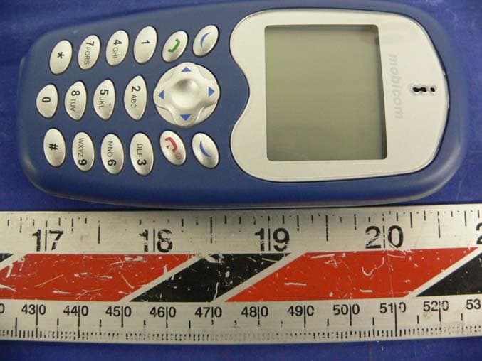
P8D-2188A
Aug 24, 2005850/1900 MHz GSM Mobile Phone
Equipment Class
PCE - PCS Licensed Transmitter held to ear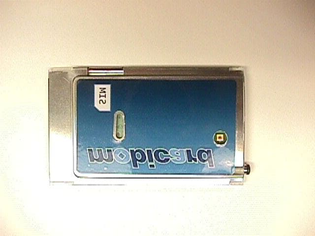
P8D-C6M88I
Jan 21, 2003GSM/GPRS 900/1900 PCMCIA Card
Equipment Class
PCB - PCS Licensed Transmitter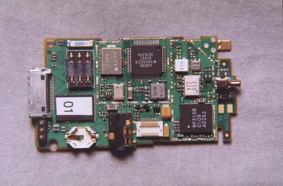
P8D-C6288I
May 08, 2002Dual Band PCS/GSM Flip-Phone
Equipment Class
PCE - PCS Licensed Transmitter held to ear