P8D-C6M88IGSM/GPRS 900/1900 PCMCIA Card
Mobicom Corporation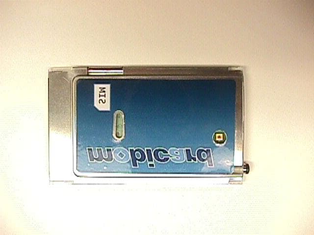
Click to zoom
Application Details
- Equipment Class
- PCB - PCS Licensed Transmitter
- Date of Grant
- Jan 21, 2003
- Application Purpose
- Original Equipment
- Date of Application
- Aug 14, 2002
- Equipment Note
- GSM/GPRS 900/1900 PCMCIA Card
- Frequency Range
- 1850.20000000 - 1909.80000000
- Company
- Mobicom Corporation
- Country
- United States
Documents & Files
Document Text
Text extracted from the exhibit documents filed with the FCC. Open a document above to read the original.
Users Manual
D R A F T C O P Y FCC ID: P8D-C6M88I - 1 - M88i Installation Guide D R A F T C O P Y FCC ID: P8D-C6M88I - 2 - Emergency Calls Please contact your service provider for the information about the availability of Emergency Calls. The MOBICARD M88 supports Emergency Calls with or without a SIM card inserted. However the M88 must be plugged into a computer or handheld device, powered up and have a headset plugged into it. If you are outside the coverage are of a GSM network, then Emergency Calls will not work. Do not rely on the M88 as your sole means of contacting Emergency Services. The procedure for generating an Emergency Call will depend on the application/service currently in use and the network you are connected to. It is recommended that you familiarize yourself with the appropriate procedures required to generate an Emergency Call. When connected to an Emergency Operator, you should have details of your telephone number and location on hand. M88 Safety Information The M88 is designed to operate only when plugged into a PCMCIA Type II PC card slot, within the confines of a computer or handheld device. The M88 derives its power from the computer or handheld power supply. Operation outside this environment, and/or with an alternative power supply, may infringe the type approval granted for this product, as well as potentially voiding the safety advice given below, and consequently should not be undertaken. The correct installation pr ocedure for the card must be adhered to at all times. The module operates at SELV limits, and it is the installer’s responsibility to make sure that all hazardous voltages have been isolated from the SELV circuitry, and that all safety requirements have been met to the appropriate standards. D R A F T C O P Y FCC ID: P8D-C6M88I - 3 - Further, it is the installers responsibility to ensure that the safety isolation barriers of the intended host equipment are not compromised by the installation of the card. The M88 radiates radio frequency signals in the 900 MHz and 1800 MHz frequency bands. The following recommendations are in line with guidelines concerning public exposure to radio frequency electromagnetic energy, issued by various European and International agencies. Unlike a mobile phone the transmitter on the M88 would not normally be used close to the head and therefore high field strength is not usually encountered. Using the M88 is similar to using a mobile with a handsfree kit. However, take care to avoid placing any part of your body in proximity to the antenna on the M88, while the M88 is operating. D R A F T C O P Y FCC ID: P8D-C6M88I - 4 - Introduction Congratulations on your purchase of the MOBICARD M88 dual-band GPRS modem from Mobicom Corporation. The M88 provides wireless GPRS data services and GSM voice services in a single card. With the M88 you can make and receive voice calls, send and receive SMS, use email, and surf the Internet with high-speed GPRS data connections. Components Your MOBICARD M88 box should contain the following items: • Warranty registration card • M88 installation guide (this manual) • CD-ROM with application software • M88 PCMCIA card • Handsfree headset You should notify your dealer immediately of any missing items. For the latest informatio n on the use of this product, please go to: www.mobicomcorp.com/M88/ updates Before installing, please complete the warranty registration card supplied with the M88, and return it to Mobicom Corporation. INSERT PICTURE OF CARD HERE D R A F T C O P Y FCC ID: P8D-C6M88I - 5 - System Requirements For use in laptops or Pocket PCs: • Free compatible type II PC card slot. PCMCIA/JEIDA PC Card Standard 6.1. • Voice and GPRS data enabled SIM. For Laptops: • Pentium II 266 or higher. • Windows 95, 98, NT, 2000, XP, Millennium. • At least 40Mb of free hard disk space. • At least 64Mb of RAM. • CD-ROM drive. For data, Internet and email applications: • Browser and email client software. • Dial up networking, configured for your Internet Service Provider. D R A F T C O P Y FCC ID: P8D-C6M88I - 6 - Installing the M88 in a laptop computer. This section explains how to install your M88 in a laptop computer. It is recommended that all important files are backed up prior to installation. Inserting the SIM card The M88 requires a SIM card, which is provided by your mobile phone service provider. This contains the telephone number that the M88 will use, as well as other customer information. Your SIM card must be enabled for all of the services you want to use, such as Voice, Data, and GPRS. To insert the SIM card: • Slide the SIM card into the socket on the side of the M88. Make sure the orientation is as shown and the contacts face down. There is a notch on one corner of your SIM card that will ensure the orientation is correct. INSERT PICTURE OF SIM CARD INSERT PICTURE OF SIM INSERTION WITH CARD D R A F T C O P Y FCC ID: P8D-C6M88I - 7 - Insert the M88 into one of the empty PCMCIA card slots. The card should be inserted with the SIM side up. Push the card in fully, but do not force it. After proper insertion, the laptop should detect the card and automatically install the proper Windows driver for the M88. The M88 should be installed as a Standard PCMCIA Modem. SHOW A PICTURE OF THE CARD BEING INSERTED INTO A LAPTOP D R A F T C O P Y FCC ID: P8D-C6M88I - 8 - Installing Phone Tools software • Insert the M88 CD-ROM into the drive. • Double click the CD-ROM icon in the My Computer folder. • Double click on the folder of the language that you want to install. • Double click on the folder named Disk1. • Double click on the file Setup.exe. • Follow the on screen installation instructions. Using your M88 This section explains some the general operational features of the M88. The fully retractable antenna The M88 is supplied with a fully retractable dual band antenna. During normal operation the antenna should be fully extracted. When not in use the antenna should be inserted back into the M88. SHO…
Text truncated - open the document above for the full version.
Users Manual
Emergency Calls Please contact your service provider for the information about the availability of Emergency Calls. The MOBICARD M88i supports Emergency Calls with or without a SIM card inserted. However the M88 must be plugged into a computer, powered up and have a headset plugged into it. If you are outside the coverage are of a GSM network, then Emergency Calls will not work. Do not rely on the M88i as your sole means of contacting Emergency Services. The procedure for generating an Emergency Call will depend on the application/service currently in use and the network you are connected to. It is recommended that you familiarize yourself with the appropriate procedures required to generate an Emergency Call. When connected to an Emergency Operator, you should have details of your telephone number and location on hand. M88i Safety Information The M88 is designed to operate only when plugged into a PCMCIA Type II PC card slot, within the confines of a computer. The M88i derives its power from the computer. Operation outside this environment, and/or with an alternative power supply, may infringe the type approval granted for this product, as well as potentially voiding the safety advice given below, and consequently should not be undertaken. The correct installation procedure for the card must be adhered to at all times. The module operates at SELV limits, and it is the installer's responsibility to make sure that all hazardous voltages have been isolated from the SELV circuitry, and that all safety requirements have been met to the appropriate standards. 1 Further, it is the installers responsibility to ensure that the safety isolation barriers of the intended host equipment are not compromised by the installation of the card. The M88i radiates radio frequency signals in the 1900 MHz frequency band. Unlike a mobile phone the transmitter on the M88i would not normally be used close to the head and therefore high field strength is not usually encountered. Using the M88i is similar to using a mobile with a handsfree kit. However, take care to avoid placing any part of your body in proximity to the antenna on the M88i, while the M88i is operating. FCC Notice and SAR StatementFor the M88iFCC ID: P8D-C6M88IThis device complies with part 15 of the FCC Rules. Operation is subject to the condition that this device does not cause harmful interference. NOTE: This equipment has been tested and found to comply with the limits for a Class B digital device, pursuant to part 15 of the FCC rules. These limitsare designed to provide reasonable protection against harmful interference in a residential installation. This equipment generates and uses radio frequency energy and, if not used in accordance with the instructions, may cause harmful interference to radio communications. However, there is no guarantee that interference will not occur in a particular installation. It this equipment does cause harmful interference to radio to TV reception, which can be determined by turning the unit off and on, the user is encouraged to try to correct the interference by one or more of the following measures. Reorient or relocate the antenna. Increase the separation between the equipment and the receiver. Connect the equipment into an outlet on a circuit different form that to which the receiver is connected. Consult the dealer or an experienced radio/TV technician for help. Specific Absoption Rate SAR is a value that corresponds to the relative amount of RF energy absorbedby the wireless user. The FCC of the United States sets SAR limits. Tests for SAR values are conducted using FCC approved operating positions and multiple laptop configurations. Tests are run at the highest possible power levels. The highest reported SAR levels for this PCMCIA card are in full complciance with the FCC limits. SAR compliance is limited to laptop computer installations. 2 Troubleshooting If you have trouble using your M88i, this section may help you identify the problem. If you need further assistance, you can contact Mobicom Corporation at 888-834-0602. General Checks Make sure the M88i is properly inserted into the PCMCIA card slot of the laptop. Check to see that the SIM is inserted correctly. Check the signal strength icon on the Phone Tools interface, to ensure that there is enough signal from the GSM network. Introduction Congratulations on your purchase of the MOBICARD M88i GPRS modem from Mobicom Corporation. The M88i provides wireless GPRS data services and GSM voice services in a single card. With the M88i you can make and receive voice calls, send and receive SMS, use email, and surf the Internet with high-speed GPRS data connections. Components Your MOBICARD M88i box should contain the following items: Warranty registration card M88i installation guide (this manual) CD-ROM with application software M88i PCMCIA card Handsfree headset You should notify your dealer immediately of any missing items. For the latest information on the use of this product, please go to: www.mobicomcorp.com/M88/updates Before installing, please complete the warranty registration card supplied with the M88i, and return it to Mobicom Corporation. 310 System Requirements For use in laptop PCs: Free compatible type II PC card slot. PCMCIA/JEIDA PC Card Standard 6.1. Voice and GPRS data enabled SIM. Pentium II 266 or higher. Windows 95, 98, NT, 2000, XP, Millennium. At least 40Mb of free hard disk space. At least 64Mb of RAM. CD-ROM drive. For data, Internet and email applications: Browser and email client software. Dial up networking, configured for your Internet Service Provider. Using Phone Tools with the M88i To launch the Phone Tools application software, double click on the mobile Phone Tools shortcut on your desktop. The first time you run Phone Tools, the software will be configured for you. Just follow the on screen instructions. When Phone Tools starts running, a picture of a phone will be displayed. This phone is the software interface used …
Text truncated - open the document above for the full version.
Cover Letter(s)
July 18, 2002 attn: TCB Services, Reviewing Engineer MET Laboratories, INC RE: CONFIDENTIALITY REQUEST FOR THE M88i FCC ID: P8D-C6M88I To Whom It May Concern: This letter serves as an official request for confidentiality under FCC Rule Section 0.459. Mobicom Corporation requests that the schematic diagrams, the block diagrams, circuit descriptions and the calibration procedures required to be submitted with this application be withheld from public review. These documents are company proprietary information that should not get into the possession of competitors. Please contact me if there is any information you may need. Sincerely, Joe Murphy Senior Testing Engineer Mobicom Corporation
Cover Letter(s)
January 17, 2003 attn: TCB Services, Reviewing Engineer MET Laboratories, INC RE: CONFIDENTIALITY REQUEST FOR THE M88i FCC ID: P8D-C6M88I To Whom It May Concern: This letter serves as an official request for confidentiality under FCC Rule Section 0.459. Mobicom Corporation requests that the schematic diagrams, the block diagrams, operational descriptions (functional descriptions) and the parts list/tune up procedures (calibration procedures and parts list) required to be submitted with this application be withheld from public review. These documents are company proprietary information that should not get into the possession of competitors. Please contact me if there is any information you may need. Sincerely, Joe Murphy Senior Testing Engineer Mobicom Corporation
ID Label/Location Info
August 12, 2002 FCC ID: P8D-C6M88I
RF Exposure Info
The Nation's First Licensed Nationally Recognized Testing Laboratory Conceil canadien des nomes Organisme de certification accedite Standards Council of Canada Accredited Certification Organization TM MET Laboratories, Inc. Safety Certification - EMI - Telecom Environmental Simulation 914 WEST PATAPSCO AVENUE !! BALTIMORE, MARYLAND 21230-3432 !! PHONE (410) 354-3300 !! FAX (410) 354-3313 July 30, 2002 Mobicom Corporation 960 Holmdel Road, Bldg. II Holmdel, NJ 07733 Reference:GSM/GPRS 900/1900 PCMCIA Card Model M88i FCC ID: P8D-C6M88I Dear Mr. Murphy: Enclosed is the EMC SAR Evaluation Report for the Mobicom GSM/GPRS 900/1900 PCMCIA Card Model M88i. The was tested in accordance with the measurement procedures specified in FCC OET 65 Supplement C:01-01 and shown to be capable to be in compliance for localized specific absorption rate (SAR) for uncontrolled environment/general population exposure limits specified in ANSI/IEEE Std. C95.1-1992. Thank you for using the testing services of MET Laboratories. If you have any questions regarding these results or if MET can be of further assistance to you, please feel free to contact me. We appreciate your business and look forward to working with you again soon. Kindest Regards, MET LABORATORIES, INC. Marianne Bosley Documentation Department Enclosures: (\Mobicom Corporation\EMC12218-FCC SAR.wpd) DOCTEM-23 Jan 02 Certificates and reports shall not be reproduced except in full, without the written permission of MET Laboratories, Inc. While use of the National Voluntary Laboratory Accreditation Program (NVLAP) letters or the NVLAP Logo in this report reflects the MET Accreditation under the NVLAP Program, these letters, logo, or Statements do not claim product endorsement by NVLAP or any Agency of the U.S. Government. Mobicom CorporationGSM/GPRS 900/1900 PCMCIA Card Model M88iFCC ID: P8D-C6M88I July 30, 2002 MET# EMC12218FCCSARCopyright 2002, MET Laboratories, Inc.Page ii of vii Dosimetric Assessment Test Report for the GSM/GPRS 900/1900 PCMCIA Card Model M88i Tested And Evaluated In Accordance With FCC OET 65 Supplement C:01-01 MET REPORT: EMC12218-FCC SAR July 30, 2002 PREPARED FOR: Mobicom Corporation 960 Holmdel Rd., Bldg. II Holmdel, NJ 07733 PREPARED BY: MET Laboratories, Inc. 914 West Patapsco Avenue Baltimore, Maryland 21230-3432 Copyright 2002, MET Laboratories, Inc. This report shall not be reproduced except in full, without the express written consent of MET Laboratories, Inc., nor shall this report, or any copy thereof be provided to a competitor of MET Laboratories, Inc. Mobicom CorporationGSM/GPRS 900/1900 PCMCIA Card Model M88iFCC ID: P8D-C6M88I July 30, 2002 MET# EMC12218FCCSARCopyright 2002, MET Laboratories, Inc.Page iii of vii Dosimetric Assessment Test Report for the Mobicom Corporation GSM/GPRS 900/1900 PCMCIA Card Model M88i Tested And Evaluated In Accordance With FCC OET 65 Supplement C:01-01 MET REPORT: EMC12218-FCC SAR July 30, 2002 PREPARED FOR: Mobicom Corporation 960 Holmdel Road, Bldg. II Holmdel, NJ 07733 Report Prepared By:Report Reviewed By: ______________________________________________________________ Marianne T. Bosley Liming Xu EMC ADMINISTRATORTEST ENGINEER Final Review By: ________________________________ Christopher R. Harvey EMC LAB DIRECTOR Engineering Statement: The measurements shown in this report were made in accordance with the procedures specified in Supplement C to OET Bulletin 65 of the Federal Communications Commission (FCC) Guidelines [FCC 2001] for uncontrolled exposure. I assume full responsibility for the accuracy and completeness of these measurements, and for the qualifications of all persons taking them. It is further stated that upon the basis of the measurements made, the equipment evaluated is capable of compliance for localized specific absorption rate (SAR) for uncontrolled environment/general population exposure limits specified in ANSI/IEEE Std. C95.1- 1992. ________________________________ CHRISTOPHER R. HARVEY EMC LAB DIRECTOR SAR EVALUATION CERTIFICATE OF COMPLIANCE FCC ID: P8D-C6M88I APPLICANT: Mobicom Corporation EUT:GSM/GPRS PCS 1900 PCMCIA Card Date of Receipt:April 4, 2002 Device Category:GSM/GPRS PCS 1900 PCMCIA Card RF exposure environment:Uncontrolled RF Exposure category:Portable Power supply:Powered by PC Antenna:Retractable (Not operational in retractable mode) Production/prototype:Identical Prototype Measured Standards:PCS 1900 Modulation:GSM Crest Factor:GSM = 8 TX Range:GSM PCS 1900 1850.2 MHz - 1909.8 MHz RX Range:GSM PCS 19001930.2 MHz - 1989.8 MHz Used TX Channels:GSM PCS 1900:low: ch.512, center: ch. 660, high: ch. 810 Maximum RF Power Output:0.9 W EIRPGSM PCS 1900 (29.5 dBm) Maximum SAR Measurement:0.117 W/kg PCS GSM Body (Averaged over 1g) This wireless portable device has been tested in accordance with the measurement procedures specified in FCC/OET Bulletin 65 Supplement C (2001) and IEEE Std. 1528-200X (July 2001), and has been shown to be capable of compliance for localized specific absorption rate (SAR) for uncontrolled environment/general population exposure limits specified in ANSI/IEEE Std. C95.1 - 1992. I attest to the accuracy of this data. All reported measurements were performed by me, or were made under my supervision, and are correct to the best of my knowledge and belief. I assume full responsibility for the completeness of these measurements and vouch for the qualifications of all persons taking them.. I also certify that no party to this application has been denied the FCC benefits pursuant to Section 5.301 of the Anti-Drug Abuse Act of 1988, 21 U.S.C. 862. Chris Harvey Director, EMC Laboratory APPLICANT NAME AND ADDRESS:DATE OF TEST: May 10, 2002 Mobicom CorporationTEST LOCATION: MET LABORATORIES INC. 960 Holmdel Road, Bldg. II914 West Patapsco Avenue Holmdel, NJ 07733Baltimore, Maryland 21230 Mobicom CorporationGSM/GPRS 900/1900 PCMCIA Card Model M88iFCC ID: P8D-C6M88I July 30, 2002 MET# EMC12218FCCSARCopyright 2002, MET Laboratories, Inc.Page v…
Text truncated - open the document above for the full version.
RF Exposure Info
IMMERSIBLE SAR PROBE CALIBRATION REPORT Part Number: IXP – 050 S/N 0082 March 2002 Indexsar Limited Oakfield House Cudworth Lane Newdigate Surrey RH5 5DR Tel: +44 (0) 1306 631 233 Fax: +44 (0) 1306 631 834 e-mail: [email protected] 2 INTRODUCTION This Report presents measured calibration data for a particular Indexsar SAR probe (S/N 0082) and describes the procedures used for characterisation and calibration. Indexsar probes are characterised using procedures that, where applicable, follow the recommendations of CENELEC [1] and IEEE [2] standards. The procedures incorporate techniques for probe linearisation, isotropy assessment and determination of liquid factors. Calibrations are determined by comparing probe readings with theoretical computations in canonical test geometries, using normalised power inputs. Each step of the calibration procedure and the equipment used is described in the sections below. CALIBRATION PROCEDURE 1. Equipment Used For the first part of the calibration procedure, the probe is placed in a calibration jig as pictured in Figure 1. In this position the probe can be rotated about its axis by a belt driven by a stepper motor. The probe is attached to an amplifier that is connected via an optical cable to a PC. A schematic representation of the test geometry is illustrated in Figure 2. A balanced dipole (900 or 1800 MHz) is inserted horizontally into the bracket attached to a second belt (Figure 1). The dipole also can be rotated about its axis. A cable connects the dipole to a signal generator, via a coupler and power meter. The signal generator is used to output a signal of 900 (or 1800) MHz at constant power, which is monitored on the power meter. The probe is positioned so that its sensors line up with the rotation center of the dipole. By recording E-field measurements as both the probe and the dipole are rotated, the spherical isotropy of the probe can be determined. The calibration process requires E-field measurements to be taken in air, in 900 MHz simulated brain liquid and in 1800 MHz simulated brain liquid. When it is necessary to place the probe in liquid, a rectangular box made from PMMA (200mm internal width, 200mm internal height and 100mm internal depth; wall thickness 4mm) is filled with the appropriate liquid and positioned on the stand so that the probe tip is centered within the liquid (Figure 1). The box is positioned so that its outer surface is 2mm from the dipole. 2. Linearising probe output The probe channel output signals are linearised in the manner set out in Refs [1] and [2]. The following equation is utilized for each channel: U lin = U o/p + U o/p 2 / DCP(1) 3 where U lin is the linearised signal, U o/p is the raw output signal in voltage units and DCP is the diode compression potential in similar voltage units. DCP is determined from fitting equation (1) to measurements of U lin versus source feed power over the full dynamic range of the probe. The DCP is a characteristic of the schottky diodes used as the sensors. For the IXP-050 probes the DCP values are typically 0.10V (or 20 in the voltage units used by Indexsar software, which are V*200). 3. Optimizing channel sensitivity factors in air The first step of the calibration process is to calibrate the Indexsar probe to a W&G EMR300 E-field meter in air. The principal reasons for this are to balance the channels in air and to obtain air factors that are used in subsequent steps of the calibration procedure. The probe and a 900 MHz standard dipole are positioned in the calibration jig as outlined in the section above. With the Indexsar probe located in air, individual channel output voltages are recorded as probe and dipole are rotated. An ‘air factor’ is applied to each of the probe’s three channels in order to equilibrate the peak magnitudes of each channel. A multiplier is applied to factors to bring the magnitudes of the average E-field measurements as close as possible to those of the W&G probe. The following equation is used (where output voltages are in units of V*200): E air 2 (V/m) = U linx * Air Factor x + U liny * Air Factor y + U linz * Air Factor z (2) It should be noted that the IXP-050 probes are optimised for use in t issue simulating liquids and do not behave isotropically in air. 4. 900 MHz Liquid Calibration The second phase of calibration requires the channel output voltages of the Indexsar probe to be measured in a box filled with 900 MHz simulated brain liquid. The box of liquid is placed on the stand as described above and as pictured in Figure 1. Channel outputs for the different orientations of probe and dipole are recorded and entered into a spreadsheet. These measurements are multiplied by the previously determined air factors. Another factor, referred to as the ‘liquid factor’ is also applied to the measurements of each channel. The magnitude of the liquid factor for each channel is selected so as to optimise the isotropy of the probe (i.e. equilibrate the peak magnitudes of the three channels) in the liquid. The following equation is used (where output voltages are in units of V*200): E liq 2 (V/m) = U linx * Air Factor x * Liq Factor x + U liny * Air Factor y * Liq Factor y + U linz * Air Factor z * Liq Factor z (3) 4 A chart of the spherical isotropy for probe 0082 is shown in Figure 3. The rotational isotropy is also determined. With the dipole at 90 to the probe axis the rotational isotropy for probe 0082 is +/- 0.25 dB (Figure 4). The final step of the 900 MHz calibration requires the measurement of SAR decay in a generic, spherical phantom and fitting the measured data to one of the two following theoretical predictions of the decay profile: a) SAR decay curve modelled using a 200mm diameter sphere energised by a balanced dipole in a ‘benchmark configuration’ developed as part of an Eureka Project [3]; or, b) SAR decay curve modelled by Flomerics [4] using a sphere and a balanced dipole in a similar test configuration. To measure SAR decay the…
Text truncated - open the document above for the full version.
RF Exposure Info
IMMERSIBLE SAR PROBE CALIBRATION REPORT Part Number: IXP – 050 S/N 0082 Calibration factors for 2450 MHz July 2002 Indexsar Limited Oakfield House Cudworth Lane Newdigate Surrey RH5 5DR Tel: +44 (0) 1306 631 233 Fax: +44 (0) 1306 631 834 e-mail: [email protected] 2 INTRODUCTION The calibration Report [1] supplied with this probe (S/N 0082) included the following calibration factors for 900MHz: Probe S/N 0082 at 900 MHzXYZ Air Factors300290330 DCP (V*200)202020 Liquid Factors0.3360.3470.347 At the time of the probe calibration report (March 2002) facilities were not available for probe calibration at 2450MHz. Indexsar have recently established waveguide- based probe calibration apparatus for this frequency and have now performed 2450MHz calibrations on seven probes similar to S/N 0082. The probes are less sensitive at 2450MHz than at 900MHz and the measured calibration factors reflect this. Based on the calibration measurements of seven similar probes in brain liquid (relative permittivity 38.13, conductivity 1.818 S/m), conversion factors that can be applied to the 900MHz calibration for use at 2450MHz have been deduced as below. The average of the factors required to convert a 900MHz calibration into a 2450MHz calibration for brain liquids was 1.53 with a standard deviation of 0.17. Based on these waveguide-based calibration data, the following factors would be appropriate for use with probe S/N 0082 at 2450MHz until the probe receives its next periodic calibration: Probe S/N 0082 at 2450 MHzXYZ Air Factors300290330 DCP (V*200)202020 Liquid Factors0.520.530.53 Prior to use, the validity of these factors should be confirmed by performing a validation measurement using a box phantom and 2450MHz dipole as described in IEEE1528 [1]. For use in body fluids, equivalent conversion factors can be deduced from calibration data for the same seven probes performed in body liquid (relative permittivity 55.28, conductivity 1.92 S/m). The average of the factors required to convert a 900MHz calibration into a 2450MHz calibration for body liquids was 1.71 with a standard deviation of 0.10. Other features of the probe calibration are as detailed in the previous probe calibration Report [1]. In particular, the axial and rotational isotropies listed for 900MHz are appropriate at 2450MHz. 3 WAVEGUIDE PERFORMANCE ASSESSMENT The waveguide apparatus referred to above has been constructed according to the guidelines offered in [2]. In particular, the dimensions and electrical properties of the matching windows have been accurately reproduced and the matching of the waveguides has been checked. Two waveguides with overlapping frequency ranges were compared at a frequency of 2000MHz and the uncertainty in the calibration factors between the two waveguides was 1%. The matching of the waveguides is indicated by return losses of typically –20dB over the frequency bands employed. Separately, the waveguides have been used to repeat calibrations on an Indexsar probe calibrated at the National Physical Laboratory [3]. The same calibration factors have been obtained in the Indexsar waveguides as with those reported by NPL using their own waveguides traceable to national standards. The agreement is within 2% for calibrations at 1800 and 1900MHz at which frequencies the NPL calibrations were performed. UNCERTAINTIES The uncertainties expected of waveguide calibrations are described in IEEE1528 [2]. Liquid properties used in the calibrations were measured at the time of calibration using the Indexsar DiLine dielectric measurement kit, which has uncertainties of around +/- 2% for both permittivity and conductivity for the types of simulant liquids used. REFERENCES [1] Immersible SAR probe calibration report Part No. IXP-050 S/N 0082. Indexsar Ltd. March 2002. [2] IEEE 1528, Recommended practice for determining the spatial-peak specific absorption rate (SAR) in the human body due to wireless communications devices: Experimental techniques. [3] Calibration report on SAR probe IXP-050 S/N 0071 from National Physical Laboratory. Test Report EF07/2002/03/IndexSAR. Dated 20 February 2002.
RF Exposure Info
Uniform E-Field Generation The method of guaranteeing the E-field is as follows. The jig used was as shown in Figure A.2 of the 4 th April draft of IEEE1528-200X and as described in section A.5.2.1 (dipole with flat phantom). The following description is given: “The first setup, shown in Figure A.2, consists of a thin plastic box filled with tissue simulating liquid that…
Text truncated - open the document above for the full version.
Contact Information
Applicant
John Huang
Technical Contact
MET Laboratories, Inc.Chris Harvey
[email protected]410-354-3300
914 West Patapsco Avenue · Baltimore, Maryland · United States
Non-Technical Contact
MET Laboratories, Inc.Marianne Bosley
[email protected]410-354-3300
Technical Specifications
| # | Rule Parts | Frequency Range | Power Output | Emission | Tolerance |
|---|---|---|---|---|---|
| 1 | 24E | 1.85 GHz - 1.91 GHz | 1 W | 243KGXW | 50.0000000000 Hz |
Other Applications from Mobicom Corporation
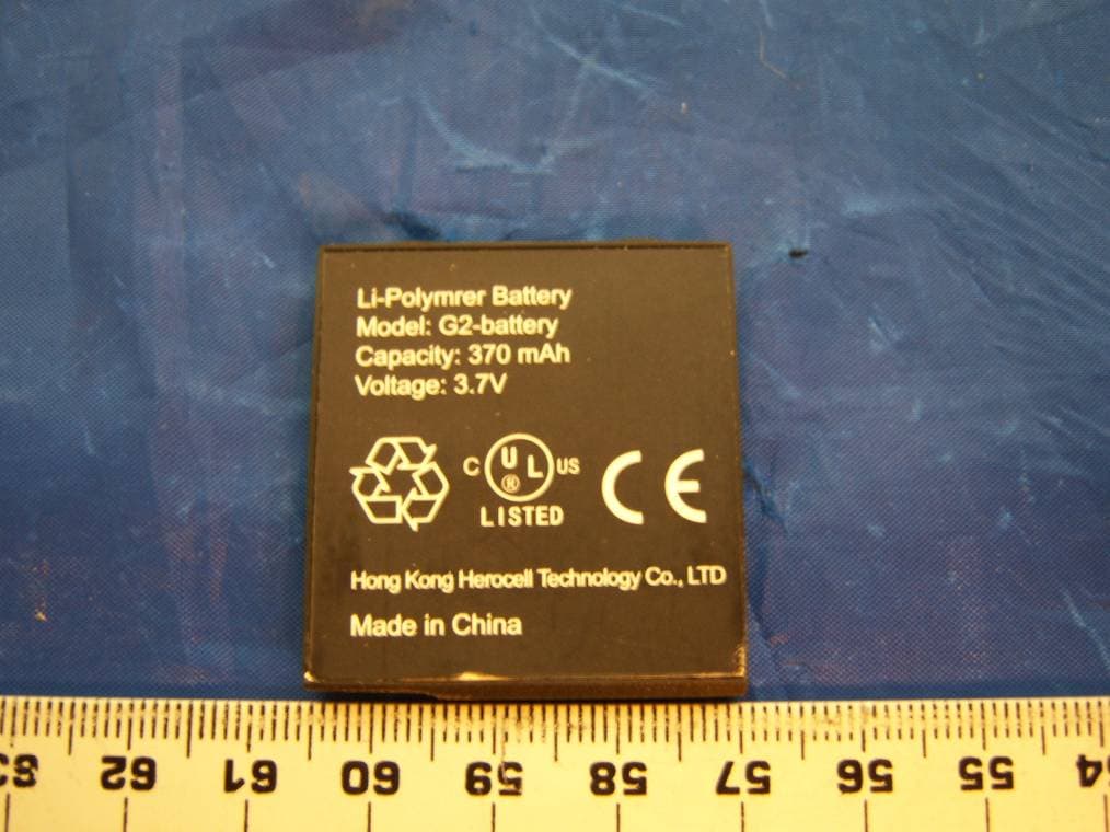
P8D-PLUSII
Mar 17, 2008GSM Handset with MP3 and Optional NFC/Paypass
Equipment Class
DXX - Part 15 Low Power Communication Device Transmitter
P8D-2189A
Jan 19, 2006850/1900 MHz GSM Mobile Phone
Equipment Class
PCE - PCS Licensed Transmitter held to ear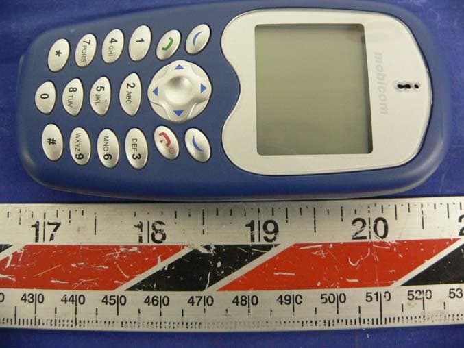
P8D-2188A
Aug 24, 2005850/1900 MHz GSM Mobile Phone
Equipment Class
PCE - PCS Licensed Transmitter held to ear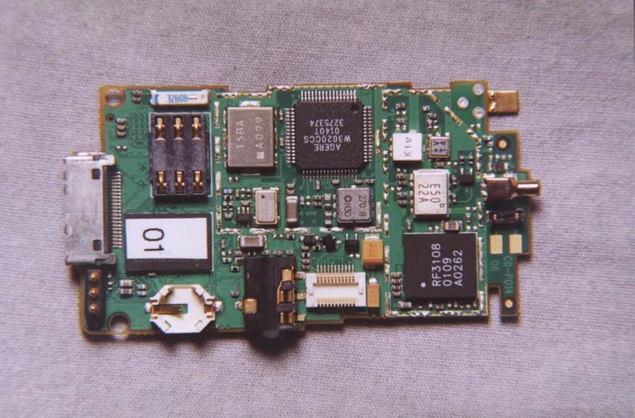
P8D-C6288I
May 08, 2002Dual Band PCS/GSM Flip-Phone
Equipment Class
PCE - PCS Licensed Transmitter held to ear
P8D-C6088I
May 07, 2002Dual Band PCS/GSM Flip-Phone
Equipment Class
PCE - PCS Licensed Transmitter held to ear