P8F800100DTR Series Reader
Digital Angel Corporation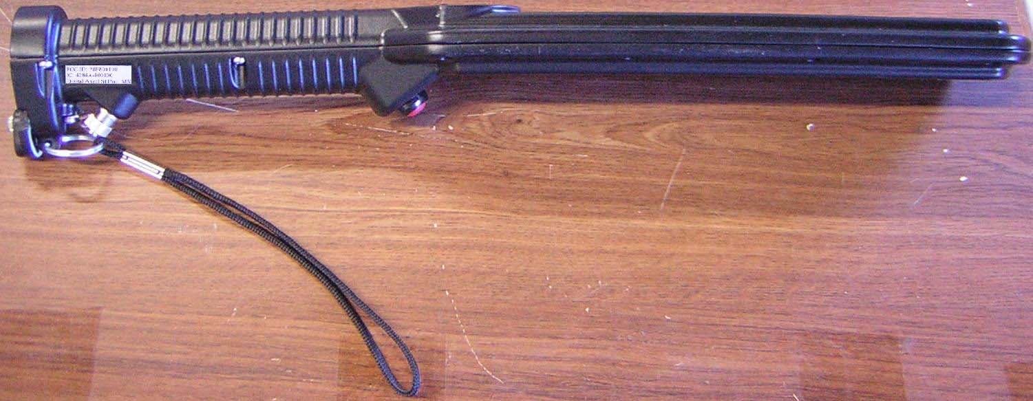
Click to zoom
Application Details
- Equipment Class
- DTS - Digital Transmission System
- Date of Grant
- Apr 30, 2007
- Application Purpose
- Original Equipment
- Date of Application
- Apr 30, 2007
- Equipment Note
- DTR Series Reader
- Frequency Range
- 2402.00000000 - 2480.00000000
- Company
- Digital Angel Corporation
- Country
- United States
Documents & Files
Document Text
Text extracted from the exhibit documents filed with the FCC. Open a document above to read the original.
Users Manual
DTR READER (ISO Compliant) OPERATING MANUAL Reads RFID Tags On: • Livestock • Pets • Fish • Custom Applications Page 1 Table of Contents I. Components 2 II. Getting Started 3 III. Operation 5 IV. Installing InfodexM 7 V. Connecting to a Host 8 VI. Using InfodexM 15 VII. Troubleshooting 21 VIII. Proper Use and Care 23 IX. Specifications and Warranty 24 X. FCC Statement 25 Page 2 I. Components The following DTR Reader components are available and can be ordered separately. 800.8001.00 Reader/Standard 802.1312.22 Test Tag 110.0060.00 Battery Pack 228.0230.00 Standard Cable 228.0049.00 Serial Coil Cable Also available but not pictured: DTR Holster (DTRH-01), IR5760 Charger. To order additional accessories and for kit information, please contact Digital Angel at 1-800-328-0118. Page 3 II. Getting Started Features of the reader • Can read up to 18,000 tags on a single battery charge • Wired (serial) or wireless (Bluetooth) operation • Capable of storing 510 RFID tags (DTR3 only) • Configurable using either a utility program or a communications program (DTR3 only) Battery information Type The battery in the kit is custom designed for the reader. The use of other commercial batteries WILL NOT activate the reader and could cause permanent damage. Installation To install the battery, remove the thumb screw and slide open the door on the end of the reader handle. After inserting the battery, close the door and tighten the thumb screw. Important: Only one end of the battery is designed to enter the chamber. If battery does not fit easily, turn it over and re-insert. Forcing the incorrect end of the battery into the chamber could damage the components. Page 4 Charging The battery should be fully charged before the first use and should only be charged with the supplied charger. The battery may be charged either within or outside the battery chamber. When leaving the battery within the battery chamber, loosen the battery door thumbscrew one turn and then slide the cover to expose the charging receptacle. 1) Plug the charger into a standard AC outlet. 2) Plug the charger cord into the battery receptacle. The charger will disconnect power to the reader. The reader cannot be used while the battery is charging. 3) Periodically monitor the progress. The Status light on the charger indicates the state of the battery. • Yellow = the battery needs charging. • Green = the battery is fully charged. The battery should fully charge in about two hours. It is not possible to overcharge the battery. 4) When the battery is charged, remove the charger and close the battery door. The reader is now ready for operation. Page 5 III. Operation Activate the reader Push the activation switch on the bottom of the reader to turn power on (allow five seconds for startup to complete). The red light on the top of the reader will be lit and will remain on while the reader is active. The reader will stay active for 60 minutes. After 60 minutes the reader will automatically shut down. Steady red: Power is on. Flashing red: Reader memory is more than 90% full (applies to DTR3 Readers only). Flashing blue: Reader is searching for wireless connection. Steady blue: Reader is connected to host. One green flash: A tag has been read. Red Light Blue Light Green Light Page 6 Reading tags Press the scanning switch and hold it until the tag has been successfully scanned. You must pass the reader within six inches of the ID tag. Be sure to release the switch before scanning the next tag. This allows the reader to return to scan mode. DTR3 Reader On a DTR3 Reader the tags are stored by default in memory on the reader. If a tag is successfully read and saved, the green indicator light will flash twice and the reader will beep twice. If the same tag is read twice in a row, the green indicator light will flash once and the reader will beep once but the tag will not be saved in memory. The tags are downloaded from the reader using the InfodexM utility. If the memory function is disabled the DTR3 Reader will operate the same as the DTR1 reader. DTR1 Reader The DTR1 reader does not contain any memory and the tags are immediately downloaded to a host device via either a serial or Bluetooth connection. Pre-test before scanning animals A test tag is been provided with the reader. Hold this tag in the palm of your hand and pass the reader over the tag. Storage Be careful that the power switch is not accidentally held in the “on” position during storage. If it is held on the reader battery will deplete and need to be re-charged. Page 7 IV. Installing Infodex ® M (DTR3 Readers only) Infodex®M is a utility that enables you to: • Configure the reader • Download tags from the reader to the utility • Export tag IDs to your computer Requirements • Windows 2000 or Windows XP • .NET Framework 2.0 or later (automatically installed for you during the utility installation process) • RS-232 serial port or Bluetooth connectivity Installation To install InfodexM: 1) Insert the InfodexM CD into the CD drive. The Welcome dialog should automatically appear. If it doesn’t, simply double-click the Setup.exe file on the CD. 2) Click Next. The Select Installation Folder dialog is displayed. 3) If you accept the default folder and user values, click Next. Otherwise, modify the values and then click Next. The Confirm Installation dialog is displayed. 4) To begin the installation process, click Next. 5) When the Installation Complete dialog is displayed, click Close. Page 8 V. Connecting To A Host Serial cable connection 1) Turn on the reader and then connect it to your host data collection device (PDA, computer, etc.) using the serial communication cable provided with the reader. 2) Configure the data collection software. If using a communications program such as HyperTerminal, use the following RS232 settings: • Baud rate: 9600 • Data bits: 8 • Parity: None • Stop bits: 1 • Flow: None If using InfodexM (DTR3 models only), start the utility by selecting Start > All Programs >…
Text truncated - open the document above for the full version.
Attestation Statements
TÜV America Inc. Phone: (651) 638-0297 19333 Wild Mountain Road Fax: (651) 638-0298 Taylor Falls, MN 55084 E-mail: [email protected] www.TUVamerica.com Management Service • Product Service • Industry Service • Automotive • BABT TÜV America Inc. is a subsidiary of TÜV SÜD Group. TÜV AMERICA INC 19333 WILD MOUNTAIN ROAD TAYLORS FALLS, MINNESOTA 55084-1786 ENGINEERING STATEMENT For Certification of Digital Angel Corporation Cattle Paddle DTR Model No: DTR1 P/N 800.8001.00 FCC ID: P8F800100 FRN: 0009788043 IC: 4284A-800100 I am an Electromagnetic Compatibility Engineer for TÜV AMERICA INC, Taylors Falls, Minnesota. My education and experience are a matter of record with the Federal Communications Commission. TÜV AMERICA INC has been authorized by Zeke Mejia, Chief Technology Officer, of Digital Angel Corporation, to make Certification measurements of the above mentioned equipment. I attest that all testing done under my supervision was done in accordance with, and that the EUT fulfills the requirements of, the Federal Communications Commission's CFR 47 Part 15.209 and Industry Canada's RSS 210 Issue 6. Joel T. Schneider Senior Engineer Minnesota Wild River Lab TÜV America Product Service Tel: 651 604 4582 Fax: 651 638 0298 [email protected] Dated: 30 June 2006
External Photos
Front Back Left Side including handle (Serial number side) Right Side including handle (FCC ID side) Battery End – Cover Closed Battery End – Cover Open
ID Label/Location Info
Digital Angel Corporation Cattle Paddle DTR Model 800800100 FCC / IC Label Placement World Headquarters USA Customer Service 490 Villaume Avenue Phone – (800) 328-0118 South St. Paul, MN 55075-2445 USA Fax – (800) 328-4565 Phone: (651) 455-1621 Computer Access – (651) 455-1209 Fax: (651) 455-0413 The FCC identifying label for the DTR Cattle Paddle will be located on the handle of the transceiver. The label will be laid out with the following information as follows: Label that appears on the transceiver handle: Label that appears in the user’s manual: Animal Management Products Worldwide Since 1945 FCC ID: P8F800100 IC: 4284A-800100 DigitalAngelStPaul,MN Digital Angel Corporation So. St. Paul, MN 55075-2443 Phone: 1-800-328-0118 Fax: 1-800-328-4565 FCC ID: P8F800100 This device complies with Part 15 of the FCC rules. Operation is subject to the following two conditions: 1) This device may not cause harmful interference, and, 2) This device must accept any interference received including interference that may cause undesired operation. Caution to the user: Any changes or modifications to the reader other than specified by this manual or Digital Angel Corporation could void the user’s authority to operate the reader. Industry Canada Registration ID IC: 4284A-800100 Digital Angel Model number label Located on handle, opposite side of FCC / IC ID labels
Internal Photos
Entire Reader Inside Inside of Handle Main Board Front Main Board Additional Front View Main Board Front Close up View Main Board Back Antenna Front Bluetooth Separated Front Bluetooth Front Bluetooth Back Bluetooth Board Connections Battery Cover Closed Battery Cover Open Battery External
Operational Description
World Headquarters USA Customer Service 490 Villaume Avenue Phone – (800) 328-0118 South St. Paul, MN 55075-2445 USA Fax – (800) 328-4565 Phone: (651) 455-1621 Computer Access – (651) 455-1209 Fax: (651) 455-0413 Theory of Operation Statement Antenna Description The antenna used with the Destron Technologies reader is a tuned LC circuit. It is made up of two coils and some series capacitors tuned to peak the antenna current at 134.2 KHz. Operational Description The Cattle Paddle DTR reader is designed to read RFID transponders that operate at a frequency of 134.2 KHz. The reader sends out a magnetic field through the antenna coil at that frequency. Using the receiver coil antenna, the signal is received back from the transponder, sent through filters and decoded by the microprocessor. The resultant transponder ID is then sent out the RS232 port or the Blue Tooth Serial connection to a host computer. The Cattle Paddle DTR reader is designed to operate on an internal rechargeable battery. Circuit Functions Main Board The main board contains the microprocessor and support circuitry for I/O functions such as serial communications through the RS232 port and communication through the Blue Tooth serial interface board. The main board also contains the tuned amplifier with circuitry to decode all ISO compliant tags. The CPU generates the 134.2 kHz signal by dividing the main clock signal. Tuning Board The tuning board contains the series tuning capacitors for driving the sending and receiving coil antennas to peak at 134.2 kHz. Blue Tooth Board This proprietary board allows us to communicate with a host computer using a Blue Tooth Serial Connection. This eliminates the need for an RS232 cable. Animal Management Products Worldwide Since 1945 CONFIDENTIAL
RF Exposure Info
09 April 2007 AmericanTCB 6731 Whittier Avenue McLean VA 22101 Attn: Director of Certification RE: Declaration of Compliance to RF Exposure Limits for Humans Cattle Paddle DTR reader RF Exposure Statement 1. Standard Applicable According to FCC 1.1307 (b)(1) and IC RSS-102, systems operating under the provisions of this section shall be operated in a manner that ensure that the public is not exposed to radio frequency energy level in excess of the Commission’s guideline. This is a portable device operating in 2402-2480 MHz range. 2. Measurement Result: This is a portable device and the max peak output power is –13.7 dBm (.000043 W). Lower than low threshold 60/f GHz mW (24 mW), d<2.5 cm, general population category. The SAR measurement is not necessary. Joel T. Schneider Senior Engineer Minnesota Wild River Lab TÜV America Product Service Tel: 651 604 4582 Fax: 651 638 0298 [email protected]
Test Report
TÜV SÜD AMERICA INC 19333 Wild Mountain Road Taylors Falls MN 55084 Tel: (651) 638-0297 Fax: (651) 638-0298Rev. 120506 TEST RESULT SUMMARY FCC Part 15 Subpart C Section 15.247 FCC Part 15 Subpart C Section 15.207 Industry Canada RSS-210 Issue 6 Industry Canada RSS-Gen Issue 1 MANUFACTURER'S NAME Digital Angel Corporation NAME OF EQUIPMENT DTR Series Reader MODEL NUMBER(S) TESTED 800800100 MANUFACTURER'S ADDRESS 490 Villaume Avenue South St. Paul, MN 55075 TEST REPORT NUMBER WC606308 TEST DATE(S) 15 March 2005, 08 – 09 November 2006 According to testing performed at TÜV SÜD America Inc, the above mentioned unit is in compliance with the applicable electromagnetic compatibility (EMC) portions of the requirements defined in FCC Part 15 Subpart C Sections 15.247 and 15.207 and IC RSS-210 Issue 6 and RSS-Gen Issue 1 It is the manufacturer's responsibility to assure that additional production units of this model are manufactured with identical electrical and mechanical characteristics. Any modifications necessary for compliance made during testing on the above mentioned date(s) must be implemented in all production units for compliance to be maintained. TÜV SÜD America Inc, as an independent testing laboratory, declares that the equipment tested as specified above conforms to the applicable EMC requirements of FCC Part 15 Subpart C Sections 15.247 “Operation within the bands 902–928 MHz, 2400–2483.5 MHz, and 5725–5850 MHz; General requirements.” and 15.207 “Conducted Limits” and IC RSS-210 Issue 6 “Low-power Licence-exempt Radiocommunication Devices (All Frequency Bands): Category I Equipment” and IC RSS-Gen “General Requirements and Information for the Certification of Radiocommunication Equipment”. Date: 05 December 2006 Location: Taylors Falls MN Ross Johnson & Joe Sausen Joel Schneider USA EMC Technicians Sr. EMC Engineer Not Transferable TÜV SÜD AMERICA INC 19333 Wild Mountain Road Taylors Falls MN 55084 Tel: (651) 638-0297 Fax: (651) 638-0298Rev. 120506 EMC TEST REPORT Test Report File No. : WC606308 Date of issue: 05 December 2006 Model / Serial No(s) Tested : 800800100 / 0631.1029 & 0305,002 Product Type : DTR Series Reader, Hand-Held Wireless ISO Reader Applicant : Digital Angel Corporation Manufacturer : Digital Angel Corporation License holder : Digital Angel Corporation Address : 490 Villaume Avenue South St. Paul, MN 55075 Test Result : Positive Negative Test Project Number References : WC606308 Total pages including Appendices : 53 TÜV SÜD AMERICA Inc reports apply only to the specific samples tested under stated test conditions. It is the manufacturer's responsibility to assure that additional production units of this model are manufactured with identical electrical and mechanical components. TÜV SÜD America Inc shall have no liability for any deductions, inferences or generalizations drawn by the client or others from TÜV SÜD America Inc issued reports. This report is the confidential property of the client. As a mutual protection to our clients, the public and ourselves, extracts from the test report shall not be reproduced except in full without our written approval. This report shall not be used by the client to claim product endorsement by NVLAP, NIST, or any agency of the US government. TÜV SÜD AMERICA Inc and its professional staff hold government and professional organization certifications and are members of AAMI, ACIL, AEA, ANSI, IEEE, NARTE, and VCCI. WC606308Page 1 of 53 TÜV SÜD AMERICA INC 19333 Wild Mountain Road Taylors Falls MN 55084 Tel: (651) 638-0297 Fax: (651) 638-0298Rev. 120506 D I R E C T O R Y Documentation Page(s) Directory 2 Test Regulations, Environmental conditions, Power supply 3 Test Data and Results: FCC IC 20 dB Bandwidth 15.247(a)(1) RSS-210 A8.1(1) 4 - 7 Carrier frequency separation 15.247(a)(1) RSS-210 A8.1(2) 8 - 9 Number of hopping channels FCC 15.247(a)(1)(iii) RSS-210 A8.1(4) 10 - 11 Time of channel occupancy FCC 15.247(a)(1)(iii) RSS-210 A8.1(4) 12 - 14 Maximum peak output power FCC 15.247(b)(1) RSS-210 A8.4(2) 15 - 19 Spurious Emissions 15.247(d) RSS-210 A8.5 20 - 30 Conducted Limits - AC Power lines 15.207(a) RSS-Gen 7.2.2 31 - 36 Test area diagram(s) 37 - 38 Test setup photo(s) 39 - 41 Test Operation Mode, Configuration of the device under test 42 Deviations From Standard, General Remarks, Summary 43 Appendix A Constructional Data Form & Block Diagram 44 - 51 Appendix B Measurement Protocol 52 - 53 Sign Explanations: - not applicable - applicable Directory 2 Test Regulations, Environmental conditions, Power supply 3 WC606308Page 2 of 53 TÜV SÜD AMERICA INC 19333 Wild Mountain Road Taylors Falls MN 55084 Tel: (651) 638-0297 Fax: (651) 638-0298Rev. 120506 EMC TEST REGULATIONS: The tests were performed according to the following regulations : - EN 50081-1 / 1991 - EN 55014-2: 1997 + Amendment A1: 2001 - Category __ - EN 55024: 1998 + Amendments A1: 2001 + A2: 2003 - EN 60601-1-2: 2001 - EN 61000-6-1: 2001 - EN 61000-6-2: 2001 - EN 61326: 1997 + Amendments A1: 1998 + A2: 2001 + A3: 2003 - EN 61800-3: 1996 + Amendment A11: 2000 - ETS 300 683: 1997 - ETS 300 683: 1997 - ETSI EN 301 489-3 V1.4.1: 2002 - EN 300 220-3 V1.1.1 - EN 300 330-2 V1.1.1 - FCC Part 15 Subpart C Section 15.207 - FCC Part 15 Subpart C Section 15.209 - FCC Part 15 Subpart C Section 15.247 - FCC Part 15 Subpart C Section 15.249 - IC RSS-210 Issue 6 - IC RSS-Gen Issue 1 - IC RSS-Gen Issue 1 ENVIRONMENTAL CONDITIONS IN THE LAB Actual Temperature: : 12 - 21 °C Atmospheric pressure : 98 kPa Relative Humidity : 25 - 36 % POWER SUPPLY UTILIZED Power supply system : 6 VDC Internal Battery (normal use) : 110 VAC / 60 Hz - 1 phase to DC battery charger WC606308Page 3 of 53 TÜV SÜD AMERICA INC 19333 Wild Mountain Road Taylors Falls MN 55084 Tel: (651) 638-0297 Fax: (651) 638-0298Rev. 120506 20 dB Bandwidth FCC 15.247(a)(1), IC RSS-210 A8.1(1) Test summary The requirements are: - MET - NOT MET 20 dB bandwidth = 800 kHz on low, mid, a…
Text truncated - open the document above for the full version.
Test Setup Photos
TÜV SÜD AMERICA INC 19333 Wild Mountain Road Taylors Falls MN 55084 Tel: (651) 638-0297 Fax: (651) 638-0298Rev. 120506 TEST SETUP FOR EMISSIONS TESTING WILD RIVER LAB Large Test Site Notes: 1. Items shown in dotted lines are located on the floor below the test area. It is 5 meters vertically from the ground floor to the test area. 2. 50 Hz, 60 Hz, and 400 Hz are power panels for alternating current. 3. The antenna may be positioned horizontally 3, 10 or 30 meters from the center of the turntable. 4. The circle is a 6.7 meter diameter turntable. 5. A ground plane is in the plane of this sheet. 6. The test sample is shown in the azimuthal position representing zero degrees. EUT 0 90270 180 60 Hz 50 Hz 400 Hz Shielded Enclosure ANTENNA WC606308Page 37 of 53 TÜV SÜD AMERICA INC 19333 Wild Mountain Road Taylors Falls MN 55084 Tel: (651) 638-0297 Fax: (651) 638-0298Rev. 120506 TEST SETUP FOR EMISSIONS TESTING WILD RIVER LAB Small Test Site (STS) EUT 180 270 90 0 60 Hz 50 Hz Turntable is 1.2 meters in diameter Enlarged View of Shelter (4 meters square) STS Building Shelter 3 meter antenna 10 meter antenna 30 meter antenna Turntable Control Cable Ground Screen (34 meters long x 12 meters wide) 8 meters WC606308Page 38 of 53 TÜV SÜD AMERICA INC 19333 Wild Mountain Road Taylors Falls MN 55084 Tel: (651) 638-0297 Fax: (651) 638-0298Rev. 120506 Test-setup photo(s): Radiated emissions test WC606308Page 39 of 53 TÜV SÜD AMERICA INC 19333 Wild Mountain Road Taylors Falls MN 55084 Tel: (651) 638-0297 Fax: (651) 638-0298Rev. 120506 Test-setup photo(s): Conducted emissions test - under test report number WC501242, 15 March 2005 WC606308Page 40 of 53 TÜV SÜD AMERICA INC 19333 Wild Mountain Road Taylors Falls MN 55084 Tel: (651) 638-0297 Fax: (651) 638-0298Rev. 120506 Test-setup photo(s): Conducted emissions test - under test report number WC501242, 15 March 2005 WC606308Page 41 of 53
Contact Information
Applicant
Zeke Mejia(CTO)
Technical Contact
TUV AmericaJoel Schneider
[email protected]651 694 4582
19333 Wild Mountain Road · Taylors Falls, Minnesota
Non-Technical Contact
TUV AmericaSusan Rupp
[email protected]651 694 4582
Test Firm
TUV SUD America - Product ServiceJoel Schneider
Technical Specifications
| # | Rule Parts | Frequency Range | Power Output |
|---|---|---|---|
| 1 | 15C | 2.40 GHz - 2.48 GHz | 42.00 µW |
Other Applications from Digital Angel Corporation
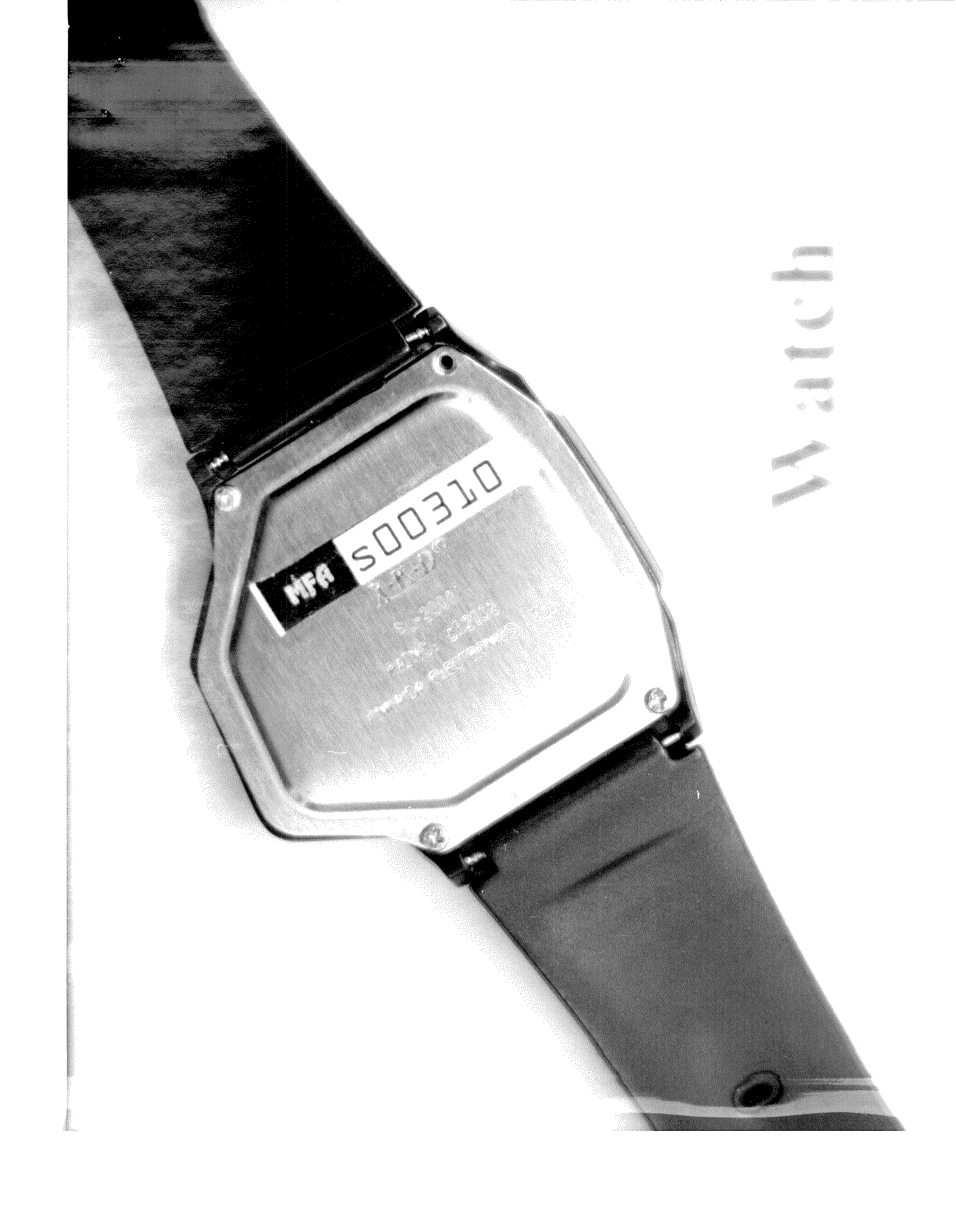
P8FCDPDWCH01
May 07, 2002Watch Transmitter
Equipment Class
DSC - Part 15 Security/Remote Control Transmitter
P8FCDPD-MON-02
May 07, 2002CDPD System Pager
Equipment Class
TNB - Licensed Non-Broadcast Station Transmitter