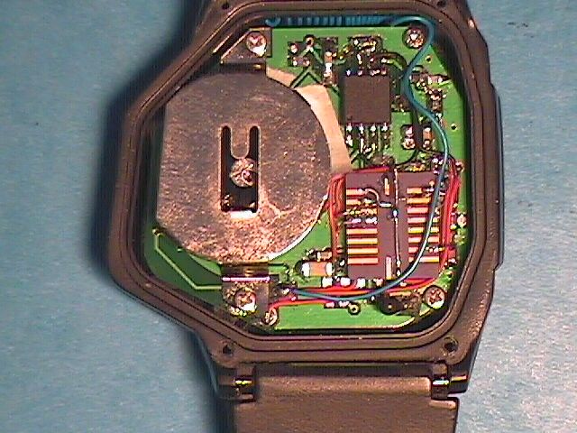
P8FCDPDWCH01Watch Transmitter
Digital Angel Corporation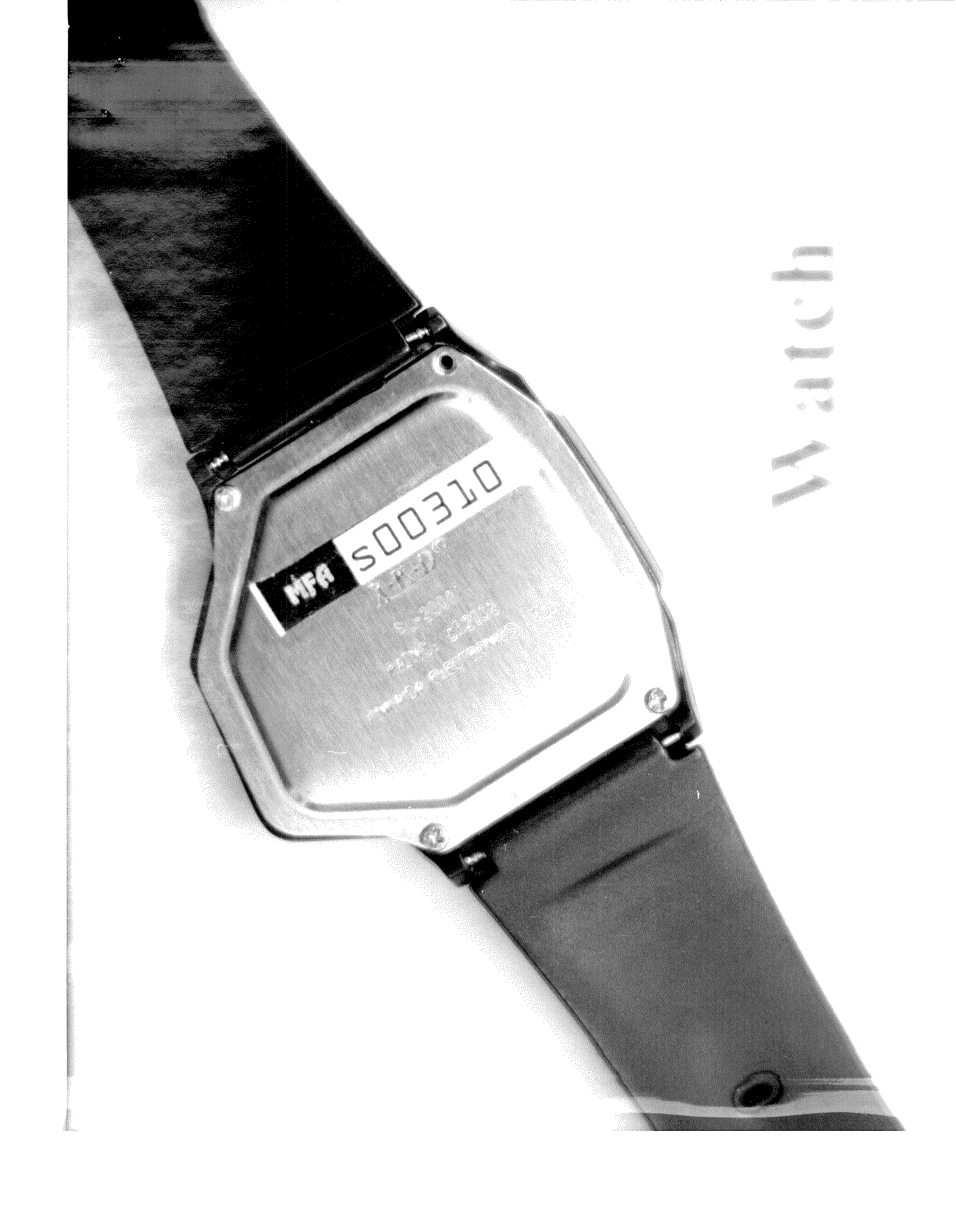
Click to zoom
Application Details
- Equipment Class
- DSC - Part 15 Security/Remote Control Transmitter
- Date of Grant
- May 07, 2002
- Application Purpose
- Original Equipment
- Date of Application
- May 07, 2002
- Equipment Note
- Watch Transmitter
- Frequency Range
- 314.80000000 - 315.20000000
- Company
- Digital Angel Corporation
- Country
- United States
Documents & Files
Document Text
Text extracted from the exhibit documents filed with the FCC. Open a document above to read the original.
Users Manual
Version 8.0 Quick Start Guide v 7.0 Digital Angel Corporation Page 2 Getting Started Step 1 Checking the Package Contents Make sure you have received the following items in the package. If any of these items are missing or damaged, contact the Digital Angel Product Support Line (see below): • Digital Angel monitor • Digital Angel ThermAlert watch • 115 volt AC adapter/wall charger • Car charger Digital Angel Product Support Line Telephone: 1-877-432-0830 Hours: 7:30 a.m. to 8:30 p.m. EST. After hours, you may leave a message and a Digital Angel Product Support Line specialist will return your call during business hours. In the event of an after hours emergency, you may leave an urgent message and your call will be returned as soon as possible. We can also be reached via email at [email protected] Quick Start Guide v 7.0 Digital Angel Corporation Page 3 Step 2 Getting Acquainted With Your Digital Angel Monitor Please take time to examine the diagram below and get acquainted with the components and features of your Digital Angel monitor. Emergency Button Enables the wearer to signal a distress call to the Digital Angel Operations Center. ON/OFF Switch—Slide up to turn ON, Slide down to turn OFF Antenna LED Status Lights The three LED status lights provide you with information about how your Digital Angel monitor is operating. • Power Status. A flashing red light means the monitor is powered up. A constant red light means the battery is low and requires charging. • Communication Status. A flashing green light means the monitor is in communication with the AT&T Wireless Network. • Battery Charging status. A constant red light appears while the battery is charging. A flashing red light (once every four seconds) indicates completion of the charging process. This device complies with Part 15 of the FCC Rules. Operation is subject to the condition that this device does not cause harmful interference. Step 3 Charging the Battery • You should charge the battery for a full six hours before beginning to use your Digital Angel monitor. Plug the AC adapter into your Digital Angel monitor, then into a 115V AC wall outlet to charge the battery. • The battery will supply adequate power for approximately 8 hours under normal use. The top LED light on the front of your Digital Angel monitor will show a constant red when the battery becomes low. Step 4 Getting Acquainted With Your Digital Angel ThermAlert Watch Please take time to examine the diagram below and get acquainted with the components and features of your Digital Angel watch. –INSERT: DIAGRAM OF THERMALERT WATCH- Quick Start Guide v 7.0 Digital Angel Corporation Page 4 LCD Digital Time Display The ThermAlert Watch features a fully functional digital clock that can be adjusted and reset. Time Adjustment/Reset Button ON/OFF Switch LCD RF Transmission Link Indicator When the temperature data transmission feature is activated, the indicator flashes at 18-second intervals, indicating active transmission of temperature data—via Radio Frequency (RF) link—from the ThermAlert Watch to the Digital Angel Monitor. The indicator does not appear when the temperature data transmission is deactivated or when the RF link is compromised. Mode Switch Switches between normal clock mode and stop-watch mode. Battery Compartment The ThermAlert Watch uses a non-replaceable battery that provides approximately two months of operation time when the temperature function enabled. This device complies with Part 15 of the FCC Rules. Operation is subject to the condition that this device does not cause harmful interference. Step 5 Turning on Your Digital Angel Monitor Once the battery is fully charged, turn on your Digital Angel monitor. When the communications status light begins blinking the monitor is properly communicating with the AT&T Wireless Network. This can take approximately 20 seconds after switching on your monitor although this varies by area. Move next to a window if the communications status light does not begin flashing. If the communications status light still does begin flashing this means that you do not have AT&T Wireless Network coverage in your area. Once the Digital Angel monitor is powered up, you should enable the temperature sensing function on the ThermAlert Watch and check the LCD Data Transmission Indicator to confirm (indicated by flashing at 18- second intervals) the RF link between the Watch and the Digital Angel monitor. Note: To maintain the integrity of the RF link, the distance between the ThermAlert Watch and Digital Angel monitor must be no more than 1.5 meters (approximately 4.9 feet). You are now ready to proceed with registering your Digital Angel monitor. Step 6 Registering Your Digital Angel Monitor In order to complete the registration process, you will need: • The EID of your Digital Angel monitor. The EID number is labeled on the back of the monitor. • Caregiver contact information including address, telephone number and email address. • Wearer information including address, telephone number, the established Temperature parameters and Location Boundary for the Wearer. • The User ID and Password of your choice required for access to all Digital Angel information requests via the Web site. • PIN number of your choice for telephone access to Digital Angel Alert Information Hotline Register your Digital Angel monitor by going to http://www.digitalangel.net and clicking the Beta Test button found in the upper right on the Digital Angel home page. You will be taken to the Digital Angel Registration page. Quick Start Guide v 7.0 Digital Angel Corporation Page 5 Now you’re ready to click the “REGISTER” button. This takes you to the Caregiver Profile page. Quick Start Guide v 7.0 Digital Angel Corporation Page 6 Enter all requested caregiver information; email address for receiving reports as well as alert notifications, portable email address (for receiving alert notifications), along with the User ID, Password, PIN number and Securi…
Text truncated - open the document above for the full version.
Block Diagram
Digital Angel CDPD Unit Block Diagrams GPS Module CDPD Module Local RF Receiver Module FallDown Sensor Module MCU --- DA CDPD System Micro-Controller Power supply / Mower Management System RF Transmitter Module Temperature Sensor Module Power Supply Watch Micro-controller DA Watch Unit DA Pager Unit
Cover Letter(s)
C:\windows\TEMP\probonholdemail.doc TIMCO TIMCOTIMCO TIMCO ENGINEERING INC. 849 NW State Road 45 Newberry, Florida 32669 http://www.timcoengr.com 888.472.2424 F 352.472.2030 email: tei@t imcoengr.com 22 April 2002 FCC SUBJECT: DIGITAL ANGEL CORPORATION FCC ID: P8FCDPDWCH01 MODEL: To Whom It May Concern: The Test lab confirmed that the EUT was tested in 3 Orthogonal Planes. Sincerely, Sid Sanders
Operational Description
Description of Circuitry of Digital Angel CDPD System The Digital Angel CDPD System consists of several function blocks, which perform various operations according to the system design: 1 The system operates on CDPD network. It uses GPS for position tracking purpose. It also has built-in fall down sensor and temperature sensor for bio-information purpose. The device communicates locally with the watch unit, which has the temperature sensor and RF transmitter to sense and send the temperature data wirelessly to the pager unit, which has the RF receiver to receive the information sent from the watch unit. The pager unit has a built-in fall down sensor, which can monitor the device carrier’s physical body state. It will trigger an alarm if the carrier falls down unexpectedly and in a harm way. The pager unit will trigger an alarm if the temperature runs out of pre-defined temperature range or if the carrier is out of the pre-defined geo-boundary. The carrier can trigger an alarm if he or she pushes the panic button, and the alarm will include the position data, body state data and temperature data. The monitor center can call the unit remotely and configure the unit remotely to get the updated information of the device carrier. 2 The all system function is controlled by its micro-controller. Under its control, CDPD module collects the data from output of the controller, and send the data to the monitor center via CDPD network. The CDPD module also receives the call from the monitor center and sends back to the micro-controller for further data processing. When the controller receives the call from CDPD, it starts searching for the desired information and then make decision according to result of the data processing. GPS module gets position data if it is turned on by the controller, and then sends back to the controller for further data processing. The falldown sensor constantly monitors the physical body state if it is turned on by the controller, and if the alarm condition is met, then it sends the alarm data back to the controller for further data processing. 3 The temperature monitoring function is done through local RF link between the pager unit and the watch unit. The watch monitors its temperature periodically if it is turned on by the carrier. If the alarm condition is met, it sends the alarm data back to the controller for further data processing. It also sends the temperature data back to the controller for normal data request from the monitor center or if the panic button is triggered. All these function is controller by its internal micro-controller. 4 The power management system is controlled by the system micro-controller. GPS receiver module is turned on only during data request. At the same time, CDPD module is turned off to save the power and to reduce the interference between CDPD module and GPS module.
Test Report
FCC ID: P8FCDPDWCH01 MFA p0220008, d0230022 TRANSMITTER CERTIFICATION of FCC ID: P8FCDPDWCH01 MODEL: CDPDWCH01 to FEDERAL COMMUNICATIONS COMMISSION Rule Parts 15, 15.231 DATE OF REPORT: March 13, 2002 ON THE BEHALF OF THE APPLICANT: Digital Angel Corporation AT THE REQUEST OF : P.O. #2 and #1018 Digital Angel Systems 1451 Research Park Drive Riverside, CA 92507 Attention of: Michael P. Dunn, Production Manager (909) 276-7180 ext. 231; FAX: -7191 email: [email protected] Dexing Pang, Ph. D., Director R&D (909) 276-7180 ext. 216; FAX: -7191 email: [email protected] SUPERVISED BY: Morton Flom, P. Eng. FCC ID: P8FCDPDWCH01 MFA p0220008, d0230022 LIST OF EXHIBITS (FCCCERTIFICATION(TRANSMITTERS) - REVISED 9/28/98) APPLICANT: Digital Angel Corporation FCC ID: P8FCDPDWCH01 BY APPLICANT: 1. LETTER OF AUTHORIZATION x 2. IDENTIFICATION DRAWINGS xLABEL xLOCATION OF LABEL xCOMPLIANCE STATEMENT xLOCATION OF COMPLIANCE STATEMENT 3. DOCUMENTATION: 2.1033(b) (3) USER MANUAL x (4) OPERATIONAL DESCRIPTION x (5) BLOCK DIAGRAM x (5) SCHEMATIC DIAGRAM x (7) PHOTOGRAPHS x PARTS LIST x ACTIVE DEVICES x BY M.F.A. INC. A. TESTIMONIAL & STATEMENT OF CERTIFICATION B. STATEMENT OF QUALIFICATIONS FCC ID: P8FCDPDWCH01 MFA p0220008, d0230022 THE APPLICANT HAS BEEN CAUTIONED AS TO THE FOLLOWING: 15.21 INFORMATION TO USER. The users manual or instruction manual for an intentional radiator shall caution the user that changes or modifications not expressly approved by the party responsible for compliance could void the user's authority to operate the equipment. 15.27(a) SPECIAL ACCESSORIES. Equipment marketed to a consumer must be capable of complying with the necessary regulations in the configuration in which the equipment is marketed. Where special accessories, such as shielded cables and/or special connectors are required to enable an unintentional or intentional radiator to comply with the emission limits in this part, the equipment must be marketed with, i.e. shipped and sold with, those special accessories. However, in lieu of shipping or packaging the special accessories with the unintentional or intentional radiator, the responsible party may employ other methods of ensuring that the special accessories are provided to the consumer, without additional charge. Information detailing any alternative method used to supply the special accessories for a grant of equipment authorization or retained in the verification records, as appropriate. The party responsible for the equipment, as detailed in § 2.909 of this chapter, shall ensure that these special accessories are provided with the equipment. The instruction manual for such devices shall include appropriate instructions on the first page of text concerned with the installation of the device that these special accessories must be used with the device. It is the responsibility of the user to use the needed special accessories supplied with the equipment. FCC ID: P8FCDPDWCH01 MFA p0220008, d0230022 TABLE OF CONTENTS RULE DESCRIPTION PAGE . Test Report 1 2.1033(c) General Information Required 2 . Standard Test Conditions and Engineering Practices 6 Description Of Product 7 2.1046(a) R. F. Power Output (Radiated) 9 2.1053(a) Field Strength of Spurious Radiation 11 FCC ID: P8FCDPDWCH01 MFA p0220008, d0230022 PAGE NO.1of15. Required information per ISO/IEC Guide 25-1990, paragraph 13.2: a) TEST REPORT b) Laboratory: (FCC: 31040/SIT) (Canada: IC 2044) M. Flom Associates, Inc. 3356 N. San Marcos Place, Suite 107 Chandler, AZ 85225 c) Report Number: d0230022 d) Client: Digital Angel Systems 1451 Research Park Drive Riverside, CA 92507 e) Identification: CDPDWCH01 FCC ID: P8FCDPDWCH01 Description: UHF FM Portable Transmitter f) EUT Condition: Not required unless specified in individual tests. g) Report Date: March 13, 2002 EUT Received: February 26, 2002 h, j, k): As indicated in individual tests. i) Sampling method: No sampling procedure used. l) Uncertainty: In accordance with MFA internal quality manual. m) Supervised by: Morton Flom, P. Eng. n) Results: The results presented in this report relate only to the item tested. o) Reproduction: This report must not be reproduced, except in full, without written permission from this laboratory. FCC ID: P8FCDPDWCH01 MFA p0220008, d0230022 PAGE NO.2of15. LIST OF GENERAL INFORMATION REQUIRED FOR CERTIFICATION IN ACCORDANCE WITH FCC RULES AND REGULATIONS, VOLUME II, PART 2 AND TO 15, 15.231(e) Sub-part 2.1033 (c)(1): NAME AND ADDRESS OF APPLICANT: Digital Angel Corporation 490 Villaume Avenue South St. Paul, MN 55075-2445 MANUFACTURER: Digital Angel Systems, Shenzhen Branch 1 Dong – 6H Xiangjing Da Sha, 2034 Lianhua Road, Futian District Shenzhen, P.R. China 518037 (c)(2): FCC ID: P8FCDPDWCH01 MODEL NO: CDPDWCH01 (c)(3): INSTRUCTION MANUAL(S): PLEASE SEE ATTACHED EXHIBITS (c)(4): TYPE OF EMISSION: N/A (c)(5): FREQUENCY RANGE, MHz : 314.8 to 315.2 (c)(6): POWER RATING, Watts: 0.001 Switchable Variable x N/A (c)(7): MAXIMUM POWER RATING, Watts: 50mv/m@3m 15.203: ANTENNA REQUIREMENT: x The antenna is permanently attached to the EUT The antenna uses a unique coupling The EUT must be professionally installed The antenna requirement does not apply FCC ID: P8FCDPDWCH01 MFA p0220008, d0230022 PAGE NO.3of15. Subpart 2.1033(continued) (c)(8): VOLTAGES & CURRENTS IN ALL ELEMENTS IN FINAL R. F. STAGE, INCLUDING FINAL TRANSISTOR OR SOLID STATE DEVICE: COLLECTOR CURRENT, A = per manual COLLECTOR VOLTAGE, Vdc = per manual SUPPLY VOLTAGE,Vdc=3 (c)(9): TUNE-UP PROCEDURE: PLEASE SEE ATTACHED EXHIBITS (c)(10): CIRCUIT DIAGRAM/CIRCUIT DESCRIPTION: Including description of circuitry & devices provided for determining and stabilizing frequency, for suppression of spurious radiation, for limiting modulation and limiting power. PLEASE SEE ATTACHED EXHIBITS (c)(11): LABEL INFORMATION: PLEASE SEE ATTACHED EXHIBITS (c)(12): PHOTOGRAPHS: PLEASE SEE ATTACHED EXHIBITS (c)(13): DIGITAL MODULATION DESCRIPTION : ___ATTACHED EXHIBITS _x_N/A (c)(14): TEST AND…
Text truncated - open the document above for the full version.
Test Report
FCC ID: P8FCDPDWCH01 MFA p0220008, d0240031 NAME OF TEST: Emission Masks (Occupied Bandwidth) g0240063: 2002-Apr-05 Fri 14:48:00 STATE: 2:High Power 99% POWER BW 0.005 MHz RES BW 300 Hz VBW 300 Hz SWP 3.00 sec ATTEN 10 dBREF 61.3 dBuV 10 dB/ CENTER 314.943 MHz SPAN 100 kHz MKR 314.944 0 MHz 58.10 dBuV POWER: HIGH MODULATION: DATA 19.2 KILO BITS PER SECOND 99 % POWER BANDWIDTH PERFORMED BY: Doug Noble, B.A.S. E.E.T.
Test Setup Photos
FCC ID: P8FCDPDWCH01 MFA p0220008, d0230022 PAGE NO.14 of 15. TEST SETUP: Radiated Emissions g0220119: 2002-Feb-27 Wed 10:49:00 STATE: 0:General TEST SETUP: Radiated Emissions g0220120: 2002-Feb-27 Wed 10:49:00 STATE: 0:General
Contact Information
Applicant
Zeke Mejia(CTO)
Test Firm
M. Flom Associates, Inc.Morton Flom
Technical Specifications
| # | Rule Parts | Frequency Range | Power Output |
|---|---|---|---|
| 1 | 15.231(e) | 314.8 MHz - 315.2 MHz | - |
Other Applications from Digital Angel Corporation

P8F800100
Apr 30, 2007DTR Series Reader
Equipment Class
DTS - Digital Transmission System
P8FCDPD-MON-02
May 07, 2002CDPD System Pager
Equipment Class
TNB - Licensed Non-Broadcast Station Transmitter