P9X-430SLRFN-430SL
Eaton's Cooper Power Systems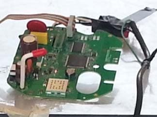
Click to zoom
Application Details
- Equipment Class
- DSS - Part 15 Spread Spectrum Transmitter
- Date of Grant
- Jun 18, 2013
- Application Purpose
- Original Equipment
- Date of Application
- Jun 17, 2013
- Equipment Note
- RFN-430SL
- Frequency Range
- 902.75000000 - 927.25000000
- Company
- Eaton's Cooper Power Systems
- Country
- United States
Documents & Files
Document Text
Text extracted from the exhibit documents filed with the FCC. Open a document above to read the original.
Users Manual
RFN-430SL User’s Guide Document Number XXXX Revision 1 Cooper Power Systems 910 Clopper Road, Suite 201S Gaithersburg, MD 20878 USA www.cooperpowereas.com Tel (301) 515-7118 Fax: (301) 515-4965 XXXXX-01 2 RFN-430SL User’s Guide Contents 1 About the RFN430SL ............................................................................................................................. 3 2 Regulatory Notices................................................................................................................................. 4 3 RFN430SL Specifications ...................................................................................................................... 7 XXXXX-01 3 RFN430SL User’s Guide 1 About the RFN-430SL The RFN-430SL is a radio communications device designed for use in Itron Sentinel meters. It can also be used in Cooper Power Systems Gateways and Relay Nodes. The RFN-430SL provides a 915 MHz radio interface to an RF mesh network. The RFN-430SL operates from a power source of 120 VAC to 480VAC, received from the host device. This voltage is then regulated to 5.0 VDC and 3.3VDC by the on-board power supply circuit. The radio modules operate in license-free bands at 915 MHz (902.75 to 927.25 MHz). RFN-430SL Nodes are fully compatible with mesh network hardware, protocols and operations. Three radio transmission data rates are available: 38.4 kb/s, 76.8 kb/s and153.6 kb/s. The transmission power of the 915 MHz radio is adjustable from 30 dBm to -20 dBm. XXXXX-01 4 RFN-430SL User’s Guide 2 Regulatory Notices Warning The Original Equipment Manufacturer (OEM) must ensure that FCC Labeling requirements are met. This includes a clearly visible label on the outside of the OEM enclosure specifying the Cooper Power Systems FCC identifier (FCC ID: P9X-430SL) and IC Number (IC: 6766A-430SL) as well as the FCC Notice below. Warning This device complies with Part 15 of the FCC Rules. Operation is subject to the following two conditions: (1) This device may not cause harmful interference, and (2) This device must accept any interference received, including interference that may cause undesired operation. Warning Le présent appareil est conforme aux CNR d'Industrie Canada applicables aux appareils radio exempts de licence. L'exploitation est autorisée aux deux conditions suivantes: (1) l'appareil ne doit pas produire de brouillage, et (2) l'utilisateur de l'appareil doit accepter tout brouillage radioélectrique subi, même si le brouillage est susceptible d'en compromettre le fonctionnement. Warning Changes or modifications not expressly approved by the party responsible for compliance could void the user’s authority to operate the equipment. Warning This equipment has been tested and found to comply with the limits for a Class B digital device, pursuant to part 15 of the FCC Rules. These limits are designed to provide reasonable protection against harmful interference in a residential installation. This equipment generates, uses and can radiate radio frequency energy and, if not installed and used in accordance with the instructions, may cause harmful interference to radio communications. However, there is no guarantee that interference will not occur in a particular installation. If this equipment does cause harmful interference to radio or television reception, which can be determined by turning the equipment off and on, the user is encouraged to try to correct the interference by one or more of the following measures: Reorient or relocate the receiving antenna. Increase the separation between the equipment and receiver. Connect the equipment into an outlet on a circuit different from that to which the receiver is connected. Consult the dealer or an experienced radio/TV technician for help. XXXXX-01 5 RFN-430SL User’s Guide Warning The installer of this radio equipment must ensure that the antenna is located or pointed such that it does not emit RF field in excess of Health Canada limits for the general population; consult Safety Code 6, obtainable from Health Canada’s website www.hc-sc.gc.ca/rpb. Warning To comply with FCC RF exposure compliance requirements, the antenna used for this transmitter must be installed to provide a separation distance of at least 20 cm from all persons and must not be co-located or operate in conjunction with any other antenna or transmitter.” As such, the radio component of this device is intended only for OEM integrators under the following two conditions: The antenna must be installed such that 20 cm is maintained between the antenna and users. The transmitter module may not be co-located with any other transmitter or antenna. As long as the two conditions above are met, further transmitter testing will not be required. However, the OEM integrator is still responsible for testing their end product for any additional compliance requirements required with this module installed (e.g., digital device emissions, PC peripheral requirements). In the event that these conditions cannot be met (for example, co-location with another transmitter), then the FCC authorization is no longer considered valid and the FCC ID cannot be used on the final product. In these circumstances, the OEM integrator will be responsible for re-evaluating the end product (including the transmitter) and obtaining a separate FCC authorization. End Product Labeling This transmitter module is authorized only for use in devices where the antenna may be installed such that 20 cm may be maintained between the antenna and users (for example access points, routers, wireless ASDL modems, certain laptop configurations, and similar equipment). The final end product must be labeled in a visible area with the following: “Contains FCC ID: P9X-430SL, IC: 6766A-430SL”. The radio component is an integral part of the RFN-430SL and cannot be removed. XXXXX-01 6 RFN-430SL User’s Guide Warning Transmitters with Detachable Antennas This device has been designed to operate with the antennas l…
Text truncated - open the document above for the full version.
Cover Letter(s)
910 Clopper Road ● Suite 201S ● Gaithersburg, MD 20878 ● Tel. (301) 515 7118 ● Fax (301) 515 4965 ● www.coopereas.com Subject: Modular Approval Request FCC ID: P9X-430SL May 21, 2013 Dear Application Examiner: Cooper Power Systems, model RFN-430SL, FCC ID P9X-430SL, would like to have your authorization as a modular approval. The requirements of Public Notice DA00-1407 have been met and shown on the following statements. 1. "The modular transmitter must have its own RF shielding." - The radio portion of this module has been shielded. Please see exhibition External Photo. 2. "The modular transmitter must have buffered modulation/data inputs." - The RFN-430SL contains buffered data inputs; it is integrated into Cooper Power System's RF design. 3. "The modular transmitter must have its own power supply regulation." - The RFN-430SL contains a regulator in the DC input port; it is integrated into Cooper Power Systems’ RFN-430SL design. 4. "The modular transmitter must comply with the antenna requirements of section 15.203 and 15.204(c)." - The RFN-430SL meets the FCC antenna requirements. The spurious emission, unique antenna connector and photo of antennas are shown in the application exhibits. 5. "The modular transmitter must be tested in a stand-alone configuration." - The RFN-430SL was tested in a stand-alone configuration via an adapter board. Please see exhibit "Test Setup Photos". 6. "The modular transmitter must be labeled with its own FCC ID number." - Please see exhibit "FCC Label" for the FCC to of this module. 7. "The modular transmitter must comply with any specific rule or operating requirements applicable to the transmitter and the manufacturer must provide adequate instructions along with the module to explain any such requirements." - The RFN-430SL is compliant with all applicable FCC rules. Detailed instructions for maintaining compliance are given in the User’s Manual. 8. "The modular transmitter must comply with any applicable RF exposure requirements." - The EUT is compliant with all applicable RF exposure requirements. RF Exposure is addressed in the exhibit "MPE Data". Please contact me if you have any further questions. Thank you for your attention. Sincerely, Steven Seymour Certification Engineer Cooper Power Systems (240) 454-9845 [email protected]
Cover Letter(s)
910 Clopper Road ● Suite 201S ● Gaithersburg, MD 20878 ● Tel. (301) 515 7118 ● Fax (301) 515 4965 ● www.coopereas.com May 21, 2013 Federal Communications Commission Office of Engineering and Technology Equipment Authorization Division 7345 Oakland Mills Road Columbia, MD 21046 RE: Certification Application FCC ID: P9X-430SL We, Cooper Power Systems in Gaithersburg, Maryland, attest that the RFN-430SL is intended to be used only in electric metering products being sold by Cooper Power Systems and its affiliates. It will not be resold to other OEMs or other vendors. Sincerely, Steven Seymour Certification Engineer Cooper Power Systems (240) 454-9845 [email protected]
Cover Letter(s)
910 Clopper Road ● Suite 201S ● Gaithersburg, MD 20878 ● Tel. (301) 515 7118 ● Fax (301) 515 4965 ● www.coopereas.com May 21, 2013 American Certification Body Inc. 6731 Whittier Avenue McLean, VA 22101 To Whom It May Concern: Please be advised that Cooper Power Systems in Gaithersburg, Maryland authorizes Washington Laboratories, Ltd. to act on our behalf, until otherwise notified, for applications submitted to American Certification Body, Inc. (ACB). The following personnel of Washington Laboratories, Ltd. are authorized: Michael F. Violette, President Steven D. Koster, EMC Operations Manager We certify that we are not subject to denial of federal benefits, which includes FCC benefits, pursuant to Section 5301 of the Anti-Drug Abuse ACT of 1988, U.S.C. 862. Further, no party, as defined in 47 CFR 1.2002(b), to the application is subject to denial of federal benefits, that includes FCC benefits. Thank you for your attention to this matter. Sincerely, Steven Seymour Certification Engineer Cooper Power Systems (240) 454-9845 [email protected]
Cover Letter(s)
910 Clopper Road ● Suite 201S ● Gaithersburg, MD 20878 ● Tel. (301) 515 7118 ● Fax (301) 515 4965 ● www.coopereas.com May 21, 2013 Federal Communications Commission Office of Engineering and Technology Equipment Authorization Division 7345 Oakland Mills Road Columbia, MD 21046 RE: Certification Application FCC ID: P9X-430SL Please be advised that under the provision of 47 CFR 0.457 and 0.459 the following exhibits are to be held confidential on behalf of Cooper Power Systems: • Schematics (RFN-430SL Schematic.pdf) • Block diagram (RFN-430SL Block Diagram.pdf) • Theory of Operation/Technical Description (RFN-430SL Circuit Description and Operation.pdf and RFN-430SL Circuit Description and Operation - Appendix.pdf) Rationale for request for confidentiality: Cooper Power Systems wishes to keep these items confidential to maintain a competitive advantage in the marketplace. These items will always be professionally installed. In addition, the device will always be in a controlled, inaccessible environment and are not available to the general public. Sincerely, Steven Seymour Certification Engineer Cooper Power Systems (240) 454-9845 [email protected]
ID Label/Location Info
Cooper Power Systems Photos RFN-430SL (Itron Sentinel) May 21, 2013 4 Figure 4: RFN-430SL – Label Detail
ID Label/Location Info
Cooper Power Systems Photos RFN-430SL (Itron Sentinel) May 21, 2013 1 Figure 1: RFN-430SL - Top
ID Label/Location Info
Cooper Power Systems Labeling Information RFN-430SL (Itron Sentinel) May 21, 2013 1 1. General Information Applicant: Cooper Power Systems Applicant Address: 910 Clopper Road, Suite 201S Gaithersburg, MD 20871 301-515-7118 Product: RFN-430SL (Itron Sentinel) FCC ID: P9X-430SL IC: 6766A-430SL 2. General 2.1. Location The label must be applied to the meter in a place where it will be easily visible. The label should be applied so that all vertical and/or horizontal markings can be read in the same direction as other labels on the meter. 2.2. Markings All human readable markings must be clear and legible when viewed with normal vision at a distance of twelve inches. 2.3. Permanency The label shall not be a stick-on, paper label, and must be permanently affixed to the product. The label must be designed to last the expected lifetime of the equipment in the environment in which the equipment may be operated and must not be readily detachable. 3. Contents of the Label The label must contain the following information: FCC Identifier – the FCC identifier for the RFN-430SL, P9X-430SL IC Number – the Industry Canada certification number for the RFN-430SL, 6766A-430SL Model Number – the model number, RFN-430SL, must appear on the label Manufacturer Name: the name of the manufacturer, Cooper Power Systems, must appear on the label FCC Information – the following statement should appear on the label or in the installation manual: This device complies with part 15 of the FCC Rules. Operation is subject to the following conditions: (1) this device may not cause harmful interference, and (2) this device must accept any interference received including interference that may cause undesired operation. Cooper Power Systems Labeling Information RFN-430SL (Itron Sentinel) May 21, 2013 2 Examples of labels are shown below. The example in Figure 1 shows a label with the required FCC information and both the FCC Identifier and the IC certification number. The example in Figure 2 shows a label with just the FCC Identifier on it and the IC certification number. The required FCC information would appear in the installation manual. Cooper Power Systems, RFN-430SL Contains FCC ID: P9X-430SL / IC: 6766A-430SL This device complies with part 15 of the FCC Rules. Operation is subject to the following conditions: (1) This device may not cause harmful interference. (2) This device must accept any interference received including interference that may cause undesired operation. Figure 1: Label Example with FCC and IC Information Contains FCC ID: P9X-430SL IC: 6766A-430SL Figure 2: Label Example with FCC Information appearing in the installation manual
ID Label/Location Info
Cooper Power Systems Labels RFN-430SL (Itron Sentinel) May 21, 2013 1 A label showing the manufacturer’s name (Cooper Power Systems), the FCC ID (P9X-430SL), and the IC Number (6766A-430SL), and containing the information shown in Figure 1 below, will be affixed to products that incorporate the RFN-430SL, as shown in Figure 2. Cooper Power Systems RFN-430SL Contains FCC ID: P9X-430SL / IC: 6766A-430SL This device complies with part 15 of the FCC Rules. Operation is subject to the following conditions: (1) This device may not cause harmful interference. (2) This device must accept any interference received including interference that may cause undesired operation. Figure 1: External Label Information Figure 2: External Label Location
RF Exposure Info
Certificates and reports shall not be reproduced except in full, without the written permission of Washington Labs, Limited. Maximum Permissible Exposure Evaluation For the Cooper Power Systems RFN-430SL MODULE FCC ID: P9X-430SL IC: 6766A-430SL WLL JOB# 12971-MPE Rev.0 May 6, 2013 Prepared for: COOPER POWER SYSTEMS 20201 CENTURY BLVD. SUITE 250 G ERMANTOWN, MD 20874 Prepared by: WASHINGTON LABORATORIES, LTD. 7560 LINDBERGH DRIVE G AITHERSBURG, MARYLAND 20879 Testing Certificate AT-1448 Cooper Power Systems RFN-430SL RF Exposure Test Report May, 2013 WLL Report #12971-MPE Rev 0 - ii - © 2013 Washington Laboratories, Ltd. Maximum Permissible Exposure Evaluation For the Cooper Power Systems RFN-430SL MODULE FCC ID: P9X-430SL IC: 6766A-430SL WLL JOB# 12971-MPE Rev.0 May 6, 2013 Prepared by: Steven Dovell Compliance Engineer Reviewed by: James Ritter EMC Laboratory Manager Cooper Power Systems RFN-430SL RF Exposure Test Report May, 2013 WLL Report #12971-MPE Rev 0 - iii - © 2013 Washington Laboratories, Ltd. Abstract This report has been prepared on behalf of Cooper Power Systems RFN-430SL to document the findings of the maximum permissible exposure evaluation on the Cooper Power Systems RFN-430SL. The purpose of this evaluation is to establish a minimum safe distance as per the RF exposure requirements as defined in FCC §1.1307, §1.1310, and Industry Canada RSS102 issue 4. This report documents the results of testing to the requirements of: • CFR Title 47 Volume 1 Practice and Procedure; (1.1307) Environmental Assessments The Evaluation was performed by Washington Laboratories, Ltd, 7560 Lindbergh Drive, Gaithersburg, MD 20879. Washington Laboratories, Ltd. has been accepted as an EMC Conformity Assessment Body (CAB) under the United States/European Union Memorandum of Agreement. Washington Laboratories, Ltd. is accredited by ACLASS under Testing Certificate AT-1448. Revision History Reason Date Rev 0 Initial Release May 6 , 2013 Cooper Power Systems RFN-430SL RF Exposure Test Report May, 2013 WLL Report #12971-MPE Rev 0 - iv - © 2013 Washington Laboratories, Ltd. Table of Contents Abstract .................................................................................................................................................................... ii 1 Introduction ................................................................................................................................................ 1 2 Requirements .............................................................................................................................................. 1 2.1 Transmitter Categories ............................................................................................................................. 1 2.2 Exposure Categories ................................................................................................................................ 2 3 Device Summary ......................................................................................................................................... 3 4 Radio Frequency Radiation Exposure Evaluation .................................................................................. 4 4.1 Duty Cycle Corrections ............................................................................................................................ 4 4.2 RF Exposure Results ................................................................................................................................ 4 List of Tables Table 1: MPE Limits ..................................................................................................................................................3 Table 2: Device Summary of the RFN-430SL ...........................................................................................................3 Table 3: Transmitter MPE Calculation Summary ......................................................................................................5 Cooper Power Systems RFN-430SL RF Exposure Test Report May, 2013 WLL Report #12971-MPE Rev 1 - Page 1 of 5 - © 2013 Washington Laboratories, Ltd. 1 Introduction This report has been prepared on behalf of Cooper Power Systems RFN-430SL Transmitter to show compliance with the RF exposure requirements as defined in FCC §1.1307 and IC RSS- 102 issue 4 . Testing supporting this evaluation was performed at Washington Laboratories, Ltd, 7560 Lindbergh Drive, Gaithersburg, MD 20879. Washington Laboratories, Ltd. has been accepted as an EMC Conformity Assessment Body (CAB) under the United States/European Union Memorandum of Agreement. Washington Laboratories, Ltd. is accredited with ACLASS under Testing Certificate AT-1448. 2 Requirements Three different categories of transmitters are defined by the FCC in OET Bulletin 65. These categories are fixed installation, mobile, and portable. Additionally, the FCC categorizes the use of the devices based on the user’s awareness and the ability to exercise control over his or her exposure. The two categories are defined as Occupational/Controlled Exposure and General Population/Uncontrolled Exposure. 2.1 Transmitter Categories 2.1.1 Fixed Installations A fixed location means that the device, including its antenna, is physically secured at a permanent location and is not able to be easily moved to another location. Additionally, distance to humans from the antenna is maintained to at least 2 meters. 2.1.2 Mobile Devices A mobile device is defined as a transmitting device designed to be used in other than fixed locations and to be generally used in such a way that a separation distance of at least 20 centimeters is normally maintained between the transmitter's radiating structures and the body of the user or nearby persons. Transmitters designed to be used by consumers or workers that can be easily re-located, such as a wireless modem operating in a laptop computer, are considered mobile devices if they meet the 20 centimeter sep…
Text truncated - open the document above for the full version.
Test Report
Certificates and reports shall not be reproduced except in full, without the written permission of Washington Laboratories, Limited. FCC & Industry Canada Certification Test Report For the Cooper Power Systems RFN-430SL MODULE FCC ID: P9X-430SL IC: 6766A-430SL WLL JOB# 12971 Rev.1 May 6, 2013 Re-issued June 6, 2013 Prepared for: Cooper Power Systems 910 Clopper Rd. Ste 201S Gaithersburg, MD, 20878 Prepared By: Washington Laboratories, Ltd. 7560 Lindbergh Drive Gaithersburg, Maryland 20879 Testing Certificate AT-1448 Cooper Power Systems RFN-430SL MODULE FCC Certification Test Report May, 2013 WLL Report #12971 Rev.1 - ii - © 2013 Washington Laboratories, Ltd. FCC & Industry Canada Certification Test Report for the Cooper Power Systems RFN-430SL MODULE FCC ID: P9X-430SL IC: 6766A-430SL May 6, 2013 Re-issued June 6, 2013 WLL JOB# 12971 Rev.1 Prepared by: Steven Dovell Compliance Engineer Reviewed by: James Ritter EMC Laboratory Manager Cooper Power Systems RFN-430SL MODULE FCC Certification Test Report May, 2013 WLL Report #12971 Rev.1 - iii - © 2013 Washington Laboratories, Ltd. Abstract This report has been prepared on behalf of Cooper Power Systems to support the attached Application for Equipment Authorization. The test report and application are submitted for a Frequency Hopping Spread Spectrum Transmitter under Part 15.247 (10/2010) of the FCC Rules and Regulations and Spectrum Management and Telecommunications Policy RSS-210 issue 8 of Industry Canada. This Certification Test Report documents the test configuration and test results for the Cooper Power Systems RFN-430SL Module. Testing was performed on an Open Area Test Site (OATS) of Washington Laboratories, Ltd, 7560 Lindbergh Drive, Gaithersburg, MD 20879. Site description and site attenuation data have been placed on file with the FCC's Sampling and Measurements Branch at the FCC laboratory in Columbia, MD. The Industry Canada OATS numbers are 3035A-1 and 3035A-2 for Washington Laboratories, Ltd. Site 1 and Site 2, respectively. Washington Laboratories, Ltd. has been accepted by the FCC and approved by ACLASS under Certificate AT-1448 as an independent FCC test laboratory. The Cooper Power Systems RFN-430SL Module complies with the limits for a Frequency Hopping Spread Spectrum Transmitter device under FCC Part 15.247 and Industry Canada RSS- 210. At the onset of testing the EUT was called the RFN430SN. The name was later changed to RFN430SL, any references shown in plot images to the RFN430SN refer to the RFN430SL. Revision History Description of Change Date Rev 0 Initial Release May 6,2013 Rev 1 Added missing test equipment settings for bandwidth and power measurements. Corrected missing correction factors on radiated spurious and corrected antenna model on 5dBi antenna. June 6, 2013 SD Cooper Power Systems RFN-430SL MODULE FCC Certification Test Report May, 2013 WLL Report #12971 Rev.1 - iv - © 2013 Washington Laboratories, Ltd. Table of Contents Abstract ........................................................................................................................................... ii 1 Introduction ..............................................................................................................1 1.1 Compliance Statement .................................................................................................... 1 1.2 Test Scope ....................................................................................................................... 1 1.3 Contract Information ....................................................................................................... 1 1.4 Test Dates........................................................................................................................ 1 1.5 Test and Support Personnel ............................................................................................ 1 1.6 Abbreviations .................................................................................................................. 2 2 Equipment Under Test .............................................................................................3 2.1 EUT Identification & Description .................................................................................. 3 2.2 Test Configuration .......................................................................................................... 3 2.3 Testing Algorithm ........................................................................................................... 3 2.4 Test Location .................................................................................................................. 4 2.5 Measurements ................................................................................................................. 4 2.5.1 References ................................................................................................................... 4 2.6 Measurement Uncertainty ............................................................................................... 4 3 Test Equipment ........................................................................................................6 4 Test Summary ..........................................................................................................7 5 Test Results ..............................................................................................................8 5.1 Duty Cycle Correction and Time of Occupancy ............................................................. 8 5.2 RF Power Output: (FCC Part §2.1046)......................................................................... 12 5.3 Occupied Bandwidth: (FCC Part §2.1049) ................................................................... 19 5.4 Channel Spacing and Number of Hop Channels (FCC Part §15247(a)(1) ................... 23 5.5 Conducted Spurious Emissions at Antenna Terminals (FCC Part §2.1051) ................ 26 5.5.1 Band Edge Compliance.....…
Text truncated - open the document above for the full version.
Contact Information
Applicant
Steven Seymour(Certification Engineer)
Technical Contact
Washington Laboratories, Ltd.Steven D. Koster
[email protected]301-216-1500
7560 Lindbergh Drive · Gaithersburg, Maryland · United States
Test Firm
Washington Laboratories, Ltd.Steve Koster
Technical Specifications
| # | Rule Parts | Frequency Range | Power Output |
|---|---|---|---|
| 1 | 15C | 902.75 MHz - 927.25 MHz | 955.00 mW |
Other Applications from Eaton's Cooper Power Systems
P9X-410CL
Jul 16, 2013RFN-410CL
Equipment Class
DSS - Part 15 Spread Spectrum Transmitter
P9X-420CL1WNZ
Jan 09, 2013RFN 420CL(1W, NZ) Module
Equipment Class
DSS - Part 15 Spread Spectrum Transmitter
P9X-420CL1W
Jan 09, 2013Utility Meter Reading Transmitter
Equipment Class
DSS - Part 15 Spread Spectrum Transmitter
P9X-430ELA31W
Nov 25, 2012RFN 430EL-A3 (1W)
Equipment Class
DSS - Part 15 Spread Spectrum Transmitter
P9X-RFNSCOMMMRB
Apr 17, 2012RFN SelectComm-MRB Module
Equipment Class
DSS - Part 15 Spread Spectrum Transmitter