PB8P4432-052Point of Sale Terminal
Thales e- Transactions S.A.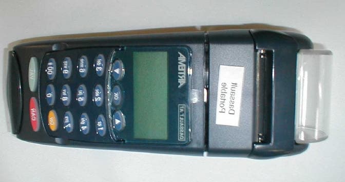
Click to zoom
Application Details
- Equipment Class
- DSS - Part 15 Spread Spectrum Transmitter
- Date of Grant
- Sep 24, 2001
- Application Purpose
- Original Equipment
- Date of Application
- Apr 18, 2001
- Equipment Note
- Point of Sale Terminal
- Frequency Range
- 903.80000000 - 911.20000000
- Company
- Thales e- Transactions S.A.
- Country
- France
Documents & Files
Document Text
Text extracted from the exhibit documents filed with the FCC. Open a document above to read the original.
Cover Letter(s)
Monday, August 20, 2001 To:Joe Dichoso [email protected] FCC Application Processing Branch From:Gregory Snyder, Washington Laboratories, Ltd. Re:FCC ID PB8P4432-052 Applicant:Dassault Automatismes & Telecommunications Correspondence Reference Number:19468 731 Confirmation Number:EA100701 Following are the questions raised by the FCC review of the above referenced application. Each question has been answered (see italicized text) and, where appropriate, new exhibits have been uploaded. 1) Block diagram showing all frequencies and oscillators. A new block diagram of the Stamptronics FHSS radio block has been uploaded. File: “Stamptronics Block Diagram.pdf” 2) The technical description indicates that the transmitter synchronizes with multiple transmitters. This does not appear to comply with Section 15.247(h). Please explain. The transmitter cannot coordinate its hopping sequence with the hopping sequence of other transmitters, or vice versa, for the purpose of avoiding the simultaneous occupancy of individual hopping frequencies by multiple transmitters. Once the radios have been configured and completed the “acquisition procedure”, the radios in the network operate completely independently of any other radios in the local area. Eight different hopping tables are available for each network, and this provides an additional method to minimize collisions between networks. 3) The technical description indicates an output power of 12 dBm 2 dB for at total of 14 dB. You measusred only 10.67 dBm. Please explain. Correct/supply any data or exhibits. The RF safety calculations must use the appropriate output power. The unit should be listed as 10.67dBm maximum power as measured. The new “Description of Transmission” document (“Artema FHSS Description.pdf”) has been updated to reflect this. 4) Indicate the antenna and antenna gain, and antenna location to justify the 1.5 cm distance RF separation distance. The antenna is a unipole, quarter wave type and the gain is lower than 0dBi. A drawing of the antenna, Model 4432-601A501, has been uploaded as “Artema FHSS Antenna.pdf”. Also, the distance from the antenna to the outside of the case is approximately 0.5cm. Since this distance does not provide the necessary calculated distance, Power spectral density measurements were performed around the unit near the antenna and in all directions and the highest recorded levels for each 3 channels tested were: Channel Measured Level Limit Channel 0, 903.8MHz:0.169mW/cm 2 0.61mW/cm 2 Channel 24, 907.4MHz:0.155mW/cm 2 0.61mW/cm 2 Channel 49, 911.15MHz:0.141mW/cm 2 0.61mW/cm 2 5) The pseudorandom sequence provided was for test purposes only. Provide samples of the actual sequence and indicate how they are derived. The pseudorandom sequences are described on page 6 of the new “Description of Transmission” (see Channel Table). What is called "Table 0" is actually a feature used only for test purposes. The operational tables (Table 1, 2 & 3) are pseudorandom. The 8 pseudorandom hopping tables are burned into the EEPROM memory, and do not change. All 8 tables have the following characteristics: they use each channel only once per 50 hops, and they move randomly both in direction and in number of channels hopped. They were derived with the following procedure: The three tables were created with an algorithm based on the RANDOM() function, with rejection of frequencies already used. 6) Each frequency must be used equally on the average by each transmitter. Except for voice systems, each new transmission must start at a different point in the sequence so that on average the full sequence is used. Therefore, Describe where the next transmission starts when all frequencies are not used for a previous message. This is required because some transmissions may need only a few frequency hops to be completed. i.e. If the transmission started on the same frequency each time, this frequency would be used more than the others if many short transmissions were sent. The next transmission starts with the next channel in the hopping table sequence. For example, if a short transmission starts with the first channel in the hopping table and needs only 8 hops to complete the transmission, the next transmission will start with the ninth channel in the hopping table sequence. 7) Section 15.247(a)1 indicates that the system receivers shall have input bandwidths that match the hopping channel bandwidths of their corresponding transmitters and shall shift frequencies in synchronization with the transmitted signals. Please explain how the device complies with this rule when a packet is repeated or when multiple packets are sent. What is the receiver input bandwidth? How does the receiver shift frequencies and determine which frequency to shift to in order to synchronize with this transmitter? The receiver uses a VCO to rapidly shift frequencies in synchronization with the transmitted signals, based on the hopping table that was chosen during the acquisition procedure. When a packet is repeated, it is transmitted on the next hopping channel, which is a different frequency. The receiver input bandwidth is limited by the filters on the receiver, which have a passband of +/- 50kHz at 3 dB. The adjacent channel rejection is 20dB The receiver shifts frequencies with the following procedure: After changing to a new hopping frequency, the microcontroller sends a command to the VCO to shift frequencies. It waits until the VCO has stabilized, then activates the receiver chip, and starts to process the data from the received signals.
Cover Letter(s)
Wednesday, September 5, 2001 To: Joe Dichoso [email protected] FCC Application Processing Branch From: Gregory Snyder, Washington Laboratories, Ltd. Re: FCC ID PB8P4432-052 Applicant: Dassault Automatismes & Telecommunications Correspondence Reference Number: 20463 731 Confirmation Number: EA100701 Following are the questions raised by the FCC review of the above referenced application. Each question has been answered (see italicized text) and, where appropriate, new exhibits have been uploaded. 1) In the Acquisition procedure, it appears that the remotest synchronize with the base. The base sends them synchronization information. The base is coordinating with multiple remotest to avoid interference. The remotest end up all synchronized with each other. This is not allowed. Please correct or the application will be denied. Ans: Each network ** has its own synchronization (clock, time slots, slot sequence (table) ...). The server of one network can only communicate with its clients. A server cannot communicate with another server. It is impossible for two networks (or systems) to be synchronized with each other : they are independent from each another. Nothing is done to avoid collisions. If, by chance, two networks disturb each other because they use the same channel in one given time slot, on the next time slot, they will be on different channels (because they don't have the same synchronization) and therefore won't disturb each other. ** one network = one master (server) and up to 4 slaves (clients) In our application, the server is the base unit, the clients are the hand held terminals 2) The pseudorandom sequence is not pseudorandom. The examples show that the hop sequence hops to the next channel that is 10, 12, or 13 channels above the last channel. Section 2.1 indicates that the sequential hops must be randomly distributed in both direction and magnitude of change in the hop set. The hop set submitted has the same direction and magnitude. This is not allowed. Please correct or the application will be denied. Ans: A new hop sequence table has been inserted in the new revision of FHSS Description. 3) The output power on page 6 of the new FHSS description was not corrected to 10.67 dBm. Ans: The output power has been corrected on page 6 and a new FHSS Description has been uploaded.
Cover Letter(s)
Wednesday, September 5, 2001 To: Joe Dichoso [email protected] FCC Application Processing Branch From: Gregory Snyder, Washington Laboratories, Ltd. Re: FCC ID PB8P4432-052 Applicant: Dassault Automatismes & Telecommunications Correspondence Reference Number: 20463 731 Confirmation Number: EA100701 Following are the questions raised by the FCC review of the above referenced application. Each question has been answered (see italicized text) and, where appropriate, new exhibits have been uploaded. In the Acquisition procedure, it appears that the remotest synchronize with the base. The base sends them synchronization information. The base is coordinating with multiple remotest to avoid interference. The remotest end up all synchronized with each other. This is not allowed. Please correct or the application will be denied. Ans: Each network ** has its own synchronization (clock, time slots, slot sequence (table) ...). The server of one network can only communicate with its clients. A server cannot communicate with another server. It is impossible for two networks (or systems) to be synchronized with each other : they are independent from each another. Nothing is done to avoid collisions. If, by chance, two networks disturb each other because they use the same channel in one given time slot, on the next time slot, they will be on different channels (because they don't have the same synchronization) and therefore won't disturb each other. ** one network = one master (server) and up to 4 slaves (clients) In our application, the server is the base unit, the clients are the hand held terminals 1) The pseudorandom sequence is not pseudorandom. The examples show that the hop sequence hops to the next channel that is 10, 12, or 13 channels above the last channel. Section 2.1 indicates that the sequential hops must be randomly distributed in both direction and magnitude of change in the hop set. The hop set submitted has the same direction and magnitude. This is not allowed. Please correct or the application will be denied. Ans: A new hop sequence table has been inserted in the new revision of FHSS Description. The output power on page 6 of the new FHSS description was not corrected to 10.67 dBm. Ans: The output power has been corrected on page 6 and a new FHSS Description has been uploaded.
External Photos
Front Side Side Bottom
ID Label/Location Info
P4432-052 FCC ID: PB8P4432-052 *4432052XXXXX*
Internal Photos
Front Cover Removed Keypad Removed Upper PCB Top Upper PCB Bottom Bottom - Battery Removed Battery Shield Removed Back Cover Removed Bottom with RF Module Removed Lower PCB Top Lower PCB Bottom RF Module PCB Top RF Module PCB Shield Removed RF Module PCB Bottom
Operational Description
THIS DOCUMENT IS PROPERTY THE OF DASSAULT A. T. AND MAY NOT BE COPIED OR RELEASED WITHOUT WRITTEN CONSENT. ARTEMA 900 MHZ FHSS RADIO REF. P4432-150 (BASE UNIT) P4432-050 & -052 (HAND HELD UNIT) DESCRIPTION OF TRANSMISSION ____________ DASSAULT AT AUTOMATISMES & TELECOMMUNICATIONS Reference : NE 333 043 Revision : 1.1 Date : 25/07/01 Status : REFERENCE Distribution : CONFIDENTIAL ARTEMA 900 MHz FHSS Radio DESCRIPTION OF TRANSMISSION THIS DOCUMENT IS PROPERTY THE OF DASSAULT A. T. AND MAY NOT BE COPIED OR RELEASED WITHOUT WRITTEN CONSENT. DASSAULT A.T. Writer Approval Control Bernard Meuriche Olivier POITRENAUD Gérard LECUYER Archive ARTEMA Revisions Indice Date Objet 1.0 25/04/00 Création du document 1.1 25/07/01 Answers to FCC questions ARTEMA 900 MHz FHSS Radio DESCRIPTION OF TRANSMISSION page 1 THIS DOCUMENT IS PROPERTY THE OF DASSAULT A. T. AND MAY NOT BE COPIED OR RELEASED WITHOUT WRITTEN CONSENT. DASSAULT A.T. DESCRIPTION OF TRANSMISSION The radio module RFM 900 FHSS is a 900MHz FCC 15.247 frequency hopping transceiver. At baseband end, the interface of the radio module is a serial link. At the antenna interface the radio is working between 903.8 and 911.15 MHz using frequency hopping. The frequency hopping : There are 50 frequencies numbered from 0 to 49 spaced by 150 kHz, that is to say : 903.8 CH. 0 center frequency 903.95 CH 1 " 907.4 CH 24 " 911.15 CH 49 " These frequencies are arranged randomly in up to 3 different tables which are stocked in the software. Each dwell timer the transmission occurs on a different channel, following the order defined by the table at both ends synchronously ARTEMA 900 MHz FHSS Radio DESCRIPTION OF TRANSMISSION page 2 THIS DOCUMENT IS PROPERTY THE OF DASSAULT A. T. AND MAY NOT BE COPIED OR RELEASED WITHOUT WRITTEN CONSENT. DASSAULT A.T. The dwell timer Dwell timer 6 slots Reservation grant data ACK The dwell timer is divided in several parts : - Reservation in which up to 6 mobiles may send a reservation burst in order to get a grant from the base station. The base station may however keep the current dwell timer for itself, not granting to any mobile. - Depending of the decision of the base, based on a priority scheme, the mobile (or base) that was designated by the grant is allowed to transmit a data packet during the current dwell timer. Data is protected by a CRC. - The data is transmitted during the data phase of the dwell timer using FSK modulation. Two bits are associated to code a baseband – tone frequency among four tones (18/22/28/40 kHz). Each tone, during the dual bit duration modulates the frequency of the transmit oscillator. - The last phase of the dwell timer is the ACK which is sent if the receive side has a correct CRC checksum. dwell time : 92 ms reservation slot : 4 ms / 6ms reservation: 36 ms grant : 7 ms data+ carrier = data : 64 char. max +10 19+ 5 ms =24ms ACK : 7ms ARTEMA 900 MHz FHSS Radio DESCRIPTION OF TRANSMISSION page 3 THIS DOCUMENT IS PROPERTY THE OF DASSAULT A. T. AND MAY NOT BE COPIED OR RELEASED WITHOUT WRITTEN CONSENT. DASSAULT A.T. Prioritization scheme The priority algorithm attempts to share the frequency equally between the links. More specifically at each grant the base gives the link to - the various mobile in ascending order - itself if it has not just transmitted and needs to do it. Examples : 1. – B M1 B M2 B M3 B M4 B M5 B M6 B.... only if the base has something to transmit at that time. (the base has many things to transmit) 2 - B M1 M2 M3 M4 M5 M6 B (the base has few things to transmit) 3 - M1 M4 M5 M1 M4 M5 (only M1 M4 and M5 have something to transmit) 4 - M1 M1 M1 M1 (only M1 has something to transmit) Synchronization On two frequencies (selected by software for one network), the base transmits a synchronization burst on which each mobile may synchronize to the frequency table. At the beginning, the mobile settles on a synchronization frequency alternatively and looks for the synchronization burst. When found, the mobile follows the frequency table in synchronization with the base. The channel access is done by transmitting a reservation slot in the reservation phase. ARTEMA 900 MHz FHSS Radio DESCRIPTION OF TRANSMISSION page 4 THIS DOCUMENT IS PROPERTY THE OF DASSAULT A. T. AND MAY NOT BE COPIED OR RELEASED WITHOUT WRITTEN CONSENT. DASSAULT A.T. Radiated Power density Ô = Pe Ge 4Ïd² d min = 5 mm between antenna wire and outside of the base or hand held unit P max = 10.67 dBm = 11.7mw (Hand-Held Unit) G 0 dBi Ô 11.7 mw = 3.72mw/cm² 4 x Ï (0.5)² P max = 12.33 dBm = 17.1mw (Base Unit) G 0 dBi Ô 17.1 mw = 5.44mw/cm² 4 x Ï (0.5)² ARTEMA 900 MHz FHSS Radio DESCRIPTION OF TRANSMISSION page 5 THIS DOCUMENT IS PROPERTY THE OF DASSAULT A. T. AND MAY NOT BE COPIED OR RELEASED WITHOUT WRITTEN CONSENT. DASSAULT A.T. Radio block diagram See block diagram in attachments Output Rx power : 12 ± 2 dBm Sensitivity Rx : - 85 dBm @ 10 ̄³ BER Antenna gain ~ 0 dBi Overall block diagram Ø PSTN Main AC To mobile Radio module ìP Modem Power supply AC/DC ARTEMA 900 MHz FHSS Radio DESCRIPTION OF TRANSMISSION page 6 THIS DOCUMENT IS PROPERTY THE OF DASSAULT A. T. AND MAY NOT BE COPIED OR RELEASED WITHOUT WRITTEN CONSENT. DASSAULT A.T. Channels Slot N° Table 1 Table 2 Table 3 1 2 2 2 2 12 15 18 3 22 28 34 4 32 41 3 5 42 1 19 6 3 14 35 7 13 27 4 8 23 40 20 9 33 13 36 10 43 26 5 11 4 39 21 12 14 12 37 13 24 25 6 14 34 38 22 15 44 0 38 16 5 11 7 17 15 24 23 18 25 37 39 19 35 10 8 20 45 23 24 21 6 36 40 22 16 49 9 23 26 9 25 24 36 22 41 25 46 35 10 26 7 48 26 27 17 8 42 28 27 21 0 29 37 34 11 30 47 47 27 31 8 7 43 32 18 20 12 33 28 33 28 34 38 46 44 35 48 6 13 36 9 19 29 37 19 32 45 38 29 45 14 39 39 5 30 40 49 18 46 41 0 31 15 42 10 44 31 43 20 4 47 44 30 17 16 45 40 30 32 46 1 43 48 47 11 3 1 48 21 16 17 49 31 29 33 50 41 42 49 Table 0 = always the same channel (test purpose only) ARTEMA 900 MHz FHSS Radio DESCRIPTION OF TRANSMISSION page 7 THIS DOCUMENT IS PROPERTY THE OF DASSAULT A. T. AND MAY NOT BE COPIED OR RELEASED…
Text truncated - open the document above for the full version.
Operational Description
THIS DOCUMENT IS PROPERTY THE OF DASSAULT A. T. AND MAY NOT BE COPIED OR RELEASED WITHOUT WRITTEN CONSENT. ARTEMA 900 MHZ FHSS RADIO REF. P4432-150 (BASE UNIT) P4432-050 & -052 (HAND HELD UNIT) DESCRIPTION OF TRANSMISSION ____________ DASSAULT AT AUTOMATISMES & TELECOMMUNICATIONS Reference : NE 333 043 Revision : 1.2 Date : 04/09/01 Status : REFERENCE Distribution : CONFIDENTIAL ARTEMA 900 MHz FHSS Radio DESCRIPTION OF TRANSMISSION THIS DOCUMENT IS PROPERTY THE OF DASSAULT A. T. AND MAY NOT BE COPIED OR RELEASED WITHOUT WRITTEN CONSENT. DASSAULT A.T. Writer Approval Control Bernard Meuriche Olivier POITRENAUD Gérard LECUYER Archive ARTEMA Revisions Indice Date Objet 1.0 25/04/00 Création du document 1.2 25/07/01 Answers to FCC questions 1.2 04/09/01 Answers to additional FCC questions ARTEMA 900 MHz FHSS Radio DESCRIPTION OF TRANSMISSION page 1 THIS DOCUMENT IS PROPERTY THE OF DASSAULT A. T. AND MAY NOT BE COPIED OR RELEASED WITHOUT WRITTEN CONSENT. DASSAULT A.T. DESCRIPTION OF TRANSMISSION The radio module RFM 900 FHSS is a 900MHz FCC 15.247 frequency hopping transceiver. At baseband end, the interface of the radio module is a serial link. At the antenna interface the radio is working between 903.8 and 911.15 MHz using frequency hopping. The frequency hopping : There are 50 frequencies numbered from 0 to 49 spaced by 150 kHz, that is to say : 903.8 CH. 0 center frequency 903.95 CH 1 " 907.4 CH 24 " 911.15 CH 49 " These frequencies are arranged randomly in up to 3 different tables which are stocked in the software. Each dwell timer the transmission occurs on a different channel, following the order defined by the table at both ends synchronously ARTEMA 900 MHz FHSS Radio DESCRIPTION OF TRANSMISSION page 2 THIS DOCUMENT IS PROPERTY THE OF DASSAULT A. T. AND MAY NOT BE COPIED OR RELEASED WITHOUT WRITTEN CONSENT. DASSAULT A.T. The dwell timer Dwell timer 6 slots Reservation grant data ACK The dwell timer is divided in several parts : - Reservation in which up to 6 mobiles may send a reservation burst in order to get a grant from the base station. The base station may however keep the current dwell timer for itself, not granting to any mobile. - Depending of the decision of the base, based on a priority scheme, the mobile (or base) that was designated by the grant is allowed to transmit a data packet during the current dwell timer. Data is protected by a CRC. - The data is transmitted during the data phase of the dwell timer using FSK modulation. Two bits are associated to code a baseband – tone frequency among four tones (18/22/28/40 kHz). Each tone, during the dual bit duration modulates the frequency of the transmit oscillator. - The last phase of the dwell timer is the ACK which is sent if the receive side has a correct CRC checksum. dwell time : 92 ms reservation slot : 4 ms / 6ms reservation: 36 ms grant : 7 ms data+ carrier = data : 64 char. max +10 19+ 5 ms =24ms ACK : 7ms ARTEMA 900 MHz FHSS Radio DESCRIPTION OF TRANSMISSION page 3 THIS DOCUMENT IS PROPERTY THE OF DASSAULT A. T. AND MAY NOT BE COPIED OR RELEASED WITHOUT WRITTEN CONSENT. DASSAULT A.T. Prioritization scheme The priority algorithm attempts to share the frequency equally between the links. More specifically at each grant the base gives the link to - the various mobile in ascending order - itself if it has not just transmitted and needs to do it. Examples : 1. – B M1 B M2 B M3 B M4 B M5 B M6 B.... only if the base has something to transmit at that time. (the base has many things to transmit) 2 - B M1 M2 M3 M4 M5 M6 B (the base has few things to transmit) 3 - M1 M4 M5 M1 M4 M5 (only M1 M4 and M5 have something to transmit) 4 - M1 M1 M1 M1 (only M1 has something to transmit) Synchronization On two frequencies (selected by software for one network), the base transmits a synchronization burst on which each mobile may synchronize to the frequency table. At the beginning, the mobile settles on a synchronization frequency alternatively and looks for the synchronization burst. When found, the mobile follows the frequency table in synchronization with the base. The channel access is done by transmitting a reservation slot in the reservation phase. ARTEMA 900 MHz FHSS Radio DESCRIPTION OF TRANSMISSION page 4 THIS DOCUMENT IS PROPERTY THE OF DASSAULT A. T. AND MAY NOT BE COPIED OR RELEASED WITHOUT WRITTEN CONSENT. DASSAULT A.T. Radiated Power density Ô = Pe Ge 4Ïd² d min = 5 mm between antenna wire and outside of the base or hand held unit P max = 10.67 dBm = 11.7mw (Hand-Held Unit, P4432-050 & -052) G 0 dBi Ô 11.7 mw = 3.72mw/cm² 4 x Ï (0.5)² P max = 12.33 dBm = 17.1mw (Base Unit, P4432-150) G 0 dBi Ô 17.1 mw = 5.44mw/cm² 4 x Ï (0.5)² ARTEMA 900 MHz FHSS Radio DESCRIPTION OF TRANSMISSION page 5 THIS DOCUMENT IS PROPERTY THE OF DASSAULT A. T. AND MAY NOT BE COPIED OR RELEASED WITHOUT WRITTEN CONSENT. DASSAULT A.T. Radio block diagram See block diagram in attachments Output power : 10.67dBm (Hand-Held Unit), 12.33dBm (Base Unit) Sensitivity Rx : - 85 dBm @ 10 ̄³ BER Antenna gain ~ 0 dBi Overall block diagram Ø PSTN Main AC To mobile Radio module ìP Modem Power supply AC/DC ARTEMA 900 MHz FHSS Radio DESCRIPTION OF TRANSMISSION page 6 THIS DOCUMENT IS PROPERTY THE OF DASSAULT A. T. AND MAY NOT BE COPIED OR RELEASED WITHOUT WRITTEN CONSENT. DASSAULT A.T. Channels N.B. : table 0 is not used currently (except for tests) and is always on the same channel given by register S202 CONFIDENTIEL Tables des Canaux B900SS-20 Table 1Table 2Table 3Table 4Table 5Table 6Table 7Table 8 163114247394244 23482718243198 3032403448494111 37139391810536 44226233523817 041372540477 498333011349 421616193226241 353329354647747 283424020161614 216384734143243 141225221917818 72412201692710 5490361043345 123411284432520 19524442345462 2610373842411929 33204930012260 4041361341304930 471923831372246 45391068443621 381544146103 313017928231322 2440302527241728 31743411581437 173548512254319 10735212120139 11422373646227 8289242229354 1502101424840 2236152…
Text truncated - open the document above for the full version.
Test Report
FCC CERTIFICATION TEST REPORT for Dassault AT 9, rue Elsa Triolet 78373 PLAISIR cedex France FCC ID: PB8P4432-050 January 26, 2001 WLL PROJECT #: 5569X This report may not be reproduced, except in full, without the prior written consent of Washington Laboratories, Ltd. Dassault A.T. FCC ID:PB8P4432-050 WLL Project #:5569X i TABLE OF CONTENTS Statement of Qualifications 1.0INTRODUCTION............................................................................................................................................. 2 1.1S UMMARY ........................................................................................................................................................ 2 2.0DESCRIPTION OF EQUIPMENT UNDER TEST (EUT) ............................................................... 2 3.0TEST CONFIGURATION...............................................................................................................................3 3.1T ESTIN G A LGO RITHM ....................................................................................................................................... 3 3.2R ADIATED E MISSIONS T ESTIN G ........................................................................................................................ 3 3.2.1Radiated Data Reduction and Reporting .............................................................................................. 3 Tables Table 1.Radiated Emissions Results Table 2.Spurious Radiated Emissions (20 dBc) Table 3.System Under Test Table 4.Interface Cables Used Table 5.Measurement Equipment Used Exhibits Exhibit 2.Bandwidth Plots Appendices Appendix A.Statement of Measurement Uncertainty Dassault A.T. FCC ID:PB8P4432-050 WLL Project #:5569X 1 Dassault A.T. FCC ID:PB8P4432-050 WLL Project #:5569X 2 FCC CERTIFICATION TEST REPORT for FCC ID: PB8P4432-050 1.0Introduction This report has been prepared on behalf of Dassault A.T. to support the attached Application for Equipment Authorization. The test and application are submitted for a Frequency Hopping Spread Spectrum Transmitter under Part 15.247 of the FCC Rules and Regulations. The Equipment Under Test was the Dassault A.T. ARTEM A US Portable EFT/POS Radio, M/N: P4432-050 and P4432-052 All measurements herein were performed according to the 1992 version of ANSI C63.4. The measurement equipment conforms to ANSI C63.2 Specifications for Electromagnetic Noise and Field Strength Instrumentation. Calibration checks are made periodically to verify proper performance of the measuring instrumentation. All measurements are performed at Washington Laboratories, Ltd. test center in Gaithersburg, MD. Site description and site attenuation data have been placed on file with the FCC's Sampling and Measurements Branch at the FCC laboratory in Columbia, MD. Washington Laboratories, Ltd. has been accepted by the FCC and approved by NIST NVLAP (NVLAP Lab Code: 200066-0) as an independent FCC test laboratory. All results reported herein relate only to the equipment tested. The measurement uncertainty of the data contained herein is ± 2.3 dB. Refer to Appendix A for Statement of Measurement Uncertainty. This report shall not be used to claim product endorsement by NVLAP or any agency of the US Government. 1.1Summary The Dassault A.T. ARTEMA US Portable EFT/POS Radio complies with the requirements for a Frequency Hopping Spread Spectrum Transmitter under Part 15.247 of the FCC Rules and Regulations. 2.0Description of Equipment Under Test (EUT) The Dassault A.T. ARTEMA US Portable EFT/POS Transmitter (EUT) is a portable hand-held, battery-powered Electronic Fund Transfer/Point of Sale terminal. The radio is a Frequency Hopping Spread Spectrum transmitter operating in the 902 – 928 MHz frequency band. The EUT incorporates a 17 key keypad, magnetic card reader, removable/re-chargeable battery pack, and a printer. The two hand-held terminal models: P4432-050 and P4432-052 are identical except that the –052 has secured keyboard circuitry. Both the P4432-050 and P4432-052 ARTEM A US Portables are marketed with two different Base Chargers (M/N: P4432-160 and P4432-150). The model P4432-150 Base Charger contains a separate FHSS radio and telecom ports for use w ith communicating to the hand-held. The P4432-150 unit will be submitted as a separate FCC application. Dassault A.T. FCC ID:PB8P4432-050 WLL Project #:5569X 3 3.0Test Configuration To complete the test configuration required by the FCC, the transmitter was tested in all three orthogonal planes. The unit is a self-contained unit with no I/O ports. 3.1Testing Algorithm The transmitter was configured to continuously transmit during testing. The unit was fixed (hopping disabled) to the Low Channel, Middle Channel and High Channel during the emissions testing. The system w as tested in all three orthogonal planes. The unit was also tested while being placed on the charger base, however, worst case emissions were obtained while the unit was in standalone operation. Worst case emissions are recorded in the data tables. 3.2Radiated Emissions Testing The EUT was placed on an 80 cm high 1 x 1.5 meters non-conductive motorized turntable for radiated testing on a 3 meter open field test site. The emissions from the EUT w ere measured continuously at every azimuth by rotating the turntable. Biconical and log periodic broadband antennas were mounted on an antenna mast to determine the height of maximum emissions. The height of the antenna was varied between 1 and 4 meters. The peripherals were placed on the table in accordance with ANSI C63.4-1992. Cables were varied in position to produce maximum emissions. Both the horizontal and vertical field components were measured. The output from the antenna was connected, via a preamplifier, to the input of the spectrum analyzer. The detector function was set to quasi-peak or peak, as appropriate. The measurement bandwidth on the spectrum analyzer system was set to at least 120 kHz, with all post-detector …
Text truncated - open the document above for the full version.
Test Setup Photos
Radiated Emissions Test Setup – Front View Radiated Emissions Test Setup – Back View
Contact Information
Applicant
Olivier Poitrenaud(R & D Engineer)
Technical Contact
Washington Laboratories, Ltd.Gregory M Snyder
[email protected]301/ 417-0220
7560 Lindbergh Drive · Gaithersburg, Maryland · United States
Non-Technical Contact
Washington Laboratories, Ltd.Brian J Dettling
[email protected]301/ 417-0220
Test Firm
Washington Laboratories, Ltd.Michael Violette
Technical Specifications
| # | Rule Parts | Frequency Range | Power Output |
|---|---|---|---|
| 1 | 15C | 903.8 MHz - 911.2 MHz | 11.70 mW |
Other Applications from Thales e- Transactions S.A.

PB8P4432-150
Sep 23, 2001Point of Sale Terminal
Equipment Class
DSS - Part 15 Spread Spectrum Transmitter
PB8P4432-051
Mar 28, 2001Point of Sale Terminal
Equipment Class
TNB - Licensed Non-Broadcast Station Transmitter