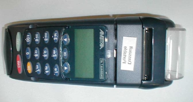
PB8P4432-150Point of Sale Terminal
Thales e- Transactions S.A.
Click to zoom
Application Details
- Equipment Class
- DSS - Part 15 Spread Spectrum Transmitter
- Date of Grant
- Sep 23, 2001
- Application Purpose
- Original Equipment
- Date of Application
- Apr 18, 2001
- Equipment Note
- Point of Sale Terminal
- Frequency Range
- 903.80000000 - 911.20000000
- Company
- Thales e- Transactions S.A.
- Country
- France
Documents & Files
Document Text
Text extracted from the exhibit documents filed with the FCC. Open a document above to read the original.
Cover Letter(s)
Monday, August 20, 2001 To: Joe Dichoso [email protected] FCC Application Processing Branch From: Gregory Snyder, Washington Laboratories, Ltd. Re: FCC ID PB8P4432-150 Applicant: Dassault Automatismes & Telecommunications Correspondence Reference Number: 19470 731 Confirmation Number: EA100704 Following are the questions raised by the FCC review of the above referenced application. Each question has been answered (see italicized text) and, where appropriate, new exhibits have been uploaded. 1) Block diagram showing all frequencies and oscillators. A new block diagram of the Stamptronics FHSS radio block has been uploaded. File: “Stamptronics Block Diagram.pdf” 2) Provide the technical description for the base unit. The technical description supplied is for the portable unit. The pseudorandom sequence appeared to not comply. It did not meet the definition in Section 2.1 for FHSS systems. You may want to go ahead and also indicate how the device complies with the non-coordination requirement requested in the previous application. A new “Description of Transmission” document (“Artema FHSS Description.pdf”) has been uploaded which includes both the hand-held and base units. The pseudorandom sequences are described on page 6 of the new “Description of Transmission” (see Channel Table). What is called "Table 0" is actually a feature used only for test purposes. The operational tables (Table 1, 2 & 3) are pseudorandom. 3) Indicate the antenna and antenna gain, and antenna location to justify the 1.5 cm distance RF separation distance. The antenna is a unipole, quarter wave type and the gain is lower than 0dBi. A drawing of the antenna, Model 4432-601A502, has been uploaded as “Artema FHSS Antenna.pdf”. Also, the distance from the antenna to the outside of the case is approximately 0.5cm. Since this distance does not provide the necessary calculated minimum distance, Power spectral density measurements were performed around the unit near the antenna and in all directions and the highest recorded levels for each 3 channels tested were: Channel Measured Level Limit Channel 0, 903.8MHz:0.186mW/cm 2 0.61mW/cm 2 Channel 24, 907.4MHz:0.173mW/cm 2 0.61mW/cm 2 Channel 49, 911.15MHz:0.164mW/cm 2 0.61mW/cm 2 All measured levels are well within the Power Spectral Density limits for exposure. 4) Each frequency must be used equally on the average by each transmitter. Except for voice systems, each new transmission must start at a different point in the sequence so that on average the full sequence is used. Therefore, Describe where the next transmission starts when all frequencies are not used for a previous message. This is required because some transmissions may need only a few frequency hops to be completed. i.e. If the transmission started on the same frequency each time, this frequency would be used more than the others if many short transmissions were sent. The next transmission starts with the next channel in the hopping table sequence. For example, if a short transmission starts with the first channel in the hopping table and needs only 8 hops to complete the transmission, the next transmission will start with the ninth channel in the hopping table sequence. 5) Section 15.247(a)1 indicates that the system receivers shall have input bandwidths that match the hopping channel bandwidths of their corresponding transmitters and shall shift frequencies in synchronization with the transmitted signals. Please explain how the device complies with this rule when a packet is repeated or when multiple packets are sent. What is the receiver input bandwidth? How does the receiver shift frequencies and determine which frequency to shift to in order to synchronize with this transmitter? The receiver uses a VCO to rapidly shift frequencies in synchronization with the transmitted signals, based on the hopping table that was chosen during the acquisition procedure. When a packet is repeated , it is transmitted on the next hopping channel, which is a different frequency. The receiver input bandwidth is limited by the filters on the receiver, which have a passband of +/- 50kHz at 3 dB. The adjacent channel rejection is 20dB The receiver shifts frequencies with the following procedure: After changing to a new hopping frequency, the microcontroller sends a command to the VCO to shift frequencies. It waits until the VCO has stabilized, then activates the receiver chip, and starts to process the data from the received signals. 6) External photo's External photo exhibit (“External Photos.pdf”) has been uploaded.
Cover Letter(s)
Wednesday, September 5, 2001 To: Joe Dichoso [email protected] FCC Application Processing Branch From: Gregory Snyder, Washington Laboratories, Ltd. Re: FCC ID PB8P4432-150 Applicant: Dassault Automatismes & Telecommunications Correspondence Reference Number: 20465 731 Confirmation Number: EA100704 Following are the questions raised by the FCC review of the above referenced application. Each question has been answered (see italicized text) and, where appropriate, new exhibits have been uploaded. In the Acquisition procedure, it appears that the remotest synchronize with the base. The base sends them synchronization information. The base is coordinating with multiple remotest to avoid interference. The remotest end up all synchronized with each other. This is not allowed. Please correct or the application will be denied. Ans: Each network ** has its own synchronization (clock, time slots, slot sequence (table) ...). The server of one network can only communicate with its clients. A server cannot communicate with another server. It is impossible for two networks (or systems) to be synchronized with each other : they are independent from each another. Nothing is done to avoid collisions. If, by chance, two networks disturb each other because they use the same channel in one given time slot, on the next time slot, they will be on different channels (because they don't have the same synchronization) and therefore won't disturb each other. ** one network = one master (server) and up to 4 slaves (clients) In our application, the server is the base unit, the clients are the hand held terminals The pseudorandom sequence is not pseudorandom. The examples show that the hop sequence hops to the next channel that is 10, 12, or 13 channels above the last channel. Section 2.1 indicates that the sequential hops must be randomly distributed in both direction and magnitude of change in the hop set. The hop set submitted has the same direction and magnitude. This is not allowed. Please correct or the application will be denied. Ans: A new hop sequence table has been inserted in the new revision of FHSS Description. File “Revised hopping sequence.pdf” It appears that you now want the block diagram confidential. Submit a corrected confidential letter. Ans: A new letter requesting confidentiality has been requested from the client and will be uploaded immediately upon receipt.
Cover Letter(s)
Plaisir, November 16, 2000 Federal Communications Commission 7435 Oakland Mills Road Columbia, MD 20146 RE: Request for Confidentiality FCC ID: PB8P4432-150 Dear Sir/Madam, In accordance with 47 CFR Part 0.459, DASSAULT A.T. requests that the following information be held confidential: Block Diagram Schematics Technical Description The application contains technical information which DASSAULT A.T. deems to be trade secrets and proprietary. If made public, the information might be used to the disadvantage of the applicant in the market place. Thank you for your attention to this matter. Sincerely, Pierre Collette ARTEMA Product Manager Dasault Automatismes & Telecommunications 9, rue Elsa Triolet 78370 Plaisir FRANCE
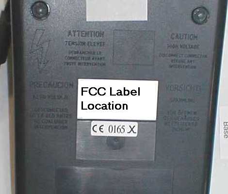
External Photos
Top View Front View Bottom View
ID Label/Location Info
P4432-150 FCC ID: PB8P4432-150 4432150000XXXXX
Internal Photos
Top Cover Removed RF Module Top View RF Module Shield Removed RF Module Bottom View
Test Report
FCC CERTIFICATION TEST REPORT for Dassault AT 9, rue Elsa Triolet 78373 PLAISIR cedex France FCC ID: PB8P4432-150 January 26, 2001 WLL PROJECT #: 5569X This report may not be reproduced, except in full, without the prior written consent of Washington Laboratories, Ltd. Dassault A.T. FCC ID:PB8P4432-150 WLL Project #:5569X i TABLE OF CONTENTS Statement of Qualifications 1.0INTRODUCTION............................................................................................................................................. 2 1.1S UMMARY ........................................................................................................................................................ 2 2.0DESCRIPTION OF EQUIPMENT UNDER TEST (EUT) ............................................................... 2 3.0TEST CONFIGURATION...............................................................................................................................3 3.1T ESTIN G A LGO RITHM ....................................................................................................................................... 3 3.2R ADIATED E MISSIONS T ESTIN G ........................................................................................................................ 3 3.2.1Radiated Data Reduction and Reporting .............................................................................................. 3 Tables Table 1.Radiated Emissions Results Table 2.Spurious Radiated Emissions (20 dBc) Table 3.System Under Test Table 4.Interface Cables Used Table 5.Measurement Equipment Used Exhibits Exhibit 1.Bandwidth Plots Appendices Appendix A.Statement of Measurement Uncertainty Dassault A.T. FCC ID:PB8P4432-150 WLL Project #:5569X 1 S of Q Dassault A.T. FCC ID:PB8P4432-150 WLL Project #:5569X 2 FCC CERTIFICATION TEST REPORT for FCC ID: PB8P4432-150 1.0Introduction This report has been prepared on behalf of Dassault A.T. to support the attached Application for Equipment Authorization. The test and application are submitted for a Frequency Hopping Spread Spectrum Transmitter under Part 15.247 of the FCC Rules and Regulations. The Equipment Under Test was the Dassault A.T. ARTEM A Base Charging/Docking Station , M/N: P4432-150. All measurements herein were performed according to the 1992 version of ANSI C63.4. The measurement equipment conforms to ANSI C63.2 Specifications for Electromagnetic Noise and Field Strength Instrumentation. Calibration checks are made periodically to verify proper performance of the measuring instrumentation. All measurements are performed at Washington Laboratories, Ltd. test center in Gaithersburg, MD. Site description and site attenuation data have been placed on file with the FCC's Sampling and Measurements Branch at the FCC laboratory in Columbia, MD. Washington Laboratories, Ltd. has been accepted by the FCC and approved by NIST NVLAP (NVLAP Lab Code: 200066-0) as an independent FCC test laboratory. All results reported herein relate only to the equipment tested. The measurement uncertainty of the data contained herein is ± 2.3 dB. Refer to Appendix A for Statement of Measurement Uncertainty. This report shall not be used to claim product endorsement by NVLAP or any agency of the US Government. 1.1Summary The Dassault A.T. ARTEMA Base Charging/Docking Station complies with the requirements for a Frequency Hopping Spread Spectrum Transmitter under Part 15.247 of the FCC Rules and Regulations. 2.0Description of Equipment Under Test (EUT) The Dassault A.T. ARTEMA Base Charging/Docking Station (EUT) is an AC pow ered charging /docking station for use with the Dassault A.T. ARTEMA US Portables Electronic Fund Transfer/Point of Sale terminals (FCC ID: PB8P4432-050). The radio located in the base is a Frequency Hopping Spread Spectrum transmitter operating in the 902 – 928 MHz frequency band. This radio is identical to the FHSS radio used in the ARTEMA US Portables (FCC ID: PB8P4432-050). The desktop mountable EUT is used for remote communications with the portable terminals, charging spare batteries and docking/charging the portable units. Dassault A.T. FCC ID:PB8P4432-150 WLL Project #:5569X 3 3.0Test Configuration To complete the test configuration required by the FCC, the transmitter was tested as a desktop orientation as in normal use. Cables were connected to the I/O ports during testing. 3.1Testing Algorithm The transmitter was configured to continuously transmit during testing. The unit was fixed (hopping disabled) to the Low Channel, Middle Channel and High Channel during the emissions testing. The unit w as tested w ith and w ithout a portable being docked on the charger base. Worst case emissions are recorded in the data tables. 3.2Radiated Emissions Testing The EUT was placed on an 80 cm high 1 x 1.5 meters non-conductive motorized turntable for radiated testing on a 3 meter open field test site. The emissions from the EUT w ere measured continuously at every azimuth by rotating the turntable. Biconical and log periodic broadband antennas were mounted on an antenna mast to determine the height of maximum emissions. The height of the antenna was varied between 1 and 4 meters. The peripherals were placed on the table in accordance with ANSI C63.4-1992. Cables were varied in position to produce maximum emissions. Both the horizontal and vertical field components were measured. The output from the antenna was connected, via a preamplifier, to the input of the spectrum analyzer. The detector function was set to quasi-peak or peak, as appropriate. The measurement bandwidth on the spectrum analyzer system was set to at least 120 kHz, with all post-detector filtering no less than 10 times the measurement bandwidth. For measurements above 1 GHz, the measurement bandwidth was set to 1MHz. 3.2.1Radiated Data Reduction and Reporting To convert the raw spectrum analyzer radiated data into a form that can be compared with the FCC limits, it is necessary to account for various calibr…
Text truncated - open the document above for the full version.
Test Setup Photos
Conducted Emissions Test Setup Radiated Emissions Test Setup
Contact Information
Applicant
Olivier Poitrenaud(R & D Engineer)
Technical Contact
Washington Laboratories, Ltd.Gregory M Snyder
[email protected]301/ 417-0220
7560 Lindbergh Drive · Gaithersburg, Maryland · United States
Non-Technical Contact
Washington Laboratories, Ltd.Brian J Dettling
[email protected]301/ 417-0220
Test Firm
Washington Laboratories, Ltd.Michael Violette
Technical Specifications
| # | Rule Parts | Frequency Range | Power Output |
|---|---|---|---|
| 1 | 15C | 903.8 MHz - 911.2 MHz | 17.10 mW |
Other Applications from Thales e- Transactions S.A.
PB8P4432-052
Sep 24, 2001Point of Sale Terminal
Equipment Class
DSS - Part 15 Spread Spectrum Transmitter
PB8P4432-051
Mar 28, 2001Point of Sale Terminal
Equipment Class
TNB - Licensed Non-Broadcast Station Transmitter