PBCFHD-252External Data Storage Device
Sarotech Co., Ltd.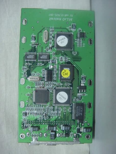
Click to zoom
Application Details
- Equipment Class
- JBP - Part 15 Class B Computing Device Peripheral
- Date of Grant
- Jan 17, 2001
- Application Purpose
- Original Equipment
- Date of Application
- Jan 17, 2001
- Equipment Note
- External Data Storage Device
- Company
- Sarotech Co., Ltd.
- Country
- South Korea
Documents & Files
Document Text
Text extracted from the exhibit documents filed with the FCC. Open a document above to read the original.
Users Manual
FLEX-HDD(FHD-352, FHD-252) User’s Manual I. General Information H/W & S/W REQUIREMENTS For Mac OS Users : 1. A Macintosh computer with built-in FireWire™ and USB ports. 2. Mac OS 8.6 or higher For Windows PC Users : 1. A PC with at least 200MHz Pentium and built-in USB, FireWire™ port(s) or a USB, FireWire™ PCI Card 2. Windows 98SE or higher PACKAGE CONTENTS (1) 1394 connecting cable(6pin-6pin) (1) USB connecting cable(A to B) (1) AC power cable( FHD-352UF User’s only) *** Note for FHD-252Users Some notebook computers may not supply the required voltage to power your external-HDD. In this case, the external AC/DC power adapter(optional) will be needed. (1) Install driver CD (1) User’s Manual (1) Carrying bag(option) II. Installation & Operation CASE ASSEMBLING 1. Press down the top of the case and pull it apart. Note: Try not to use sharp objects to open it; it might damage the inner IC broad. 2. Remove the case and disassemble the unit. 3. Connect the IDE hard disk to the connector. Note: Make sure the pins match the connecter 4. Connect the DC power cable to the hard disk(FHD-352 Users only) 5. Secure the hard drive on the bottom of case with 4 screws(big size) provided after connecting. Note: Do not tighten the screws too much. 6. Get ready to put everything back together and secure top and bottom cases with 2 screws(small size). Note: Do not connect power at this time FIREWIRE INSTALLATION For Mac OS users 1. Insert provided cd-rom into your cd-drive. The cd icon will pop up on the screen. 2. On the cd-rom window, you’ll find FWSBP2DiskDriver in FireWire folder. 3. Make sure you have FireWire Enabler and FireWire Support in your extension folder. You may already have FireWire Enabler and FireWire Support in your Extension folder if you are using Mac OS 8.6 or higher. 4. Copy FWSBP2DiskDriver to Extension Folder in System folder. 5. Plug the AC power cable into the power port.(FHD-352UF users only) 6. Now make sure your external hard drive is powered on and the FireWire™ cable is attached, then plug the FireWire™ cable into your computer. 7. You can use your external hard drive without restarting your computer. CAUTION Do not disconnect the hard drive while the drive is mounted on the desktop. If you disconnect the drive while copying files to or from the drive, data may be lost or the disk may be damaged. To unplug the hard drive, drag the icon for the hard drive to the trash and wait until the disk icon disappears from the desktop. For Windows98 Users 1. If you have already installed FireWire Host Adaptor card in your PC, you don’t need any additional S/W installation to use your FlexHD. 2. Plug the AC Adapter into the power port on the FireWire™ Hard Drive.(FHD-352 Users only) 3. Plug one each of the FireWire™ cable into FireWire™ port on your PC and on your Hard drive. 4. You’ll need to format the FireWire™ Hard Drive to work on your PC.( In case it’s not formatted ) CAUTION Do not disconnect the hard drive while your computer is running. Data loss could result. Power down the computer and disconnect the drive. Hot swap function will be supported later on. USB INSTALLATION For Mac OS users 1. Insert provided cd-rom into your cd-drive. The cd icon will pop up on the screen. 2. On the cd-rom window, you’ll find Setup file in USB. 3. Double click this setup file and INSTALL then the driver will be installed automatically. 4. Plug the AC adapter into the power port.(FHD352 users only) 5. Now make sure your external hard drive is powered on and the USB cable is attached, then plug the USB cable into your computer. 6. You can use your external hard drive without restarting your computer. CAUTION Do not disconnect the hard drive while the drive is mounted on the desktop. If you disconnect the drive while copying files to or from the drive, data may be lost or the disk may be damaged. To unplug the USB Hard Drive, drag the icon for the USB Hard Drive to the trash and wait until the disk icon disappears from the desktop. For Windows98 Users 1. Insert provided cd-rom into your cd-drive. 2. On the cd-rom window, you’ll find Setup file in USB\Windows98 folder 3. Double click this file and INSTALL then the drive will be installed automatically. 4. Plug the AC power cable into the power port on the USB Hard Drive.(FHD-352 Users only) 5. Plug one each of the USB cable into USB port on your PC and on your Hard drive. 6. You’ll need to format the USB Hard Drive to work on your PC.( In case it’s not formatted ) CAUTION Do not disconnect the hard drive while your computer is running. Data loss could result. Power down the computer and disconnect the drive. Hot swap function will be supported later on. For Windows2000 Users 1. Insert provided cd-rom into your cd-drive. 2. On the cd-rom window, you’ll find usbstor.inf in USB\Windows2000 folder 3. Copy usbstor.inf to C:\winNT\INF( usbstor.inf is already exists in C:\winNT\INF, you should replace this file to usbstor.inf provided) 4. Plug the AC Adapter into the power port on the USB Hard Drive.(FHD-352 Users only) 5. Plug one each of the USB cable into USB port on your PC and on your Hard drive. 6. You’ll need to format the USB Hard Drive to work on your PC.( In case it’s not formatted ) CAUTION Do not disconnect the hard Drive while copying files to or from the drive, data may be lost or the disk may be damaged. You may unplug the drive if it is not doing any job. FCC INFORMATION TO THE USER This equipment has been tested and found to comply with the limits for a Class B digital device, pursuant to part 15 of the FCC Rules. These limits are designed to provide reasonable protection against harmful interference in a residential installation. This equipment generates, uses and can radiate radio frequency energy and, if not installed and used in accordance with the instructions, may cause harmful interference to radio communications. However, there is no guarantee that interference will not occur in a particular installation. If this equipment does cause…
Text truncated - open the document above for the full version.
Block Diagram
FHD-252 Block Diagram 1394 CONN 1394 V GND 24.576MHz DC/DC PWM REGULATOR 48MHz Quick S/W TO HDD CONN. 1394 to ATAPI USB CONN 1394 CONN 1394 CONN . 1394 PHY DC/DC USB TO ATAPI USB V HDD POWER 1394 Data 1394 Data 5.0V 3.3V Hdd Ctrl
ID Label/Location Info
FCC ID. : PBCFHD-252 ONETECH Testing & Evaluation Lab . IDENTIFICATION LABEL LOCATION: PROPOSED FCC ID LABEL The label of FCC ID. will be affixed to the bottom side of product. FCC ID : PBCFHD-252 Model Name: FHD-252 This device complies with Part 15 of the FCC Rules. Operation is subject to the following two conditions: (1) this device may not cause harmful interference, and (2) this device must accept any interference received, including interference that may cause undesired operations SAROTECH CO., LTD Made in Korea FCC ID AREA
Test Report
Page 1 of 13 FCC ID. : Error! Unknown docume nt prope rty name . File No. : Error! Unknown docume nt prope rty name . This report shall not be reproduced except in full without our written approval.FCC-004 (Rev.0) HEAD OFFICE : #505 SK APT. Factory 223-28, Sangdaewon 1 Dong, Jungwon- Gu, Seongnam- C ity, K yunggi- Do, 462-121, Korea (TEL: 82- 31-746-8500 FAX: 82-31-746-8700 ) EM C Te s ting De pt : 426-1 Daessangryung- Ri, C howol- Myun, K wangju- K un, K yunggi- Do 464-860 Korea. (TEL: 82- 31-765-8289 FAX: 82-31-766-2904) ONETECH Testing & Evaluation Lab . ELECTROMAGNETIC EMISSION COMPLIANCE REPORT Test report file number : E00DR-004 Applicant : SAROTECH CO., LTD. Address: Hangang Bldg., 1549-7, Seocho-Dong, Seocho-Gu, 137-070, Korea Manufacture r : SAROTECH CO., LTD. Address: Hangang Bldg., 1549-7, Seocho-Dong, Seocho-Gu, 137-070, Korea Type of Equipme nt : EXTERNAL HDD ENCLOSURE (Class B Computing De vice Pe riphe ral) FCC ID: PBCFHD-252 Model / Type No. : FHD-252 Se rial numbe r: N/ A Total page of Report: 13 pages (including this page) Date of Incoming: November 04, 2000 Date of issuing : December 04, 2000 SUMMARY The equipment complies with the regulation; FCC PART 15 SUBPART B, SECTION 15.101 This test report contains only the result of a single test of the sample supplied for the examination. It is not a general valid assessment of the features of the respective products of the mass-production Prepared by: Reviewed by: G. W. Lee/ Ass. Chief EngineerY. K. Kwon/ Chief Engineer EMC Dept.EMC Dept. ONETECH Corp.ONETECH Corp. Page 2 of 13 FCC ID. : Error! Unknown docume nt prope rty name . File No. : Error! Unknown docume nt prope rty name . This report shall not be reproduced except in full without our written approval.FCC-004 (Rev.0) HEAD OFFICE : #505 SK APT. Factory 223-28, Sangdaewon 1 Dong, Jungwon- Gu, Seongnam- C ity, K yunggi- Do, 462-121, Korea (TEL: 82- 31-746-8500 FAX: 82-31-746-8700 ) EM C Te s ting De pt : 426-1 Daessangryung- Ri, C howol- Myun, K wangju- K un, K yunggi- Do 464-860 Korea. (TEL: 82- 31-765-8289 FAX: 82-31-766-2904) ONETECH Testing & Evaluation Lab . CONTENTS Page 1. VERIFICATION OF COMPLIANCE...............................................................................................................................3 2. GENERAL INFORMATION ............................................................................................................................................. 4 2.1 P RODUCT D ESCRIPTIO N .................................................................................................................................................... 4 2.2 R ELATED S UBMITTAL ( S ) / G RANT ( S ) ................................................................................................................................ 4 2.3 T EST S YSTEM D ETAILS ..................................................................................................................................................... 5 2.4 T EST M ETHODOLOGY ....................................................................................................................................................... 5 2.5 T EST F ACILITY ................................................................................................................................................................. 5 3. SYSTEM TEST CONFIGURATION................................................................................................................................. 6 3.1 J USTIFICATIO N ................................................................................................................................................................. 6 3.2 EUT EXERCISE S OFTWARE ............................................................................................................................................... 6 3.3 C ABLE D ESCRIPTIO N ........................................................................................................................................................ 6 3.4 N OISE S UPPRESSION P ARTS ON C ABLE ............................................................................................................................. 7 3.5 E QUIPMENT M ODIFICATIONS ........................................................................................................................................... 7 3.6 C ONFIGURATION OF T EST S YSTEM ................................................................................................................................... 7 4. PRELIMINARY TEST........................................................................................................................................................ 8 4.1 AC P O WER LIN E C ONDUCTED E MISSION T EST ................................................................................................................. 8 4.2 R ADIATED E MISSION T EST ............................................................................................................................................... 8 5. FINAL RESULT OF MEASURMENT .............................................................................................................................. 9 5.1 C ONDUCTED E MISSION T EST ............................................................................................................................................ 9 5.2 R ADIATED E MISSION T EST ............................................................................................................................................. 12 6. FIELD STRENGTH CALCULATION............................................................................................................................ 14 7. LIST OF TEST EQUIPMENT ......................................................................................................................................... 15 Page 3 of 13 FCC ID. : Error! Unknown docume nt prope rty name . File No. : Error! Unknown docu…
Text truncated - open the document above for the full version.
Test Setup Photos
Conducted Emission Test Radiated Emission Test
Contact Information
Applicant
Chung-Young So(Manager)
Technical Contact
ONETECH CORP.Y.K. KWON
[email protected]+82-31-765-8289
461-1, Daessangryung-Ri, Chowol-Myun · Kyunggi-Do · South Korea
Test Firm
ONETECH Corp.Y. Kwon
Technical Specifications
| # | Rule Parts | Frequency Range | Power Output |
|---|---|---|---|
| 1 | 15B | - | - |
Other Applications from Sarotech Co., Ltd.
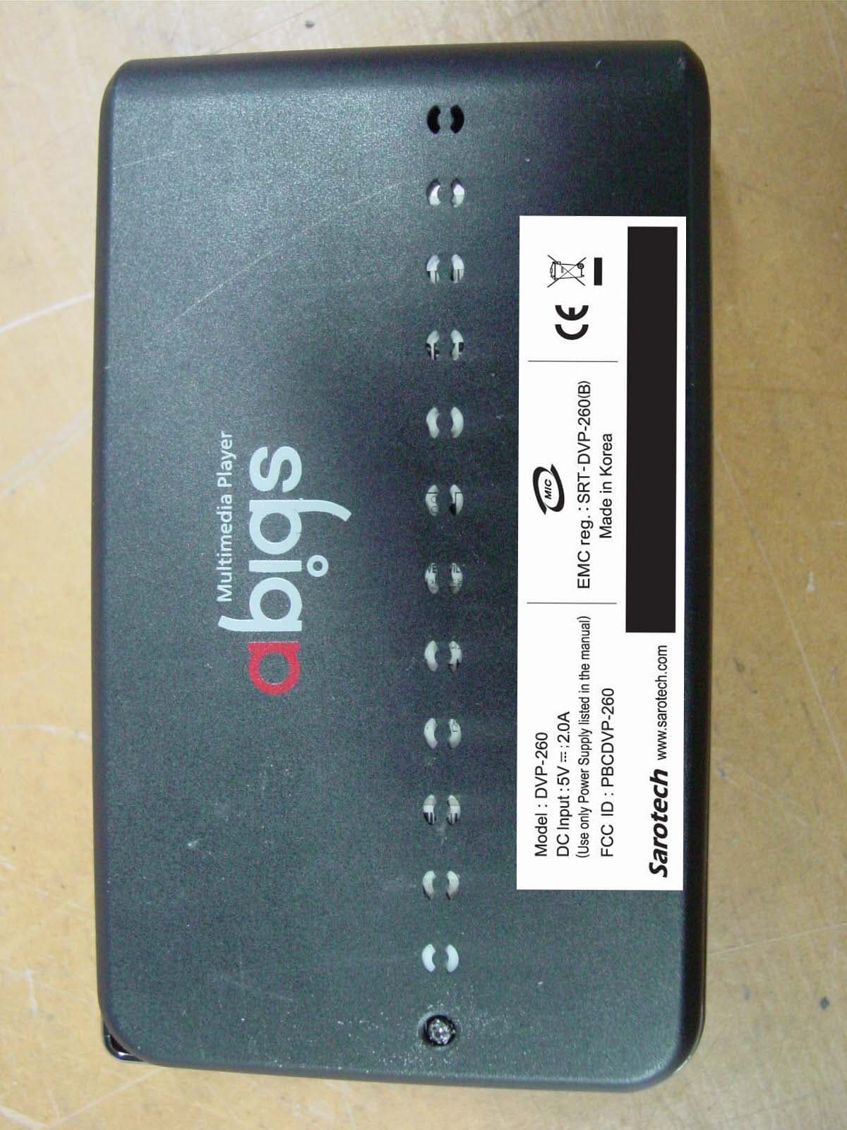
PBCDVP-260
Mar 18, 2007Multi Media Player
Equipment Class
JBP - Part 15 Class B Computing Device Peripheral
PBCDVP-570
Nov 19, 2006Multi Media Player
Equipment Class
JBP - Part 15 Class B Computing Device Peripheral
PBCDVP-370
Mar 28, 2006Multimedia Player
Equipment Class
DXX - Part 15 Low Power Communication Device Transmitter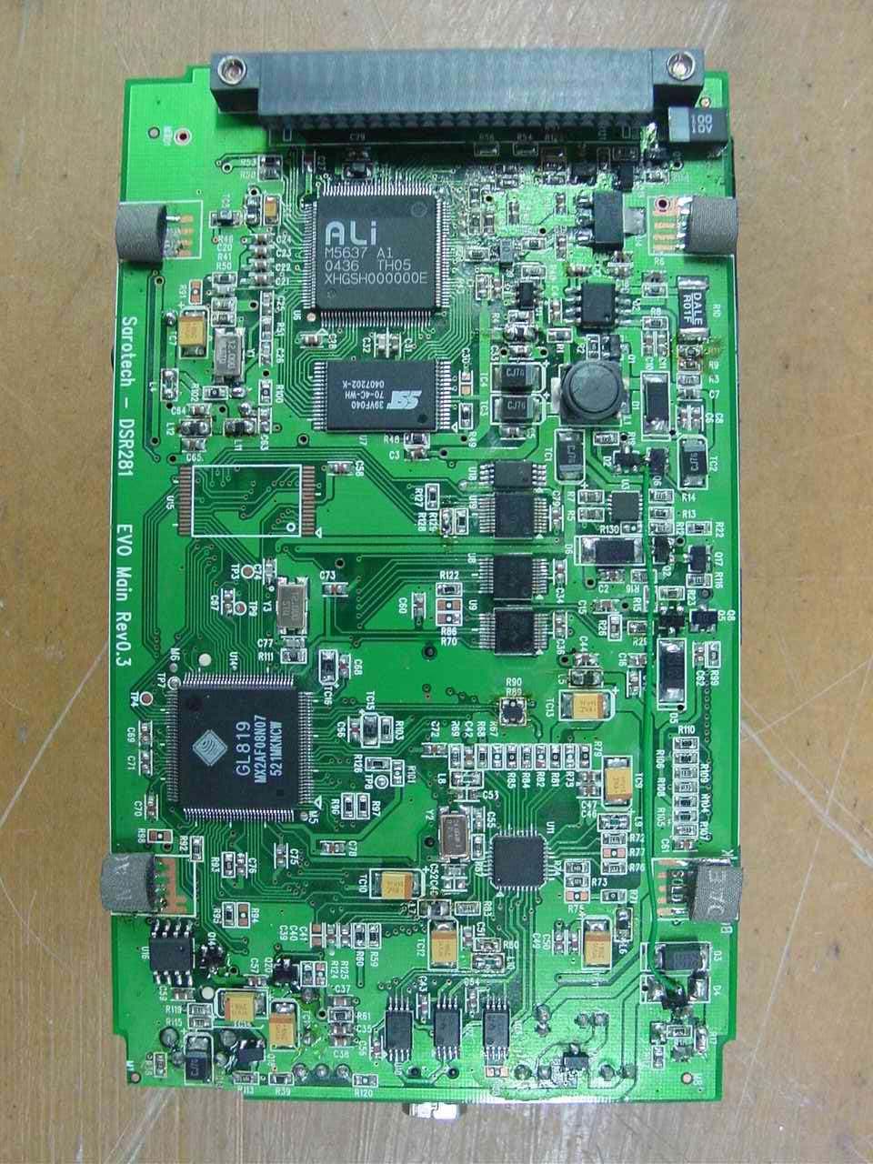
PBCDSR281
Jan 18, 2006Photo Storage
Equipment Class
JBP - Part 15 Class B Computing Device Peripheral
PBCNHD-355
Sep 15, 2005Network Storage
Equipment Class
JBP - Part 15 Class B Computing Device Peripheral