PBJV3000-CBase Station Transmitter
Vyyo
Click to zoom
Application Details
- Equipment Class
- TNB - Licensed Non-Broadcast Station Transmitter
- Date of Grant
- Mar 02, 2006
- Application Purpose
- Original Equipment
- Date of Application
- Mar 02, 2006
- Equipment Note
- Base Station Transmitter
- Frequency Range
- 741.00000000 - 745.00000000
- Company
- Vyyo
- Country
- United States
Documents & Files
Document Text
Text extracted from the exhibit documents filed with the FCC. Open a document above to read the original.
Users Manual
WMTS T1 Access Concentrator V3000 Network Release 3.6 P/N: 3BR-0014A System Configuration Guide Manual Version: 1.1.15 Copyright and Trademark Information: © 2005 Vyyo Inc. All rights reserved. Vyyo Inc. reserves the right to alter the equipment specifications and descriptions in this publication without prior notice. No part of this publication shall be deemed part of any contract or warranty unless specifically incorporated by reference into such contract or warranty. The information contained herein is merely descriptive in nature, and does not constitute a binding offer for the sale of the product described herein. Any use of the Vyyo Inc. logo or trademarks is forbidden without prior written approval from Vyyo Inc. All trademarks mentioned herein are the property of their respective owners. Table Of Contents Table Of Contents................................................................................3 Installation and Safety Information......................................................7 Chapter 1.System Configuration Introduction..................................10 1.1Overview...............................................................................................10 1.2Equipment Capabilities.........................................................................13 1.3WMTS...................................................................................................13 1.4Modems................................................................................................16 1.4.1Modems with DOCSIS and IP only................................................16 1.4.2Modems with DOCSIS, IP and E1/T1............................................17 1.4.3Modems with DOCSIS, IP and PSTN............................................18 1.4.4Modems with DOCSIS and IP Only With Built in UHF Radio........19 1.5Modem Capabilities Matrix...................................................................20 Chapter 2.Configuration Overview...................................................21 2.1Network Servers...................................................................................21 2.1.1DHCP Server.................................................................................21 2.1.2TFTP Server..................................................................................21 2.1.3Time-of-Day (TOD) Server............................................................21 2.2RF Link Layer.......................................................................................21 2.3DOCSIS Layer......................................................................................22 2.4IP Layer................................................................................................23 2.5E1/T1 Layer..........................................................................................24 2.6Configuration Tools and Files Matrix....................................................26 Chapter 3.The Modem Initialization Process...................................28 3.1Modem Initialization Sequence.....................................................28 3.1.1Power-On Self Test..........................................................................28 3.1.2Downstream Synchronization.............................................................29 3.1.3Obtaining Upstream Parameters........................................................29 www.vyyo.com Table Of Contents – p. 4 3.1.4Ranging..........................................................................................29 3.1.5Establish IP Connectivity...................................................................29 3.1.6Establish Time of Day.......................................................................30 3.1.7Transfer Operational Parameters.......................................................30 3.1.8Registration.....................................................................................30 3.1.9Baseline Privacy Initialization (BPI).....................................................30 Chapter 4.Overview of the WMTS and Modem Configuration........31 Chapter 5.Adding a Modem to the WMTS.......................................34 5.1Editing the Modem Configuration File...................................................35 5.1.1Setting the Upstream Channel......................................................35 5.1.2Setting the Downstream Frequency..............................................38 5.1.3Setting Concatenation and Fragmentation Capabilities.................39 5.1.4Setting Upstream QoS (Class of Service) for IP Data...................40 5.1.5Setting Additional Downstream and Upstream Channels..............41 5.1.6Setting the Maximum Number of CPEs.........................................42 5.2DHCP Settings for the Modem.............................................................43 5.2.1IpLease DHCP Server: Editing and running the CM.SRC File......43 5.2.2Windows 200x Server Edition: Modifying the DHCP Options.......48 5.3Configuring the WMTS.........................................................................57 5.3.1Setting the WMTS Upstream Parameters.....................................57 5.3.2Setting the WMTS Downstream Parameters.................................60 5.4Setting the Modem’s Downstream Frequency......................................62 5.5Verifying the Modem Downstream and Upstream Status.....................69 5.6Using an HTTP Connection to View Modem Operation........................71 5.6.1Viewing the internal modem HTML pages:....................................71 5.6.2Viewing the Connection Page.......................................................73 5.6.3Viewing the Software Page...........................................................74 5.6.4Viewing the Security Page.............................................................75 Chapter 6.Configuring a T1 Connection..........................................76 6.1Configure the Modem for T1 Operation.......................…
Text truncated - open the document above for the full version.
Users Manual
www.vyyo.com Table Of Contents – p. 1 XMTS T1 Access Concentrator XMTS Network Release 3.5.x P/N: 9090-090 System Configuration Guide Manual Version: 1.0.13 www.vyyo.com Table Of Contents – p. 2 Copyright and Trademark Information: © 2005 Vyyo Inc. All rights reserved. Vyyo Inc. reserves the right to alter the equipment specifications and descriptions in this publication without prior notice. No part of this publication shall be deemed part of any contract or warranty unless specifically incorporated by reference into such contract or warranty. The information contained herein is merely descriptive in nature, and does not constitute a binding offer for the sale of the product described herein. Any use of the Vyyo Inc. logo or trademarks is forbidden without prior written approval from Vyyo Inc. All trademarks mentioned herein are the property of their respective owners. www.vyyo.com Table Of Contents – p. 3 Table Of Contents Table Of Contents................................................................................3 Installation and Safety Information......................................................7 Chapter 1.System Configuration Introduction..................................10 1.1Overview...............................................................................................10 1.2Equipment Capabilities.........................................................................13 1.3XMTS....................................................................................................13 1.4Modems................................................................................................16 1.4.1Modems with DOCSIS and IP only................................................16 1.4.2Modems with DOCSIS, IP and E1/T1............................................17 1.4.3Modems with DOCSIS, IP and PSTN............................................18 1.4.4Modems with DOCSIS and IP Only With Built in UHF Radio........19 1.5Modem Capabilities Matrix...................................................................20 Chapter 2.Configuration Overview...................................................21 2.1Network Servers...................................................................................21 2.1.1DHCP Server.................................................................................21 2.1.2TFTP Server..................................................................................21 2.1.3Time-of-Day (TOD) Server............................................................21 2.2RF Link Layer.......................................................................................21 2.3DOCSIS Layer......................................................................................22 2.4IP Layer................................................................................................23 2.5E1/T1 Layer..........................................................................................24 2.6Configuration Tools and Files Matrix....................................................26 Chapter 3.The Modem Initialization Process...................................28 3.1Modem Initialization Sequence.....................................................28 3.1.1Power-On Self Test..........................................................................28 3.1.2Downstream Synchronization.............................................................29 3.1.3Obtaining Upstream Parameters........................................................29 www.vyyo.com Table Of Contents – p. 4 3.1.4Ranging..........................................................................................29 3.1.5Establish IP Connectivity...................................................................29 3.1.6Establish Time of Day.......................................................................30 3.1.7Transfer Operational Parameters.......................................................30 3.1.8Registration.....................................................................................30 3.1.9Baseline Privacy Initialization (BPI).....................................................30 Chapter 4.Overview of the XMTS and Modem Configuration.........31 Chapter 5.Adding a Modem to the XMTS........................................34 5.1Editing the Modem Configuration File...................................................35 5.1.1Setting the Upstream Channel......................................................35 5.1.2Setting the Downstream Frequency..............................................38 5.1.3Setting Concatenation and Fragmentation Capabilities.................39 5.1.4Setting Upstream QoS (Class of Service) for IP Data...................40 5.1.5Setting Additional Downstream and Upstream Channels..............41 5.1.6Setting the Maximum Number of CPEs.........................................42 5.2DHCP Settings for the Modem.............................................................43 5.2.1IpLease DHCP Server: Editing and running the CM.SRC File......43 5.2.2Windows 200x Server Edition: Modifying the DHCP Options.......48 5.3Configuring the XMTS..........................................................................57 5.3.1Setting the XMTS Upstream Parameters......................................57 5.3.2Setting the XMTS Downstream Parameters..................................63 5.4Setting the Modem’s Downstream Frequency......................................67 5.5Verifying the Modem Downstream and Upstream Status.....................74 5.6Using an HTTP Connection to View Modem Operation........................76 5.6.1Viewing the internal modem HTML pages:....................................76 5.6.2Viewing the Connection Page.......................................................78 5.6.3Viewing the Software Page...........................................................79 5.6.4Viewing the Security Page.............................................................80 Chapter 6.Configuring a …
Text truncated - open the document above for the full version.
Cover Letter(s)
Date: 3 October 2005 Compliance Certification Services Certification Division 561F Monterey Road Morgan Hill, CA 95037 To whom it may concern: We, the undersigned, hereby authorize THOMAS N COKENIAS, d.b.a. T.N. Cokenias Consulting, to act on our behalf in all manners relating to application for equipment authorization through the Certification Division of Compliance Certification Services (CCS) , including signing of all documents relating to these matters. Any and all acts carried out by THOMAS N COKENIAS on our behalf shall have the same effect as acts of our own. We, the undersigned, hereby certify that we are not subject to a denial of federal benefits, that includes FCC benefits, pursuant to Section 5301 of the Anti-Drug Abuse Act of 1988, 21 U.S.C. 853(a). In authorizing THOMAS N COKENIAS as our agent, we still recognize that we are responsible to: a) comply with the relevant provisions of the certification program; b) make all necessary arrangements for the conduct of the evaluation, including provision for examining documentation and access to all areas, records (including internal audit reports) and personnel for the purposes of evaluation (e.g. testing, inspection, assessment, surveillance, reassessment) and resolution of complaints; c) make claims regarding certification only in respect of the scope for which certification has been granted; d) do not use our product certification in such a manner as to bring the Certification Division into disrepute and not make any statement regarding our product certification which the Certification Division may consider misleading or unauthorized; e) upon suspension or cancellation of certification, discontinue use of all advertising matter that contains any reference thereto and return any certification documents as required by the Certification Division; f) use certification only to indicate the products are certified as being in conformity with specified standards; g) endeavor to ensure that no certificate or report nor any part thereof is used in a misleading manner; h) ensure that any reference to our product certification in communication media such as documents, brochures or advertising, complies with the requirements of the Certification Division; i) keep a record of all complaints made known to the us relating to the product’s compliance with requirements of the relevant standard and to make these records available to the Certification Division when requested; j) take appropriate action with respect to such complaints and any deficiencies found in products or services that affect compliance with the requirements for certification; k) document the actions taken. This authorization is valid until further written notice from the applicant. Sincerely Yours, Dr. Mike Ritter, CTO Vyyo, Inc.
Cover Letter(s)
tel: 650-726-1263 fax: 650-726-1252 [email protected] Thomas N. Cokenias EMC &Radio Approvals Test & Consulting Services for Commercial, Military, International Compliance P.O. Box 1086 El Granada, CA 94018 Compliance Certification Services 25 July 2005 561F Monterey Road Morgan Hill, CA 95037 Attention: Application Examiner Reviewing Engineer Re: Request that certain portions of the application are kept from routine public review per section 0.459 of the Rules. Applicant: Vyyo Inc. FCC ID: PBJV3000-C Part 27 740-746 MHz C-Band Transmitter To whom it may concern, Request is hereby submitted, on behalf of my client Vyyo to withhold from public review certain portions of the application for equipment certification for the referenced FCC identifier per section 0.459 of the Rules. In particular, the following sections of the application and report are requested to be kept confidential: Block Diagrams Schematic Operational Description Bill of materials/Parts List Rationale for request for confidentiality: Vyyo has invested considerable time and materials in research and development to produce the referenced product. Disclosure of the confidential portions of this application to competitors would give them competitive advantage in developing similar products. If you have questions or need further information, please contact the undersigned. Sincerely, tel: 650-726-1263 fax: 650-726-1252 [email protected] THOMAS N. COKENIAS EMC Consultant Agent for Sensus Metering Systems
Cover Letter(s)
On Jan 8, 2006, at 6:44 PM, Mike Kuo wrote: Question #1: Please provide internal photos of V3000-WMTS Modulator. The photos submitted only contain external view of complete system. ANS 1 Internal photos attached Question #2: Two manual files were submitted. One is V3000 system configuration guide and the other is XMTS system configuration guide. There is no tune up procedures or operational description have been submitted. If tune up procedure or operational description are contained in manual files, please extract such information and submit the information as tune up procedure and operational description. ANS 2 The attached draft Factory Acceptance Test (FATc) has tune-up and operational description Question #3: FCC ID label format and proposed label location: The FCC DoC logo is used but the orientation of FCC DoC logo is up-side-down. Please make necessary correction. Since this system is licensed transmitter per Part 27 requirement, FCC DoC logo is not applicable to this system. You may want to remove it. In addition, the proposed FCC ID label location is placed on the outside of 19 inches rack. Per the system configuration diagram, there are additional FCC certified device ( FCC ID:QH5TAU100 , 100W amplifier ) within the system. If FCC ID:PBJV3000-C is placed on the outside of system, it may mislead the user manual that PBJ3000-C is included 100W amplifier. Suggest to place PBJV3000-C on the V3000-WMTS unit. ANS3 Revised FCC label and label location are attached. Question #4: Please provide technical information to address RF exposure compliance per section 27.52 /2.1091 requirements. ANS4 RF exposure is addressed at time of licensing. Antennas are typically installed on towers, at least 50' above ground, more typically 200-400' in the air. The Rules limit eirp to 1000 watts or less. At 50 ft (15m) E, 15m = SQRT(1000)/15 = 31.6/15 = 2.1 V/m, well below uncontrolled limit of 61 V/m Question #5: As indicated in section 27.50(c), the output power limitation is based upon the type of service and antenna height. In the user manual, there is no such information provided to the installer. Please address. ANS5 Antennas are typically installed on towers, at least 50' above ground, more typically 200-400' in the air Question #6: Please address signal strength requirement as stated in section 27.55(a)(2) and 27.55(b). ANS 6 The field strength contours are determined at time of licensing and are a function of licensee antenna type, antenna height, and local terrain. Question #7 : Please provide additional test data to address section 27.53(f) for adjacent to frequency block requirement. ANS 7 Bandedge measurements have been inserted into the report, see Plot 8B and Plot 10B. The revised report is attached Question #8 : Please submit Part list. ANS8 Parts list attached Best Regards Mike Kuo The items indicated above must be submitted before processing can continue on the above referenced application. Failure to provide the requested information within 30 days of the original e-mail date may result in application dismissal and forfeiture of the filing fee. Also, please note that partial responses increase processing time and should not be submitted. Any questions about the content of this correspondence should be directed to the e-mail address listed below the name of the sender.
External Photos
Vyyo Inc.FCC ID: PBJV3000-C C-Band Base Station External/Internal Photographs Vyyo Inc. FCC ID: PBJV3000-C C-Band Base Station External/Internal Photographs Vyyo Inc.FCC ID: PBJV3000-C C-Band Base Station External/Internal Photographs diplexer and filters Vyyo Inc.FCC ID: PBJV3000-C C-Band Base Station External/Internal Photographs Vyyo Inc.FCC ID: PBJV3000-C C-Band Base Station External/Internal Photographs Vyyo Inc.FCC ID: PBJV3000-C C-Band Base Station External/Internal Photographs
ID Label/Location Info
VYYO Inc. FCC ID: PBJV3000-C DRAFT FCC ID label and label location Vyyo Inc. FCC ID: PBJV3000-C This device complies with Part 15 of the FCC Rules. Operation is subject to the following two conditions: (1) This device may not cause harmful interference, and (2) This device must accept any interference received, including interference than may cause undesired operation Model No.: V3000-C
Internal Photos
Vyyo Inc.FCC ID: PBJV3000-C C-Band Base Station External/Internal Photographs Vyyo Inc. FCC ID: PBJV3000-C C-Band Base Station External/Internal Photographs Vyyo Inc.FCC ID: PBJV3000-C C-Band Base Station External/Internal Photographs diplexer and filters Vyyo Inc.FCC ID: PBJV3000-C C-Band Base Station External/Internal Photographs Vyyo Inc.FCC ID: PBJV3000-C C-Band Base Station External/Internal Photographs Vyyo Inc.FCC ID: PBJV3000-C C-Band Base Station External/Internal Photographs
Internal Photos
Vyyo Inc., FCC ID: PBJV3000-A WMTS Internal Photographs WMTS – PCBA Upstream Vyyo Inc., FCC ID: PBJV3000-A WMTS Internal Photographs WMTS – PCBA Downstream Vyyo Inc., FCC ID: PBJV3000-A WMTS Internal Photographs WMTS – PCBA Hostmaster Vyyo Inc., FCC ID: PBJV3000-A WMTS Internal Photographs WMTS – PCBA Universal Card3
Test Report
Vyyo Inc. FCC ID: PBJV3000-C page 1 of 30 Vyyo Inc. FCC ID: PBJV3000-C FCC Rule Part: 27 Section 27.5(c) Block C: 740–746 MHz General Overview A description of the theory of operation and product configuration is found in an attachment to this application and report. SPECIFICATIONS Transmitter TX operating frequency: 741-745 MHz TX output power: 64.1 watts Peak/ 17 watts Average Digital Modulation: 64QAM in 1.75 MHz channel Modulation is internally generated and limited Power requirements: 120 VAC or 48 VDC Antenna connector: N- type Frequency Tolerance Remain in band: -30 to +50 C 85%-115% supply voltage at 20C Block diagram and theory of operation is provided in a separate attachment. Test Summary Results Test Description Plot or Table No . Test Results RF Power Output Plots 1- 4 Pass Occupied Bandwidth Plots 5 - 7 Pass Spurious and Harmonic Emissions at Antenna Terminals Plots 8-10 Pass Field Strength of Spurious and Harmonic Radiation Table 1-3 Pass Frequency Stability Plots 11-17 Pass Vyyo Inc. FCC ID: PBJV3000-C page 2 of 30 FCC CERTIFICATION INFORMATION The following information is in accordance with FCC Rules, 47CFR Parts 1 and 2. 1.1307(b) RF exposure information is provided in a separate attachment in the form of maximum permissible exposure (MPE) data. 2.1033(c)1 Applicant: Vyyo Inc. 4015 Miranda Avenue Palo Alto, CA. 94304 2.1033(c)2 FCC ID: PBJV3000-C 2.1033(c)3 Installation instructions are found in separate document. 2.1033(c)4 Emission type: 64QAM Emission designator: 1M52W1D 2.1033(c)5 Frequency range: 741-745 MHz 2.1033(c)6 Range of Operating Power 64.1 watts Peak/ 17 watts Average Maximum, variable in 1 dB steps 2.1033(c)7 Maximum Power Rating 64.1 watts Peak/ 17 watts Average Maximum allowed per Section 27.50(c)1: 50 kW ERP 2.1033(c)8 Applied voltages and currents into the final transistor elements Refer to schematics, separate submission accompanying this application 2.1033(c)9 Tune-up procedure Refer to installation instructions. Vyyo Inc. FCC ID: PBJV3000-C page 3 of 30 2.1033(c)10 Circuit and Functional Block Diagram, Description of Circuitry Product schematics are provided in separate attachments. Circuit description and theory of operation are found in separate attachment. 2.1033(c)11 FCC ID Label Refer to separate attachment. 2.1033(c)12 Product Photographs Refer to separate attachment. 2.1033(c)13 Description of Modulation System 64QAM produced by internal DOCSIS cable modem Vyyo Inc. FCC ID: PBJV3000-C page 4 of 30 2.1033(c)14 Test Data per 2.1046 – 2.1057 Test Equipment List TEST EQUIPMENT LIST Name of EquipmentManufacturerModel No.Serial No.Due Date EMI Receiver, 9 kHz ~ 2.9 GHzHP8542E3942A002863/29/06 RF Filter SectionHP85420E3705A002563/29/06 Antenna, Bilog 30MHz ~ 2GhzSunol SciencesJB1A1210033/3/06 Signal Generator 2 -40 GHzR & SSMP04DE 342106/8/06 Antenna, Horn 1 ~ 18 GHzEMCO311522384/22/06 Antenna, Horn 1 ~ 18 GHzEMCO311567174/22/06 Antenna, Horn 1 ~ 18 GHzETS3117293104/22/06 Peak Power MeterAgilentE4416AGB412911602/9/06 Peak / Average Power SensorAgilentE9327AUS404407552/10/06 Spectrum Analyzer 3 Hz ~ 44 GHzAgilentE4446AUS420702201/1/06 Temperature / Humidity ChamberThermotronSE 600-10-10298006/10/06 Hi gh Power AttenuatorBIRD ELECTRONIC CORP 8343-200970N/A 2.1046 RF Output Power Measurements Test set-up: Figure 1 coaxial cable (2 dB loss measured) Total offset: 20 dB + 30 dB + 2 dB = 52 dB Test Procedures The transmitter was set to produce the required 64QAM modulation. The spectrum analyzer was set to measure total channel power for LOW, MID, and HIGH channels. Test Results Maximum results were 64 watts Peak, 17 watts Average. Refer to spectrum analyzer plots below. 20 dB 30dB spectrum analyzer Vyyo Inc. FCC ID: PBJV3000-C page 5 of 30 Plot#1 - Low Channel Output Power, AVERAGE Vyyo Inc. FCC ID: PBJV3000-C page 6 of 30 Plot#2 - Low Channel Output Power, PEAK Vyyo Inc. FCC ID: PBJV3000-C page 7 of 30 Plot#3 - Mid Channel Output Power Vyyo Inc. FCC ID: PBJV3000-C page 8 of 30 Plot#4 -High Channel Output Power Vyyo Inc. FCC ID: PBJV3000-C page 9 of 30 Section 2.1049 Occupied Bandwidth Requirement/Limit: 22.531 Test set-up: Refer to Figure 1, above Test Procedures: Using the spectrum analyzer Occupied Bandwidth measurement function, the 99% occupied bandwidth was measured for the EUT at LOW, MID, and HIGH channels with the EUT operating at full rated power. Test Results: Refer to spectrum analyzer displays below. Vyyo Inc. FCC ID: PBJV3000-C page 10 of 30 Plot#5 - LOW Channel Occupied Bandwidth Vyyo Inc. FCC ID: PBJV3000-C page 11 of 30 Plot#6 - MID Channel Occupied Bandwidth Vyyo Inc. FCC ID: PBJV3000-C page 12 of 30 Plot#7 - HIGH Channel Occupied Bandwidth Vyyo Inc. FCC ID: PBJV3000-C page 13 of 30 Section 2.1051 Spurious and Harmonic Emissions at Antenna Terminals Requirement/Limit: 27.53(f) (f) For operations in the 698–746 MHz band, the power of any emission outside a licensee's frequency band(s) of operation shall be attenuated below the transmitter power (P) within the licensed band(s) of operation, measured in watts, by at least 43 + 10 log (P) dB. Compliance with this provision is based on the use of measurement instrumentation employing a resolution bandwidth of 100 kilohertz or greater. However, in the 100 kilohertz bands immediately outside and adjacent to a licensee's frequency block, a resolution bandwidth of at least 30 kHz may be employed. Test set-up: Refer to Figure 1, above Test Procedures 1. Set the EUT to produce maximum power at LOW channel. 2. Set spectrum analyzer REF LEVEL OFFSET to total of cable loss and attenuator losses. 3. Set the spectrum analyzer to RBW=VBW > 100 kHz 4. Set display line to –13 dBm (30 dBm/W + 10 log P watts – (43+10log Pwatts) 5. Scan from lowest frequency generated by EUT to 10 th harmonic. Test Results PASS. Refer to spectrum analyzer plots below. Vyyo Inc. FCC ID: PBJV3000-C page 14 of 30 Plot#8A - LOW Channel Spurious Emissions, Antenna Conducted Output Vyyo Inc. FCC ID: PBJV3000-C page 15 of 30 Plot#…
Text truncated - open the document above for the full version.
Contact Information
Applicant
Dr. Mike Ritter(VP Marketing)
Test Firm
Compliance Certification Services IncSteve Cheng
Technical Specifications
| # | Rule Parts | Frequency Range | Power Output | Emission | Tolerance |
|---|---|---|---|---|---|
| 1 | 27 | 741 MHz - 745 MHz | 64.1 W | 1M52W1D | 0.1000000000 ppm |
Other Applications from Vyyo

PBJV284-PLUS-A
Apr 10, 2006Subscriber WMU
Equipment Class
TNB - Licensed Non-Broadcast Station Transmitter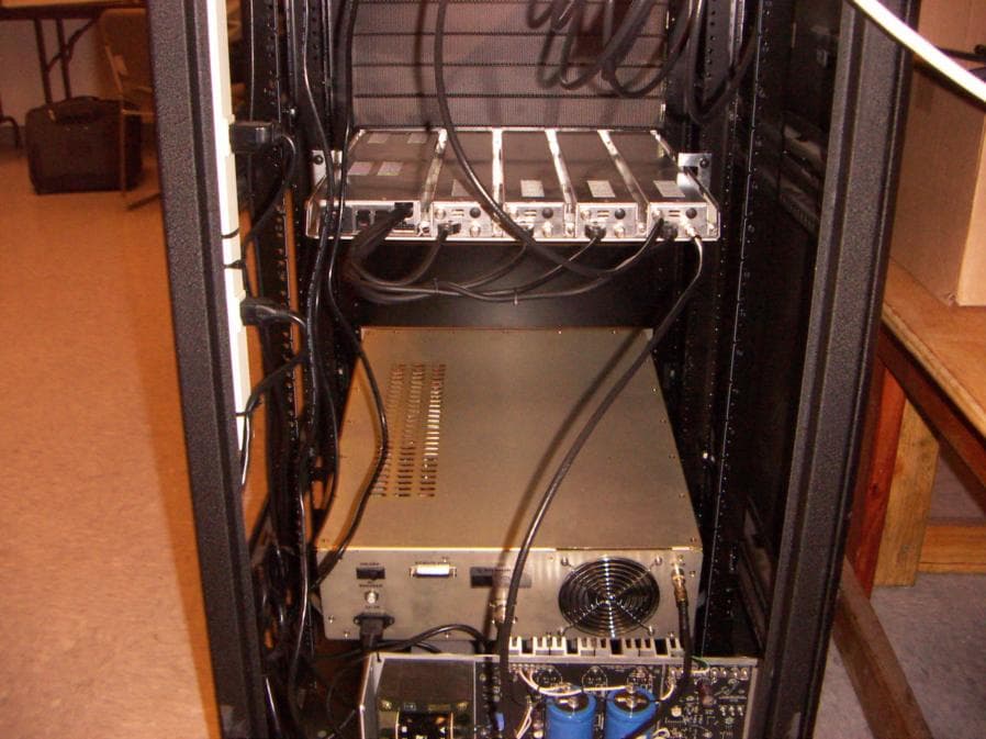
PBJV3000-A
Jan 29, 2006Base Station Transmitter
Equipment Class
TNB - Licensed Non-Broadcast Station Transmitter
PBJV284-PLUS-C
Dec 20, 2005Subscriber WMU
Equipment Class
TNB - Licensed Non-Broadcast Station Transmitter
PBJV284-A
Nov 20, 2005Subscriber WMU
Equipment Class
TNB - Licensed Non-Broadcast Station Transmitter
PBJV284
Nov 14, 2005Subscriber WMU
Equipment Class
TNB - Licensed Non-Broadcast Station Transmitter