PBR-SZG2WCR1G2Z Camera With Access Point
The Kroger Co.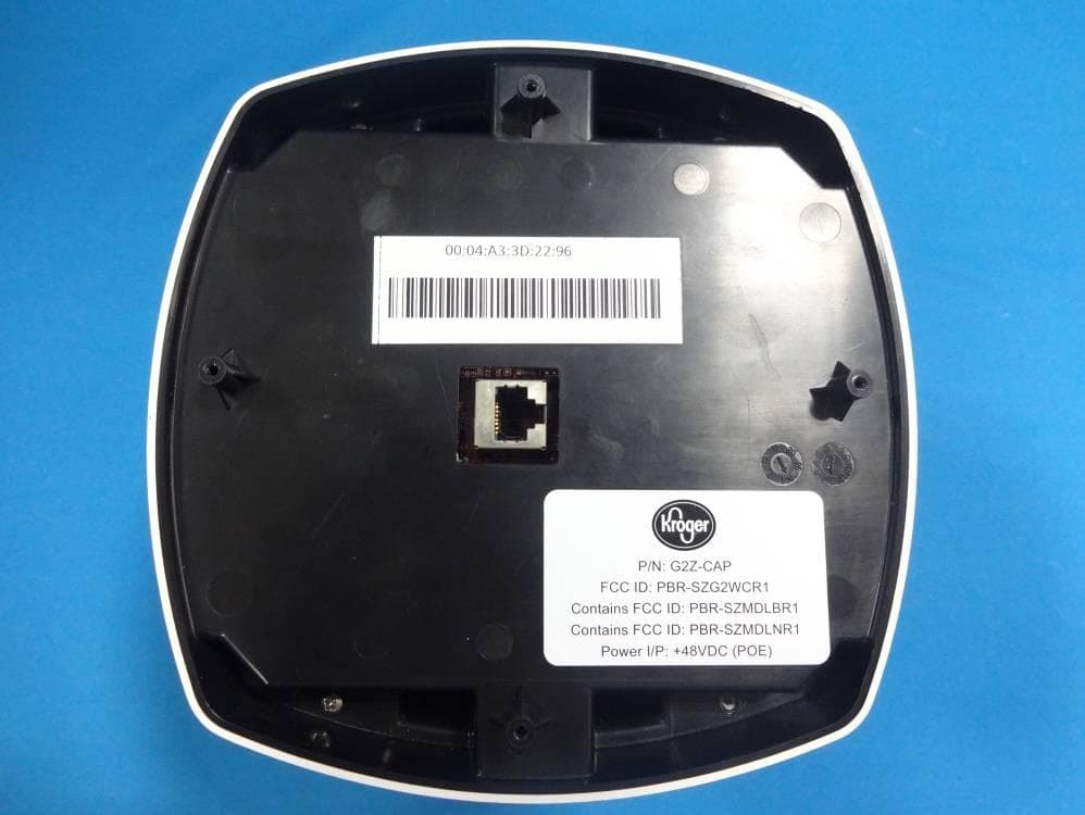
Click to zoom
Application Details
- Equipment Class
- DTS - Digital Transmission System
- Date of Grant
- Nov 26, 2012
- Application Purpose
- Original Equipment
- Date of Application
- Nov 18, 2012
- Equipment Note
- G2Z Camera With Access Point
- Frequency Range
- 2405.00000000 - 2480.00000000
- Company
- The Kroger Co.
- Country
- United States
Documents & Files
Document Text
Text extracted from the exhibit documents filed with the FCC. Open a document above to read the original.
Users Manual
G2Z-CAP Camera User Guide G2Z-CAP User Guide Page 2 The Kroger Co. Release 1.0 Version 1.2 Copyright © 2010, The Kroger Co. All rights reserved. No part of this publication may be reproduced, transmitted, transcribed, stored in a retrieval system, or translated into any language, in any form or by any means, electronic, mechanical, photocopying, recording, or otherwise, without prior written permission from The Kroger Co. All copyright, confidential information, patents, design rights and all other intellectual property rights of whatsoever nature contained herein are and shall remain the sole and exclusive property of The Kroger Co. The information furnished herein is believed to be accurate and reliable. However, no responsibility is assumed by The Kroger Co. for its use, or for any infringements of patents or other rights of third parties resulting from its use. The Kroger Co. name and The Kroger Co. logo are trademarks or registered trademarks of The Kroger Co. All other trademarks are the property of their respective owners. G2Z-CAP User Guide Page 3 Table of Content 1 INTRODUCTION .................................................................................................................5 2 SYSTEM REQUIREMENTS ..................................................................................................6 2.1 SYSTEM REQUIREMENTS ................................................................................................................ 6 3 G2Z-CAP SPECIFICATIONS .................................................................................................7 3.1 PROCESSING ............................................................................................................................... 7 3.2 NETWORK CONNECTIONS .............................................................................................................. 7 3.3 POWER ...................................................................................................................................... 7 3.4 SECURITY ................................................................................................................................... 7 3.5 VIDEO CAPTURE AND ENCODING ..................................................................................................... 7 3.6 CUSTOMER APPLICATIONS ............................................................................................................. 8 3.7 FIRMWARE UPDATES .................................................................................................................... 8 3.8 OPERATING CONDITIONS ............................................................................................................... 8 3.9 DIMENSIONS ............................................................................................................................... 8 3.10 APPROVALS ........................................................................................................................... 8 3.11 INCLUDED ACCESSORIES ........................................................................................................... 8 3.12 SAFETY PRECAUTIONS .............................................................................................................. 8 3.13 ELECTROSTATIC DISCHARGE ...................................................................................................... 8 4 POWER REQUIREMENTS ...................................................................................................9 5 INTERFACE DETAILS ........................................................................................................10 5.1 RS232 INTERFACE: .................................................................................................................... 10 5.2 MICROSD CARD INTERFACE: ........................................................................................................ 10 5.3 USB INTERFACE: ........................................................................................................................ 10 5.4 AUDIO IN/OUT INTERFACE: .......................................................................................................... 10 5.5 ZIGBEE INTERFACE: .................................................................................................................... 10 6 REPLACEABLE BATTERY ...................................................................................................11 7 FCC COMPLIANCE STATEMENTS .....................................................................................11 8 OPERATIONAL INSTRUCTION ..........................................................................................11 Tables Table 1: RJ45 Connector Pin Assignment: 9 G2Z-CAP User Guide Page 4 Revision History Date Change Description Revision 19-SEP-12 Initial Revision 1.0 29-SEP-12 Updated as per Internal Review 1.1 07-Nov-12 Updated for Compliance statements 1.2 G2Z-CAP User Guide Page 5 1 Introduction G2Z-CAP is a PoE powered IP Camera device. It also acts as a wired and wireless access point. Benefits are as follows: Benefits • Built-in Web server that does not require any additional hardware or software to operate • Supports time synchronization with a Network Time Protocol (NTP) server • Ability to view and save snapshots • Ability to Pan/Tilt at 350º and 90º • Access point for ZigBee Infrastructure • Embedded Video Analytics o Customer counting o Dwell Time o Occupancy o Analytics ties in with task management system software. G2Z-CAP User Guide Page 6 2 System Requirements The system requirements for the G2Z-CAP Network Camera include the following for browser- based viewing. 2.1 2.12.1 2.1 System Requirements • Microsoft Windows PC • Microsoft Internet Explorer version 5.x or higher • Apple Quick Time Player G2Z-CAP User Guide Page 7 3 G2Z-CAP Specifications 3.1 3.13.1 3.1 Processing • 600MHz Dual Core SoC • Upto 256MB DDR2 RAM • 128MB NAND FLASH • 3.1M P…
Text truncated - open the document above for the full version.
External Photos
www.tuv.com Appendix 2 Prüfbericht - Nr.: Test Report No. 01200093 001 Seite 1 von 3 Page 1 of 3 EUT Overall View EUT Top View www.tuv.com Appendix 2 Prüfbericht - Nr.: Test Report No. 01200093 001 Seite 2 von 3 Page 2 of 3 EUT Bottom View EUT Dimensional View www.tuv.com Appendix 2 Prüfbericht - Nr.: Test Report No. 01200093 001 Seite 3 von 3 Page 3 of 3 EUT Dimensional View
Internal Photos
www.tuv.com Appendix 2 Prüfbericht - Nr.: Test Report No. 01200093 001 Seite 1 von 3 Page 1 of 3 EUT With Bottom Enclosure Removed EUT With Bottom PCB Removed www.tuv.com Appendix 2 Prüfbericht - Nr.: Test Report No. 01200093 001 Seite 2 von 3 Page 2 of 3 Bottom View Of Internal PCB Top View Of Internal PCB www.tuv.com Appendix 2 Prüfbericht - Nr.: Test Report No. 01200093 001 Seite 3 von 3 Page 3 of 3 Camera PCB
RF Exposure Info
www.tuv.com Appendix 10 Prüfbericht - Nr.: Test Report No. 01200093 001 Seite 1 von 1 Page 1 of 1 Radio Frequency Human Exposure Evaluation: The Highest radiated Power measured was 108.83dBuV/m at 2405MHz when all the modules in the EUT were operating at 2405MHz. 108.83dBuV/m is equivalent to 23mW i.e 13.6dBm The highest RF output power of the EUT was measured below 13.6 dBm at 2405 MHz According to §1.1310 of the FCC rules, the power density limit for General Population/Uncontrolled Exposure at 2480 MHz is 1 mW/cm2. The maximum permissible exposure (MPE) is calculated to show the required separation distance that must be maintained during installation to maintain compliance with the power density limit. The following formula was used to calculate the Power Density: Pd = P * G / (4 * π * R^2) Where: Pd = Power Density P = Output Power at the Antenna Terminals G = Gain of Transmit Antenna (linear gain) R = Distance from Transmitting Antenna To solve for the minimum mounting distance required: R = Sqrt ((P*G) / (4 * π * Pd)) For the EUT, the calculation is as follows: Pd = 0.004578 mW/cm2 P = Output Power = 23 mW G = Worst Case Gain = 1 dBi R = Sqrt ((23 * 1) / (4 * π * 1)) R =1.35 cm (Based on continuous transmission) which is less than 20cm
Test Report
Produkte Products TÜV Rheinland LGA Products GmbH Tillystraße 2 D - 90431 Nürnberg Tel.: +49 911 655 5225 Fax: +49 911 655 5226 Mail: [email protected] Web: www.tuv.com Rev.:1.2 2009-12-29 / approved: M.Jungnitsch Prüfbericht - Nr.: 01200093 001 Seite 1 von 13 Test Report No.: Page 1 of 13 Auftraggeber: Client: The Kroger Co. 11450 Grooms Rd. Blue Ash, OH 45242 United States Gegenstand der Prüfung: Test item: G2Z Camera With Access Point Bezeichnung: Identification: G2Z-CAP Serien-Nr.: Serial No. Engineering Sample Wareneingangs-Nr.: Receipt No.: 1403021239 Eingangsdatum: Date of receipt: 14.08.2012 Prüfort: Testing location: Refer Page 4 of 13 for test facilities Prüfgrundlage: Test specification: FCC Part 15, Subpart C ANSI C63.4-2003 Prüfergebnis: Test Result: Der Prüfgegenstand entspricht oben genannter Prüfgrundlage(n). The test items passed the test specification(s). Prüflaboratorium: Testing Laboratory: TÜV Rheinland (India) Pvt. Ltd. 82/A, 3rd Main, West Wing, Electronic City Phase 1 Hosur Road, Bangalore – 560 100. India geprüft / tested by: kontrolliert / reviewed by: 22.08.2012 Saibaba Siddapur Test Engineer 30.08.2012 Raghavendra Kulkarni Manager Datum Date Name/Stellung Name/Position Unterschrift Signature Datum Date Name/Stellung Name/Position Unterschrift Signature Sonstiges /Other Aspects: FCC ID : PBR-SZG2WCR1 Contains FCC ID:PBR-SZMDLBR1 & PBR-SZMDLNR1 Abkürzungen: P(ass) = entspricht Prüfgrundlage F(ail) = entspricht nicht Prüfgrundlage N/A = nicht anwendbar N/T = nicht getestet Abbreviations: P(ass) = passed F(ail) = failed N/A = not applicable N/T = not tested Dieser Prüfbericht bezieht sich nur auf das o.g. Prüfmuster und darf ohne Genehmigung der Prüfstelle nicht auszugsweise vervielfältigt werden. Dieser Bericht berechtigt nicht zur Verwendung eines Prüfzeichens. This test report relates to the a. m. test sample. Without permission of the test center this test report is not permitted to be duplicated in extracts. This test report does not entitle to carry any safety mark on this or similar products. www.tuv.com Test Report No.: 01200093 001 Date: 22.08.2012 Page 2 of 13 Test Result Summary Clause Test Item Result FCC 15.209 Spurious Radiated Emissions Pass FCC 15.205 Restricted Bands of Operation Pass Note: The Product Contains FCC approved modules and hence the module related tests are excluded. www.tuv.com Test Report No.: 01200093 001 Date: 22.08.2012 Page 3 of 13 Content List of Type and Measurement Instruments ............................................................. 4 General Product Information ..................................................................................... 5 Product Function and Intended Use ............................................................................................. 5 Ratings and System Details ........................................................................................................... 5 Test Set-up and Operation Mode ............................................................................... 6 Principle of Configuration Selection ............................................................................................ 6 Test Operation and Test Software ................................................................................................ 6 Special Accessories and Auxiliary Equipment ............................................................................ 6 Countermeasures to achieve EMC Compliance .......................................................................... 6 Test Methodology ....................................................................................................... 7 Radiated Emission Test ................................................................................................................. 7 Test Results ................................................................................................................. 8 Maximum transmitted output power ............................................................................................ 8 Power Spectral Density .................................................................................................................. 8 Spurious Radiated Emissions and Restricted Bands of Operation Section 15.209 and 15.205 .......................................................................................................................... 9 Appendix 1: Test Setup Photo Appendix 2: EUT External Photo Appendix 3: EUT Internal Photo Appendix 4: FCC Label and Label Location Appendix 5: Block Diagram Appendix 6: Specification of EUT Appendix 7: Schematic Diagrams Appendix 8: Bill of Material Appendix 9: User Manual Appendix 10: Maximum Permissible Exposure Calculation www.tuv.com Test Report No.: 01200093 001 Date: 22.08.2012 Page 4 of 13 List of Type and Measurement Instruments TÜV Rheinland (India) Pvt. Ltd, Bangalore List of Test and Measurement Instruments Equipment Manufacturer Model S/N Calibration Due Date EMI Test Receiver Rohde &Schwarz ESU 40 100288 21.07.2013 Hybrid Log Periodic antenna ETS Lindgren 3142D 00081354 26.07.2013 Broadband Horn Antenna Frankonia HAX-18 HAX18-802 23.03.2013 Double-Ridged Waveguide Horn Antenna ETS Lindgren 116794 00133356 01-09-2013 Emission Horn Antenna ETS Lindgren 116706 00107323 24-08-2013 Active Loop Antenna Frankonia LAX-10 LAX-10-800 11-04-2013 Testing Facilities: 1) TUV Rheinland (India) Private Limited No. 108, West Wing Electronic city Phase I Bangalore – 560100 www.tuv.com Test Report No.: 01200093 001 Date: 22.08.2012 Page 5 of 13 General Product Information Product Function and Intended Use G2Z-CAP is PoE (Power over Ethernet) IP camera, with Pan/Tilt movement and on board ZigBee modules used for wireless communication with other ZigBee devices. G2Z-CAP is ceiling mount device for surveillance and monitoring through network. It captures video from CMOS sensor at different angle (Pan Movement 350º and Tilt Movement 90 º) & streams it…
Text truncated - open the document above for the full version.
Test Setup Photos
www.tuv.com Appendix 1 Prüfbericht - Nr.: Test Report No. 01200093 001 Seite 1 von 3 Page 1 of 3 Test setup Test setup www.tuv.com Appendix 1 Prüfbericht - Nr.: Test Report No. 01200093 001 Seite 2 von 3 Page 2 of 3 Test setup Test setup www.tuv.com Appendix 1 Prüfbericht - Nr.: Test Report No. 01200093 001 Seite 3 von 3 Page 3 of 3 Test setup Test setup
Contact Information
Applicant
Dion Perkins(R&D Engineering Mgr)
Test Firm
TUV Rheinland (India) Pvt. Ltd.,B GURUPRASAD
Technical Specifications
| # | Rule Parts | Frequency Range | Power Output |
|---|---|---|---|
| 1 | 15C | 2.40 GHz - 2.48 GHz | 13.03 mW |
Other Applications from The Kroger Co.
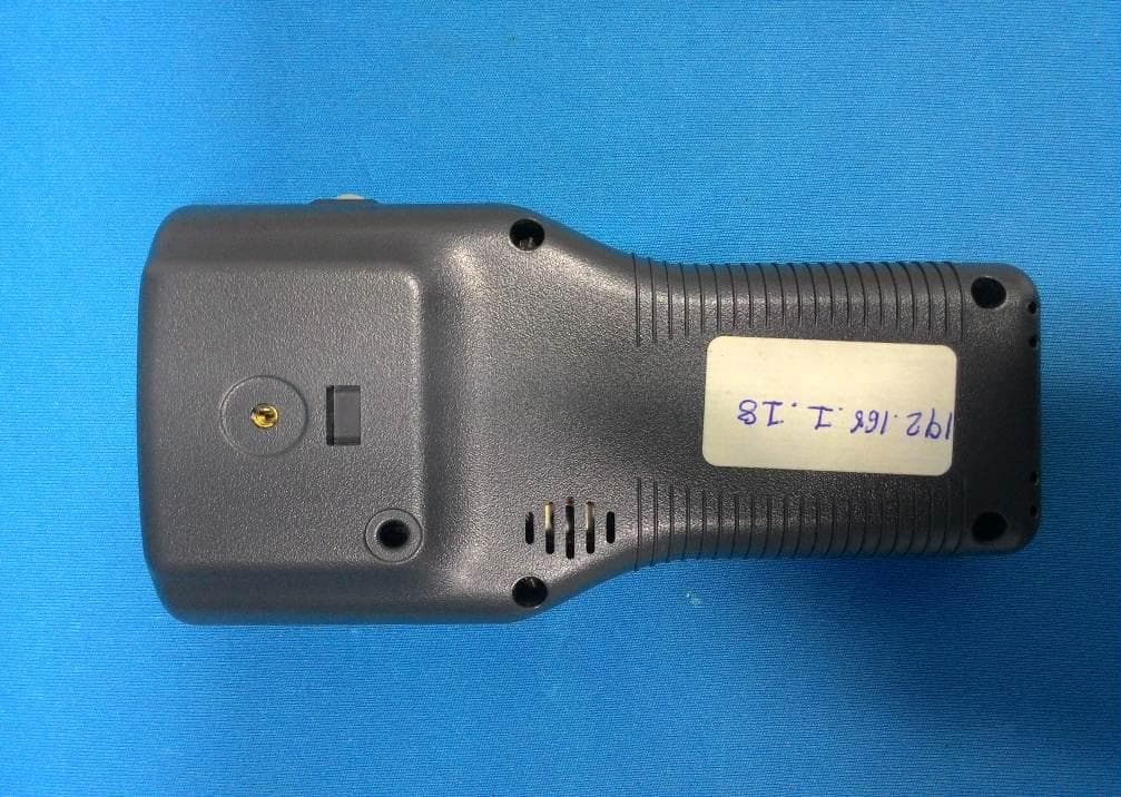
PBR-SZHHG3
Feb 25, 2015CC2530 based ZigBee Scanning Handheld
Equipment Class
DTS - Digital Transmission System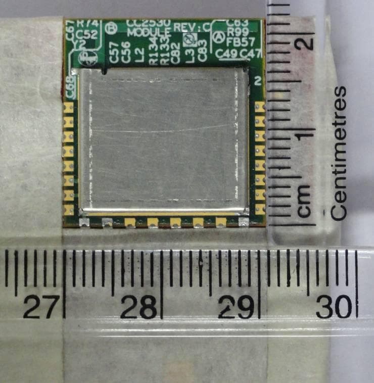
PBR-SZMDLNR1
Oct 30, 2012CC2530 ZigBee Module
Equipment Class
DTS - Digital Transmission System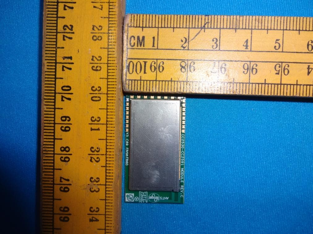
PBR-SZMDLBR1
Oct 30, 2012CC2530-CC2591 ZigBee Module
Equipment Class
DTS - Digital Transmission System