PBY1130401Licensed Portable
Ericsson Mobile Communications AB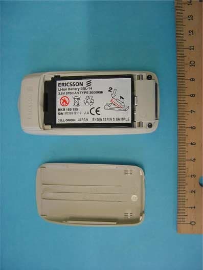
Click to zoom
Application Details
- Equipment Class
- PCE - PCS Licensed Transmitter held to ear
- Date of Grant
- Nov 12, 2001
- Application Purpose
- Original Equipment
- Date of Application
- Sep 02, 2001
- Equipment Note
- Licensed Portable
- Frequency Range
- 1850.20000000 - 1909.80000000
- Country
- Sweden
Documents & Files
Document Text
Text extracted from the exhibit documents filed with the FCC. Open a document above to read the original.
Users Manual
No t f o r Co m m e r c i a l Us e E r i c s s o n M o b i l e Co m m u n i c a t i o n s AB Important batte ry information It takes up t o 30 min utes for a new battery to start charging. Insert the SIM card and attach the battery to the phone before you start charging.Connect the charger to the mains, then to the phone. It takes up to 30 min utes for a new battery to start charging. It takes about 4 hours to fully charge a battery the first time. Disconnect the charger by tilting the plug up. No t f o r Co m m e r c i a l Us e E r i c s s o n M o b i l e Co m m u n i c a t i o n s AB If you have a WAP account for your phone, you can go to Ericsson Mobile Internet and get the WAP settings sent to your phone via SMS. Go to mobileinternet.ericsson.c om and select the brick for WAP and e-mail configuration. Choose to have th e WAP settings sent to your phone, and follow the instructions. To install the new WAP settings 1. When you receive th e text message, press YE S . 2. Select the WAP profile in which you want to save the WAP settings, and press YE S . You can now start using your WAP browser. Easy access to WAP No t f o r Co m m e r c i a l Us e E r i c s s o n M o b i l e Co m m u n i c a t i o n s AB ContentsGetting Started .............................. 5 Making and Rec eiving Calls ......... 8 Key Functions ............................. 12 Using the Menus ......................... 13 Enter ing Letters ........................... 17 Your Per sonal Phone Book ......... 20 Using the Call L ist ...................... 25 Your V oice Mail S ervice ............ 26 Personaliz ing Your Phone ........... 27 Text and Chat Messages ............. 34 Profiles ........................................ 40 Diver ting Incoming Calls ............ 41 Secur ity for Your Phone and Subscription .......................... 42 More Than One Call ................... 46 Setting Network Pref erences .......49 Call Time a nd Call Cost .............. 50 Using the WAP Browser ............. 52 Calendar ............ .......................... 55 Code Memo ................................. 57 Calling Card Calls ....................... 59 Extras ................ .......................... 60 Online Services ........................... 63 Ericsson Mobil e Internet ............. 63 Troubleshootin g .......................... 64 Displ ay Icons ............................... 66 Quick Ke ys .................................. 68 Technical Data ............................ 69 Safe and Efficie nt Use ................. 70 Limited Warr anty ........................ 77 Regulatory Information ............... 79 No t f o r Co m m e r c i a l Us e E r i c s s o n M o b i l e Co m m u n i c a t i o n s AB Ericsson T6 6 First editio n (May 2001) This man ual is published by Ericsso n Mobile Communica tions AB, w ithout any warranty. Improvements and changes to this man ual necessitated by typographical errors, inaccuracies o f current information, or impro vements to programs an d/or equipment, may be made by Ericsso n Mobile Comm unications AB at any time a nd without notice. Suc h changes will, however, be incorporated into new editions of this manual. All rig hts reserved. ©Ericss on Mob ile Communications AB , 2001 Publicatio n number: EN/LZ T 108 4573 R1A INNOVATRON PATENTS Note: Some of the services in this manu al are not supported by all networks. This also app lies to the GSM International Emergency Numb er 112. Note: You shoul d read the Guidelines for Safe and Efficient Use and the Warranty chapters before using your mobile phone. Please contact your network o perator or service provider if you are in doubt whether you can use a particular service or not. T9™ Text Input is a registered trademark of Tegic Commun ications. T9™ Text Input is licensed under one o r more of the following: U.S. Pat. Nos. 5,818,437, 5,953,541, 5,187,480, 5,945,928, and 6,011,554; Canad ian Pat. No. 1,331,057, United Kingdom Pat. No. 2238414B; H ong Kong Standard Pat. No. HK09 40329; R epublic of Singapore Pat. No. 51383; Euro.Pat. No. 0 842 463(96927260.8) DE/DK, FI, FR, IT, NL, PT, ES, SE, GB; and additional patents are pending w orldwide. No t f o r Co m m e r c i a l Us e E r i c s s o n M o b i l e Co m m u n i c a t i o n s AB Getti ng Started 5 Getting StartedFront Back Volume key Display Option key Arrow keys Microphone Indicat or light Earpiece On/off key Keypad Battery cover lid Charging connec tor Handsfree connect or Internal ant enna No t f o r Co m m e r c i a l Us e E r i c s s o n M o b i l e Co m m u n i c a t i o n s AB 6 Getting Started About this User ’s Guide Some services and functions described in this User’s Guide are service provider - and sub scription- dependent. Because of this, all menus may not be available in your phone and the shortcut numbers to menus an d func tions may vary between phones. This symbol indicates that a service or function is ne twork- or service provider dependent. Please refer to the information provided by your service provider for more information about your subscription. We recommend that you read the chapter “Using the Menus” on page 13 for information about how to move through the men us. The SIM Card When you register as a subscriber with a network operator, you get a SIM (Subscriber Identity Module) card. The SIM card contains a co mputer chip that keeps track of your phone number, the services included in your subscription, and your Phone book information, among other things. SIM cards come in two sizes. One is the size of a credit card and the other is smaller. Your phone uses the smaller card. Many credit card-sized SIM cards have a perforated smaller card that you can take out easily. Assemb ly Before you can use your phone you need to: • insert the SIM car d. Note: Always insert the SIM ca rd into the phone before attaching the battery. • attach and charge the battery. Note: Always turn off the phon e and detach the charger before you insert or remove a SIM card. No t f o r Co m m e …
Text truncated - open the document above for the full version.
External Photos
CETECOM ICT Services GmbH Test report nr.: 4-0409-A/01 Issue date:03.08.2001 Page 47 (56) Photographs of the equipment Photograph no.: 1 CETECOM ICT Services GmbH Test report nr.: 4-0409-A/01 Issue date:03.08.2001 Page 48 (56) Photographs of the equipment Photograph no.: 2 CETECOM ICT Services GmbH Test report nr.: 4-0409-A/01 Issue date:03.08.2001 Page 49 (56) Photographs of the equipment Photograph no.: 3 CETECOM ICT Services GmbH Test report nr.: 4-0409-A/01 Issue date:03.08.2001 Page 50 (56) Photographs of the equipment Photograph no.: 4 CETECOM ICT Services GmbH Test report nr.: 4-0409-A/01 Issue date:03.08.2001 Page 51 (56) Photographs of the equipment Photograph no.: 5
ID Label/Location Info
Limited Internal DESCRIPTION1 (1) Prepared (also subject responsible if other)No. LD/ECS/GUP/NV Håkan Sjöberg +46 46 193559GTP/NV01:262 Uen ApprovedCheckedDateRevReference LD/ECS/GUP/NVC Bo Johansson2001-09-04A Application PBY1130401 Exhibit 1: ID Label and Location Info The ID label is placed under the battery pack at the back of the phone (according to photo below). Placement of ID Label
Internal Photos
CETECOM ICT Services GmbH Test report nr.: 4-0409-A/01 Issue date:03.08.2001 Page 52 (56) Photographs of the equipment Photograph no.: 6 CETECOM ICT Services GmbH Test report nr.: 4-0409-A/01 Issue date:03.08.2001 Page 53 (56) Photographs of the equipment Photograph no.: 7 CETECOM ICT Services GmbH Test report nr.: 4-0409-A/01 Issue date:03.08.2001 Page 54 (56) Photographs of the equipment Photograph no.: 8 CETECOM ICT Services GmbH Test report nr.: 4-0409-A/01 Issue date:03.08.2001 Page 55 (56) Photographs of the equipment Photograph 9: CETECOM ICT Services GmbH Test report nr.: 4-0409-A/01 Issue date:03.08.2001 Page 56 (56) Photographs of the equipment Photograph 10:
Internal Photos
Limited Internal DESCRIPTION 1 (2) Prepared (also subject responsible if other) No. LD/SEM/GUG/NV Håkan Sjöberg +46 46193559 GTP/NV01:313 Uen Approved Checked Date Rev Reference LD/SEM/GUG/NVC Bo Johansson 2001-10-31 A Application PBY1130401 Exhibit: Photo of internal antenna The internal antenna is placed on the inside of the back top cover according to pictures below. Internal antenna Limited Internal DESCRIPTION 2 (2) Prepared (also subject responsible if other) No. LD/SEM/GUG/NV Håkan Sjöberg +46 46193559 GTP/NV01:313 Uen Approved Checked Date Rev Reference LD/SEM/GUG/NVC Bo Johansson 2001-10-31 A Internal antenna on the inside of the top back cover
RF Exposure Info
Confidential REPORT 1 (16) Prepared (also subject responsible if other)No. LD/ECS/GUF/KG Ramadan Plicanic GTX/FG 01:066 ApprovedCheckedDateRevFile GUF/KG Ramadan PlicanicECSRAPL2001-09-03A H:\RR\SAR_FCC Report\T66.doc EN SAR Test Report: T66 Date of test:August 16,17 and 20, 2001 Laboratory: Electromagnetic Near Field and Radio Frequency Dosimetry Laboratory Ericsson Mobile Communications AB Nya Vattentornet, SE-221 83 LUND, Sweden Test Responsible: Ramadan Plicanic, M.Sc.EE Senior Staff Engineer, Terminal Antennas [email protected] +46 46 19 38 62 Statement of Compliance Ericsson Mobile Communications AB declares under its sole responsibility that the that the product Ericsson Type 1130401-BV (T66) to which this declaration relates, is in conformity with the appropriate RF exposure standards, recommendations and guidelines. It also declares that the product was tested in accordance with the appropriate measurement standards, guidelines and recommended practices. Any deviations from these standards, guidelines and recommended practices are noted below: (none) © Ericsson Mobile Communications AB, 2001 This test report shall not be reproduced except in full, without written approval of the laboratory. The results and statements contained herein relate only to the items tested. The names of individuals involved may be mentioned only in connection with the statements or results from this report. Ericsson encourages all feedback, both positive and negative, on this test report. Confidential REPORT 2 (16) Prepared (also subject responsible if other)No. LD/ECS/GUF/KG Ramadan Plicanic GTX/FG 01:066 ApprovedCheckedDateRevFile GUF/KG Ramadan PlicanicECSRAPL2001-09-03A H:\RR\SAR_FCC Report\T66.doc EN Table of Contents 1. Introduction3 2. Device Under Test3 2.1Antenna description3 2.2Device description3 3. Test equipment3 3.1 Dosimetric system3 3.2Additional equipment3 4. Electrical parameters of the tissue simulating liquid4 5. System accuracy verification4 6. Test results5 References6 Appendix 1: SAR distribution comparison for system accuracy verification7 Appendix 2: SAR distribution plots9 Appendix 3: Photographs of the device under test12 Appendix 4: Position of device on Generic Twin Phantom14 Appendix 5: Probe calibration parameters for ET3DV6 SN:156916 Confidential REPORT 3 (16) Prepared (also subject responsible if other)No. LD/ECS/GUF/KG Ramadan Plicanic GTX/FG 01:066 ApprovedCheckedDateRevFile GUF/KG Ramadan PlicanicECSRAPL2001-09-03A H:\RR\SAR_FCC Report\T66.doc EN 1. Introduction In this test report, compliance of the Ericsson T66 portable telephone with RF safety guidelines is demonstrated (applicable RF safety guidelines are given in [1]). The device was tested in accordance with the latest available test guidelines [1]. Detailed procedures of the test are described in the Ericsson SAR Measurement Specification [2]. 2. Device Under Test 2.1 Antenna description Type Built in Location Back on the top length- Dimensions width at base- Configuration PIFA 2.2 Device description Device model T66 Serial numberBLU100005456 Mode 1900 TDMA Multiple Access Scheme TDMA Maximum Output Power Setting 1 29.0 dBm Factory Tolerance in Power Setting ± 0.5dB Maximum Peak Output Power 2 29.5 dBm Duty Cycle1 / 8 Transmitting Frequency Range1850 – 1910 MHz Prototype or Production UnitPrototype 3. Test equipment 3.1 Dosimetric system SAR measurements were made using the DASY3 professional system (software version 3.1c), manufactured by Schmid & Partner Engineering AG and installed Juny, 1996. The total SAR assessment uncertainty (K = 1) of the system is ±16% and includes a +15% offset (overestimation). The extended uncertainty (K = 2) is ±32% with a +15% offset. This results in a total uncertainty range of –1% to +31% for K = 1, or –17% to +47% for K = 2. The equipment list is given below. DescriptionSerial NumberDue Date DASY3 DAE V2 2155/02 E-field probe ETDV615695/02 Dipole Validation Kit, D1800V22285/03 1 This is the conducted power measured at the antenna port when the device is set to its highest power setting. It is measured at the middle of the transmit frequency band. Note that the output power may be different at other frequencies. 2 This equals the maximum output power setting plus the factory tolerance. Confidential REPORT 4 (16) Prepared (also subject responsible if other)No. LD/ECS/GUF/KG Ramadan Plicanic GTX/FG 01:066 ApprovedCheckedDateRevFile GUF/KG Ramadan PlicanicECSRAPL2001-09-03A H:\RR\SAR_FCC Report\T66.doc EN 3.2 Additional equipment DescriptionSerial NumberDue Date Signal Generator ESG-D4000A INV 5629354/02 Dielectric probe kit HP 85070B INV 4430297/02 Network analyzer HP 8753CINV 4216706/02 Power meter R&S NRVDINV 48392012/01 Power sensor R&S NRV-Z5INV 233412/01 Wavetek 4106GPPINV 4629917/02 4. Electrical parameters of the tissue simulating liquid Prior to conducting SAR measurements, the relative permittivity, ε r , and the conductivity, σ, of the tissue simulating liquids were measured with the dielectric probe kit. These values are shown in the table below. The mass density, ρ, entered into the DASY3 program is also given. Recommended limits for maximum permittivity, minimum conductivity and maximum mass density are also shown [3]. It is seen that the measured parameters result in an overestimation of SAR compared to the recommended values. Dielectric Parameters f (MHz) Tissue type Limits / Measured ε r σ (S/m)ρ (g/cm 3 ) Measured, 08/14/01 39.4 1.651.00Head Recommended Limits[3]40.01.41.03 Measured, 08/14/0139.41.681.00 1800 Muscle Recommended Limits [3]53.31.521.04 5. System accuracy verification A system accuracy verification of the DASY3 was performed using the dipole validation kit listed in Section 3.1. The system verification test was conducted on the same day as the measurement of the DUT. The obtained results are displayed in the table below. It is seen that the system is operating within its specification, as the results are within ±5% of the reference va…
Text truncated - open the document above for the full version.
RF Exposure Info
Uppgjord -Prepared ERA/T/F Martin Siegbahn Godkänd -Approved ERA/T/FC (Christer Törnevik) Kontr. -Checked Datum -Date 2000-11-13 Ert datum -Your date Rev A Dokumentnr -Document no T/F 00:037 Blad -Sheet 1 (1) Tillhör referens -File/reference Tfn -Telephone 75-70811 Dokument -Document Document list INTERNAL LIMITED Ericsson SAR Measurement Specification PartDocument nameDocument numberRev 1Introduction and purposeERA/T/U-98:446C 2Tissue liquid preparationERA/T/F-00:032A 3Measurements of dielectric parametersERA/T/U-98:405F 4System accuracy verificationEUS/TR/X-98:1585F 5Calibration of equipmentEUS/TR/X-98:1586D 6DUT preparation and characterizationERA/T/U-98:439I 7SAR measurement procedureERA/T/U-98:441J 8Documentation of resultsERA/T/U-98:447C 9BibliographyERA/T/U-99:047D 10Glossary of symbolsEUS/TR/X-99:1336A Internal limited INSTRUCTION1 (4) Uppgjord (även faktaansvarig om annan) - Prepared (also subject responsible if other)Nr - No. ERA/T/UF Christer TörnevikT/U-98:446 Dokansv/Godk – Doc respons/ApprovedKontr - CheckedDatum - Date RevFile ERA/T/UF Christer Törnevik2000-03-17C Ericsson SAR measurement specification, part 1: Introduction and purpose 1. Introduction It is an Ericsson policy that all RF transmitting products shall comply with existing recommendations, standards and regulations on human exposure to electromagnetic fields. In the reference section below, the most important RF safety guidelines are listed [1-8]. If no national standard or regulation is available in a country, the international recommendation from ICNIRP [1] shall be applied for Ericsson products. The RF safety guidelines specify basic restrictions and reference levels. In the frequency range of interest for mobile communications, the basic restrictions are expressed as Specific Absorption Rate (SAR) limits and the reference levels as field strength or power density limits. The reference levels are provided for the purpose of simple measurements of compliance with the basic restrictions, and they are primarily applicable in the farfield region of a RF source. Measured values greater than the reference levels do not necessarily mean that the basic restrictions are exceeded. In the nearfield region of mobile communication devices (handsets or base station antennas), field strength values exceeding the reference levels may be observed. Compliance with the basic SAR restrictions has therefor to be verified. SAR (W/kg) is a measure of the rate of RF energy absorption in tissue. The table below shows the localized SAR limits for the general public (uncontrolled environment) and workers (controlled environment) in the ICNIRP and ANSI/IEEE guidelines. Mobile communication equipment are usually used by the general public and should consequently be in compliance with the general public limits, which are 2.0 W/kg averaged in 10 gram of tissue in the ICNIRP guidelines and 1.6 W/kg averaged in 1 gram in the ANSI/IEEE standard. Because of the lower limit and the smaller averaging mass, the ANSI/IEEE limit is slightly more conservative than the ICNIRP limit. The averaging times are also different, 6 minutes in the ICNIRP recommendations and 30 minutes in the IEEE guidelines. The 2.0 W/kg (10 g) SAR limit has also been adopted in a European Prestandard from CENELEC [3] and in guidelines from the Ministry of Post and Telecommunications in Japan [4]. The 1.6 W/kg (1g) SAR limit has been adopted by the FCC as a regulation in the U.S. [6], and also as the basic restriction in preliminary Australian and Canadian standards [5,6]. The FCC requires SAR testing of mobile phones since 1997 [6,10]. Similar requirements were introduced in Australia February 1, 1999 [7] and will be introduced in Canada during 1999. In Europe and Japan regulations are expected within the next few years. SAR test standards for mobile communication equipment are under development by IEC, CENELEC, IEEE and ARIB. In the year 2000, it is expected that the first international standard will be published. Technical documents describing SAR test methods and procedures are already available from CENELEC, ARIB, ACA and the FCC [7-10]. Standard/GuidelineLocalized SAR limit (W/kg) General public (uncontrolled) Localized SAR limit (W/kg) Workers (controlled) ICNIRP (1998)2.0 (10 g)10 (10 g) ANSI/IEEE (1992)1.6 (1 g)8.0 (1g) Internal limited INSTRUCTION2 (4) Uppgjord (även faktaansvarig om annan) - Prepared (also subject responsible if other)Nr - No. ERA/T/UF Christer TörnevikT/U-98:446 Dokansv/Godk – Doc respons/ApprovedKontr - CheckedDatum - Date RevFile ERA/T/UF Christer Törnevik2000-03-17C 2. Purpose of the Ericsson SAR measurement specification The purpose of the Ericsson SAR measurement specification is to describe how SAR tests shall be conducted in the three SAR test laboratories in Ericsson, which are: • The Ericsson EMF Research Laboratory at Ericsson Research in Kista (Contacts: ERA/T/UF Christer Törnevik or ERA/T/UD Martin Siegbahn) • The ECS SAR laboratory at Ericsson Mobile Communications in Lund (Contacts: ECS/TN/FAC Thomas Bolin or ECS/TA/FA Ramadan Plicanic) • The EUS SAR laboratory at Ericsson Inc. in RTP (Contacts: EUS Russ Holshouser or EUS Mark Douglas) All these laboratories are equipped with the DASY3 SAR test system from Schmid & Partner Engineering AG (SPEAG). Since there is not yet an official standard that defines and describes SAR test procedures, it is necessary to specify internal Ericsson procedures for testing of mobile communication equipment. When an international SAR test standard is available, the Ericsson SAR measurement specification will be partly or completely replaced by this standard. The Ericsson SAR measurement specification may be submitted to agencies like the FCC (USA), ACA (Australia) and Industry Canada if requested. 3. Applicability of the Ericsson SAR measurement specification The Ericsson SAR test measurement specification shall always be followed when testing for compliance with SAR limits for handheld radio products …
Text truncated - open the document above for the full version.
RF Exposure Info
T66 SAR plots for all 18 measurements and Z axis scan data for all 18 measurements • 1850MHz • 1880 MHz • 1910 MHz
Test Report
CETECOM ICT Services GmbH Radio Satellite Communication Untertürkheimer Straße 6-10 . D-66117 Saarbrücken Telefon: +49 (0)681 598-9100 Telefax: -9075 RSC11 issue test report consist of 56 Pages Page 1 (56) Test report no.:4-0409-A/01 FCC Part 24 1130401-BV FCC-ID: PBY1130401 Accredited Testing Laboratory DAR-Registration number: TTI-P-G 166/98-00 CETECOM ICT Services GmbH Test report nr.: 4-0409-A/01 Issue date:03.08.2001 Page 2 (56) Table of Contents 1 General information 1.1 Notes 1.2 Testing laboratory 1.3 Details of applicant 1.4 Application details 1.5 Test item 1.6 Test standards 2 Technical test 2.1 Summary of test results 2.2 Test report 1 General information 1.1 Notes The test results of this test report relate exclusively to the test item specified in 1.5. The CETECOM ICT Services GmbH does not assume responsibility for any conclusions and generalisations drawn from the test results with regard to other specimens or samples of the type of the equipment represented by the test item. The test report may only be reproduced or published in full. Reproduction or publication of extracts from the report requires the prior written approval of the CETECOM ICT Services GmbH. 1.2 Testing laboratory CETECOM ICT Services GmbH Untertürkheimer Straße 6 - 10 66117 Saarbrücken Germany Telefone : + 49 681 598 - 0 Telefax : + 49 681 598 - 9075 E-mail : [email protected] Internet : www.cetecom.de Accredited testing laboratory DAR-registration number : TTI-P-G 166/98-00 CETECOM ICT Services GmbH Test report nr.: 4-0409-A/01 Issue date:03.08.2001 Page 3 (57) 1.3 Details of applicant Name : Ericsson Mobile Communications AB Street : Nya Vattentornet City : S-22183 Lund Country : Sweden Telephone : +46-46-19 3000 Telefax : +46-46-19 3295 Contact : Mr. Bo Johansson Telephone : +46-46-19 3000 1.4 Application details Date of receipt of application : 01.08.01 Date of receipt of test item : 01.08.01 Date of test : 01. – 03.08.01 1.5 Test item Type of equipment : GSM 900/1800/1900 Mobile Phone Type designation : 1130401-BV Manufacturer : applicant Street : City : Country : Serial number : BLU100004586 Additional informations: : Frequency : 1850 - 1910 MHz Type of modulation : 300KF2D Number of channels : 300 Antenna : integral antenna and socket Power supply : 3.6 VDC accu Li-Polymer Output power : 28.6 dBm Peak cond./ ERP : 24.5 dBm (Burst); EIRP: 26.6 dBm (Burst) Type of equipment : Temperature range : -30°C - +60°C FCC – ID : PBY1130401 Hardware : 2.902 Software : 0.210 1.6 Test standards: FCC Part 24 CETECOM ICT Services GmbH Test report nr.: 4-0409-A/01 Issue date:03.08.2001 Page 4 (56) 2 Technical test 2.1 Summary of test results No deviations from the technical specification(s) were ascertained in the course of the tests performed. FINAL VERDICT: PASS Technical responsibility for area of testing : 03.09.01 RSC 8411 Berg M. Date Section Name Signature Technical responsibility for area of testing : 03.09.01 RSC8414 Ames Date Section Name Signature CETECOM ICT Services GmbH Test report nr.: 4-0409-A/01 Issue date:03.08.2001 Page 5 (56) 2.2 Testreport TEST REPORT Testreport no. : 4-0409-A/01 CETECOM ICT Services GmbH Test report nr.: 4-0409-A/01 Issue date:03.08.2001 Page 6 (56) TEST REPORT REFERENCE LIST OF MEASUREMENTS PARAMETER TO BE MEASURED Paragraph PAGE POWER OUTPUT SUBCLAUSE § 24.232 7 FREQUENCY STABILITY SUBCLAUSE § 24.235 9 EMISSIONS LIMITS §24.238 11 CONDUCTED SPURIOUS EMISSIONS 27 OCCUPIED BANDWIDTH §2.989 36 CONDUCTED EMISSIONS § 15.107/207 40 TEST EQUIPMENT AND ANCILLARIES USED FOR TESTS 41 TEST SITE 43 PHOTOGRAPHS OF THE EQUIPMENT 47 CETECOM ICT Services GmbH Test report nr.: 4-0409-A/01 Issue date:03.08.2001 Page 7 (56) REFERENCE NUMBER(S) OF TEST EQUIPMENT USED (for reference numbers see test equipment listing) 64 POWER OUTPUT SUBCLAUSE § 24.232 Summery: This paragraph contains both average , peak output powers and EIRP measurements for the mobile station. In all cases, the peak output power is wthin the required mask (this mask is specified in the JTC standarts, TIA PN3389 Vol. 1 Chap 7, and is no FCC requirement). Method of Measurements: The mobile was set up for the max. output power with pseudo random data modulation. The power was measured with R&S Spectrum Analyzer FSIQ 26 ( peak and average) This measurements were done at 3 frequencies, 1850,2 MHz, 1880,0 MHz and 1909,8 MHz (bottom, middle and top of operational frequency range) Limits: Power Step Nominal Peak Output Power (dBm) Tolerance (dB) 0 +30 ± ±± ± 2 Power Measurements: Conducted: Frequency (MHz) Power Step Peak Output Power (dBm) Average Output Power (dBm) 1850.2 0 28.6 19.6 1880.0 0 28.2 19.2 1909.8 0 28.2 19.2 Measurement uncertainty ± ±± ±0.5 dB CETECOM ICT Services GmbH Test report nr.: 4-0409-A/01 Issue date:03.08.2001 Page 8 (56) REFERENCE NUMBER(S) OF TEST EQUIPMENT USED (for reference numbers see test equipment listing) 17 - 24 EIRP Measurements Description: This is the test for the maximum radiated power from the phone. Rule Part 24.232(b) specifies that "Mobile/portable stations are limited to 2 watts e.i.r.p. peak power..." and 24.232(c) specifies that "Peak transmit power must be measured over any interval of continuous transmission using instrumentation calibrated in terms of an rms-equivalent voltage." Method of Measurement: 1. In an anechoic antenna test chamber, a half-wave dipole antenna for the frequency band of interest is placed at the reference center of the chamber. An RF Signal source for the frequency band of interest is connected to the dipole with a cable that has been constructed to not interfere with the radiation pattern of the antenna. A known (measured) power (Pin) is applied to the input of the dipole, and the power received (Pr) at the chamber's probe antenna is recorded. 2. A "reference path loss" is established as Pin + 2.1 - Pr. 3. The EUT is substituted for the dipole at the reference center of the chamber. The EUT is put into CW test mode and a scan is performed to obtain the …
Text truncated - open the document above for the full version.
Test Setup Photos
CETECOM ICT Services GmbH Test report nr.: 4-0409-A/01 Issue date:03.08.2001 Page 43 (56) Test site RADIATED EMISSIONS CETECOM ICT Services GmbH Test report nr.: 4-0409-A/01 Issue date:03.08.2001 Page 44 (56) Test site RADIATED EMISSIONS CETECOM ICT Services GmbH Test report nr.: 4-0409-A/01 Issue date:03.08.2001 Page 45 (56) Test site RADIATED EMISSIONS CETECOM ICT Services GmbH Test report nr.: 4-0409-A/01 Issue date:03.08.2001 Page 46 (56) Test site RADIATED EMISSIONS
Contact Information
Applicant
Mats Hansson(Senior Staff Engineer)
Technical Contact
Ericsson Mobile Communications ABH�kan Sj�berg
[email protected]+4646193000
Im Teelbruch 122 · Lund · Germany
Non-Technical Contact
Ericsson Mobile Communications ABMats Hansson
[email protected]+4646193000
Test Firm
Cetecom ICT Services GmbHRalf Hoehn
Technical Specifications
| # | Rule Parts | Frequency Range | Power Output | Emission | Tolerance |
|---|---|---|---|---|---|
| 1 | 24E | 1.85 GHz - 1.91 GHz | 457.00 mW | 291KDXW | 0.0700000000 ppm |
Other Applications from Ericsson Mobile Communications AB

PBY6130201-BV
Nov 25, 2001PCMCIA card for Laptop Computer
Equipment Class
TNB - Licensed Non-Broadcast Station Transmitter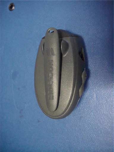
PBY8505002
Sep 27, 2001Bluetooth Headset
Equipment Class
DSS - Part 15 Spread Spectrum Transmitter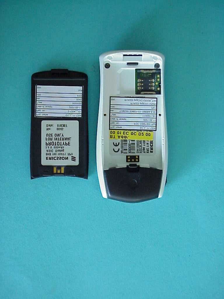
PBY1130201
Jul 10, 2001Licensed Portable
Equipment Class
PCE - PCS Licensed Transmitter held to ear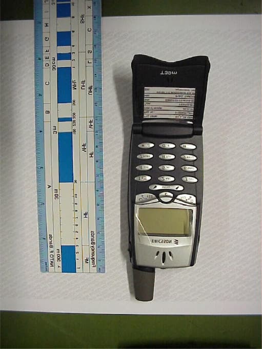
PBY1130102
May 10, 2001Licensed Portable
Equipment Class
PCE - PCS Licensed Transmitter held to ear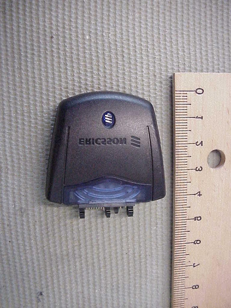
PBY8404003-BV
Mar 22, 2001Bluetooth Phone Plug
Equipment Class
DSS - Part 15 Spread Spectrum Transmitter