PD913100NGWiGig Docking Module
Intel Corporation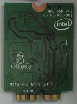
Click to zoom
Application Details
- Equipment Class
- DXT - Part 15 Low Power Transceiver, Rx Verified
- Date of Grant
- Oct 28, 2014
- Application Purpose
- Original Equipment
- Date of Application
- Oct 27, 2014
- Equipment Note
- WiGig Docking Module
- Frequency Range
- 58320.00000000 - 62640.00000000
- Company
- Intel Corporation
- Country
- France
Documents & Files
Document Text
Text extracted from the exhibit documents filed with the FCC. Open a document above to read the original.
Users Manual
Intel ® Maple Peak User Guide July 2014 Revision 2.1 Intel Confidential Document Number: 537178-2.1 Notice: This document contains information on products in the design phase of development. The information here is subject to change without notice. Do not finalize a design with this information. INFORMATION IN THIS DOCUMENT IS PROVIDED IN CONNECTION WITH INTEL PRODUCTS. NO LICENSE, EXPRESS OR IMPLIED, BY ESTOPPEL OR OTHERWISE, TO ANY INTELLECTUAL PROPERTY RIGHTS IS GRANTED BY THIS DOCUMENT. EXCEPT AS PROVIDED IN INTEL’S TERMS AND CONDITIONS OF SALE FOR SUCH PRODUCTS, INTEL ASSUMES NO LIABILITY WHATSOEVER AND INTEL DISCLAIMS ANY EXPRESS OR IMPLIED WARRANTY, RELATING TO SALE AND/OR USE OF INTEL PRODUCTS INCLUDING LIABILITY OR WARRANTIES RELATING TO FITNESS FOR A PARTICULAR PURPOSE, MERCHANTABILITY, OR INFRINGEMENT OF ANY PATENT, COPYRIGHT OR OTHER INTELLECTUAL PROPERTY RIGHT. A "Mission Critical Application" is any application in which failure of the Intel Product could result, directly or indirectly, in personal injury or death. SHOULD YOU PURCHASE OR USE INTEL’S PRODUCTS FOR ANY SUCH MISSION CRITICAL APPLICATION, YOU SHALL INDEMNIFY AND HOLD INTEL AND ITS SUBSIDIARIES, SUBCONTRACTORS AND AFFILIATES, AND THE DIRECTORS, OFFICERS, AND EMPLOYEES OF EACH, HARMLESS AGAINST ALL CLAIMS COSTS, DAMAGES, AND EXPENSES AND REASONABLE ATTORNEYS' FEES ARISING OUT OF, DIRECTLY OR INDIRECTLY, ANY CLAIM OF PRODUCT LIABILITY, PERSONAL INJURY, OR DEATH ARISING IN ANY WAY OUT OF SUCH MISSION CRITICAL APPLICATION, WHETHER OR NOT INTEL OR ITS SUBCONTRACTOR WAS NEGLIGENT IN THE DESIGN, MANUFACTURE, OR WARNING OF THE INTEL PRODUCT OR ANY OF ITS PARTS. Intel may make changes to specifications and product descriptions at any time, without notice. Designers must not rely on the absence or characteristics of any features or instructions marked “reserved” or “undefined.” Intel reserves these for future definition and shall have no responsibility whatsoever for conflicts or incompatibilities arising from future changes to them. The information here is subject to change without notice. Do not finalize a design with this information. Intel software products are copyrighted by and shall remain the property of Intel Corporation. Use, duplication, or disclosure is subject to restrictions stated in Intel’s Software License Agreement, or in the case of software delivered to the government, in accordance with the software license agreement as defined in FAR 52.227-7013. The products described in this document may contain design defects or errors known as errata which may cause the product to deviate from published specifications. Current characterized errata are available on request. The code names presented in this document are only for use by Intel to identify products, technologies, or services in development that have not been made commercially available to the public, i.e., announced, launched, or shipped. They are not "commercial" names for products or services and are not intended to function as trademarks. Contact your local Intel sales office or your distributor to obtain the latest specifications and before placing your product order. Copies of documents which have an order number and are referenced in this document, or other Intel literature may be obtained by calling 1-800-548-4725 or by visiting Intel’ s website at http://www.intel.com/design/literature.htm. Intel is a trademark of Intel Corporation or in the US and other countries. * Other brands and names may be claimed as the property of others. Copyright © 2014 Intel Corporation. All rights reserved. Intel ® Maple Peak July 2014 User Guide Document Number: 537178-2.1 2 Intel Confidential Contents 1 Introduction ................................................................................................................. 6 1.1 Scope ................................................................................................................. 6 1.2 References .......................................................................................................... 6 1.3 Introduction ......................................................................................................... 6 1.3.1 Wireless docking .................................................................................. 6 1.3.2 Wireless peripheral .............................................................................. 7 1.3.3 Multi Gbps Device-to-Device.................................................................. 7 1.4 Key features ........................................................................................................ 7 1.5 SW and HW deliverables ........................................................................................ 7 1.6 Notebook platform preparations for WiDock ............................................................. 7 1.7 Known limitations ................................................................................................. 7 2 Maple Peak Setup ......................................................................................................... 8 2.1 Operational mode ................................................................................................. 8 2.1.1 IF setup description (dock installer only) ................................................. 8 2.1.2 RF setup description ............................................................................. 9 2.2 Test mode (OEM tool setup environment) ................................................................ 9 3 Software Install .......................................................................................................... 11 3.1 NB side installation .............................................................................................. 11 3.2 Dock side installation ........................................................................................... 12 3.2.1 Overview .......................................................…
Text truncated - open the document above for the full version.
Cover Letter(s)
100 Center Point Circle Columbia, SC 29210 October 20, 2014 Subject: Confidentiality Request for FCC ID: PD913100NG Pursuant to FCC 47 CRF 0.457(d) and 0.459 the applicant requests that a part of the subject FCC application be held confidential. Type of Confidentiality Requested Exhibit Short Term Permanent Block Diagrams Short Term External Photos Short Term Permanent Internal Photos Short Term Permanent Operation Description/WiGig Antenna Specification Short Term Permanent Operation Description/HW Theory of Operation Short Term Permanent Schematics Short Term Test Setup Photos Short Term Permanent User’s Manual Intel Mobile Communications has spent substantial effort in developing this product and it is one of the first of its kind in industry. Having the subject information easily available to "competition" would negate the advantage they have achieved by developing this product. Not protecting the details of the design will result in financial hardship. Permanent Confidentiality: The applicant requests the exhibits listed above as permanently confidential be permanently withheld from public review due to materials that contain trade secrets and proprietary information not customarily released to the public. Short-Term Confidentiality: The applicant requests the exhibits selected above as short term confidential be withheld from public view for a period of 180 days from the date of the Grant of Equipment Authorization and prior to marketing. This is to avoid premature release of sensitive information prior to marketing or release of the product to the public. Applicant is also aware that they are responsible to notify ACB in the event information regarding the product or the product is made available to the public. ACB will then release the documents listed above for public disclosure pursuant to FCC Public Notice DA 04-1705. Sincerely, Steven C. Hackett By: __________________________ ________________________ (Signature/Title 1 ) (Print Name)
Cover Letter(s)
Intel Corporation 100 Center Point Circle Columbia, SC 29210 Modular Approval Requirements Attestation FCC ID: PD913100NG Modular Approval is being requested for this device under the ID’s listed above. This device is a self contained, physically delineated, component for which compliance was demonstrated independent of any host operating conditions and complies with all eight requirements of FCC Part 15.212(a)(1). The details of these requirements and the manner in which the devices meet them are summarized below. The module must have its own RF shielding. The module contains a metal shield which covers all RF components and circuitry; this shield is located on the top side of the board located next to the antenna connectors. All modulation and data input(s) are buffered. Data to the modulation circuit is buffered on the module; please refer to the “theory of operation” document filed with this application for full description. The module has its own power supply regulation and local reference oscillator. The module contains its own power supply regulation and the rf reference oscillator is contained within the module. Please refer to the schematics and “theory of operation” documents filed with this application for full description. The modular transmitter must comply with the antenna requirements of Section 15.203 and 15.204(c). The certification submission contains a detailed description of all antennas that will be used with the module. The module connects to its antenna via using an UFL type connector. This antenna connector is a non-standard connector. The antenna tested was a PIFA type and the data sheet is included in the application. The modular transmitter must be tested in a stand-alone configuration, i.e., the module must not be inside another device during testing. Test data contained in this application is for the device tested as a stand-alone device connected externally to a PC. See test set-up photographs filed with this application. For the FCC, the modular transmitter must be labeled with its own FCC ID number, and, if the FCC ID is not visible when the module is installed inside another device, then the outside of the device into which the module is installed must also display a label referring to the Intel Corporation 100 Center Point Circle Columbia, SC 29210 enclosed module. This exterior label can use wording such as the following: “Contains Transmitter Module FCC ID: XYZMODEL1” or “Contains FCC ID: XYZMODEL1.” For Industry Canada, the module meets certification labeling requirements for Category I Equipment. The module is appropriately labeled (refer to the label and label location drawings contained within this application). Information to the integrator of this device regarding the labeling requirements for the host system is contained in the instructions provided with the module. The modular transmitter must comply with any applicable RF exposure requirements. The module meets the requirements for a mobile/portable device that may be used at separation distances of more than 8mm from the human body. Refer to the RF Exposure test report submitted with this application.
RF Exposure Info
REPORT NO: 14U18424-3 DATE: OCTOBER 21, 2014 FCC ID: PD913100NG Page 90 of 96 UL VERIFICATION SERVICES INC. FORM NO: CCSUP4701G 47173 BENICIA STREET, FREMONT, CA 94538, USA TEL: (510) 771-1000 FAX: (510) 661-0888 This report shall not be reproduced except in full, without the written approval of UL Verification Services Inc. 9. RF EXPOSURE FCC RULES §1.1310 The criteria listed in Table 1 shall be used to evaluate the environmental impact of human exposure to radio-frequency (RF) radiation as specified in §1.1307(b), except in the case of portable devices which shall be evaluated according to the provisions of §2.1093 of this chapter. REPORT NO: 14U18424-3 DATE: OCTOBER 21, 2014 FCC ID: PD913100NG Page 91 of 96 UL VERIFICATION SERVICES INC. FORM NO: CCSUP4701G 47173 BENICIA STREET, FREMONT, CA 94538, USA TEL: (510) 771-1000 FAX: (510) 661-0888 This report shall not be reproduced except in full, without the written approval of UL Verification Services Inc. CALCULATIONS EIRP is converted to Power Density using the equation: P D = EIRP / (4 * Pi * D S ^2) where: P D = power density in W/m^2 EIRP = Equivalent Isotropic Radiated Power in W D S = separation distance in m Power density in units of W/m^2 is converted to units of mW/cm^2 by dividing by 10. RESULTS RFEM0 Channel 1 AverageAverageSeparationPowerFCC EIRPEIRPDista nceDe nsityLimit (dBm)(W)(cm)(mW/cm^2)(mW/cm^2) 23.50.224200.041 Channel 2 AverageAverageSeparationPowerFCC EIRPEIRPDista nceDe nsityLimit (dBm)(W)(cm)(mW/cm^2)(mW/cm^2) 25.50.355200.071 Channel 3 AverageAverageSeparationPowerFCC EIRPEIRPDista nceDe nsityLimit (dBm)(W)(cm)(mW/cm^2)(mW/cm^2) 24.50.282200.061 REPORT NO: 14U18424-3 DATE: OCTOBER 21, 2014 FCC ID: PD913100NG Page 92 of 96 UL VERIFICATION SERVICES INC. FORM NO: CCSUP4701G 47173 BENICIA STREET, FREMONT, CA 94538, USA TEL: (510) 771-1000 FAX: (510) 661-0888 This report shall not be reproduced except in full, without the written approval of UL Verification Services Inc. RFEM1 Channel 1 AverageAverageSeparationPowerFCC EIRPEIRPDista nceDe nsityLimit (dBm)(W)(cm)(mW/cm^2)(mW/cm^2) 22.10.162200.031 Channel 2 AverageAverageSeparationPowerFCC EIRPEIRPDista nceDe nsityLimit (dBm)(W)(cm)(mW/cm^2)(mW/cm^2) 24.30.269200.051 Channel 3 AverageAverageSeparationPowerFCC EIRPEIRPDista nceDe nsityLimit (dBm)(W)(cm)(mW/cm^2)(mW/cm^2) 23.90.245200.051
Test Report
FCC CFR47 PART 15 SUBPART C CERTIFICATION TEST REPORT TEST REPORT FOR Intel®60GHz Wireless Module Adapter (Dock side) MODEL NUMBER: 13100NGW 13100NGW LC FCC ID: PD913100NG REPORT NUMBER: 14U18424-3 ISSUE DATE: OCTOBER 21, 2014 Prepared for STEVE HACKETT INTEL MOBILE COMMUNICATIONS 100 CENTER POINT CIRCLE, SUITE 200 COLUMBIA, SC 29210 USA Prepared by UL VERIFICATION SERVICES INC. 47173 BENICIA STREET FREMONT, CA 94538, U.S.A. TEL: (510) 771-1000 FAX: (510) 661-0888 REPORT NO: 14U18424-3 DATE: OCTOBER 21, 2014 FCC ID: PD913100NG Page 2 of 96 UL VERIFICATION SERVICES INC. FORM NO: CCSUP4701G 47173 BENICIA STREET, FREMONT, CA 94538, USA TEL: (510) 771-1000 FAX: (510) 661-0888 This report shall not be reproduced except in full, without the written approval of UL Verification Services Inc. Revision History Rev. Issue Date Revisions Revised By -- 10/21/2014 Initial Issue M. Heckrotte REPORT NO: 14U18424-3 DATE: OCTOBER 21, 2014 FCC ID: PD913100NG Page 3 of 96 UL VERIFICATION SERVICES INC. FORM NO: CCSUP4701G 47173 BENICIA STREET, FREMONT, CA 94538, USA TEL: (510) 771-1000 FAX: (510) 661-0888 This report shall not be reproduced except in full, without the written approval of UL Verification Services Inc. TABLE OF CONTENTS 1. ATTESTATION OF TEST RESULTS ................................................................................. 5 2. TEST METHODOLOGY ..................................................................................................... 6 3. FACILITIES AND ACCREDITATION ................................................................................. 6 4. CALIBRATION AND UNCERTAINTY ................................................................................ 6 4.1. MEASURING INSTRUMENT CALIBRATION .............................................................. 6 4.2. MEASUREMENT UNCERTAINTY ............................................................................... 6 5. EQUIPMENT UNDER TEST ............................................................................................... 7 5.1. DESCRIPTION OF EUT .............................................................................................. 7 5.2. OUTPUT POWER........................................................................................................ 7 5.3. DESCRIPTION OF ANTENNA..................................................................................... 7 5.4. MODIFICATIONS ........................................................................................................ 7 5.5. WORST-CASE MODE ................................................................................................. 8 5.6. DESCRIPTION OF TEST SETUP ................................................................................ 8 6. TEST AND MEASUREMENT EQUIPMENT ......................................................................10 7. APPLICABLE LIMITS AND TEST RESULTS ...................................................................11 7.1. 6 dB BANDWIDTH ......................................................................................................11 7.2. POWER DENSITY ......................................................................................................16 7.2.1. Peak and Average Power Density, RF Detector Method RFEM0 .........................17 7.2.2. Peak and Average Power Density, RF Detector Method RFEM1 .........................20 7.3. PEAK OUTPUT POWER ............................................................................................23 7.4. PEAK AND AVERAGE RADIATED OUTPUT POWER ...............................................25 7.5. FREQUENCY STABILITY ...........................................................................................27 7.6. TX SPURIOUS EMISSIONS .......................................................................................29 7.6.1. Spurious Emissions 30MHz TO 1 GHz- RFEM0 ..................................................30 7.6.2. Spurious Emissions 1 TO 18 GHz- RFEM0 .........................................................33 7.6.3. Spurious Emissions 18 to 26 GHz- RFEM0 .........................................................42 7.6.4. Spurious Emissions 26 TO 40 GHz- RFEM0........................................................48 7.6.5. Spurious Emissions 40 TO 200 GHz- RFEM0 ......................................................54 7.6.6. Spurious Emissions 30MHz TO 1 GHz- RFEM1 ..................................................57 7.6.7. Spurious Emissions 1 TO 18 GHz- RFEM1 .........................................................60 7.6.8. Spurious Emissions 18 to 26 GHz- RFEM1 .........................................................69 7.6.9. Spurious Emissions 26 TO 40 GHz- RFEM1........................................................75 7.6.10. Spurious Emissions 40 TO 200 GHz- RFEM1 ..................................................81 7.7. AC MAINS LINE CONDUCTED EMISSIONS .............................................................84 REPORT NO: 14U18424-3 DATE: OCTOBER 21, 2014 FCC ID: PD913100NG Page 4 of 96 UL VERIFICATION SERVICES INC. FORM NO: CCSUP4701G 47173 BENICIA STREET, FREMONT, CA 94538, USA TEL: (510) 771-1000 FAX: (510) 661-0888 This report shall not be reproduced except in full, without the written approval of UL Verification Services Inc. 8. GROUP INSTALLATION ...................................................................................................89 9. RF EXPOSURE .................................................................................................................90 10. SETUP PHOTOS ...........................................................................................................93 REPORT NO: 14U18424-3 DATE: OCTOBER 21, 2014 FCC ID: PD913100NG Page 5 of 96 UL VERIFICATION SERVICES INC. FORM NO: CCSUP4701G 47173 BENICIA STREET, FREMONT, CA 94538, USA TEL: (510) 771-1000 FAX: (510) 661-0888 This report shall not be reproduced except in full, without the written approval of …
Text truncated - open the document above for the full version.
Test Setup Photos
REPORT NO: 14U18424-3 DATE: OCTOBER 21, 2014 FCC ID: PD913100NG Page 93 of 96 UL VERIFICATION SERVICES INC. FORM NO: CCSUP4701G 47173 BENICIA STREET, FREMONT, CA 94538, USA TEL: (510) 771-1000 FAX: (510) 661-0888 This report shall not be reproduced except in full, without the written approval of UL Verification Services Inc. 10. SETUP PHOTOS RADIATED EMISSIONS BELOW 1GHz RADIATED (FRONT) RADIATED (BACK) REPORT NO: 14U18424-3 DATE: OCTOBER 21, 2014 FCC ID: PD913100NG Page 94 of 96 UL VERIFICATION SERVICES INC. FORM NO: CCSUP4701G 47173 BENICIA STREET, FREMONT, CA 94538, USA TEL: (510) 771-1000 FAX: (510) 661-0888 This report shall not be reproduced except in full, without the written approval of UL Verification Services Inc. RADIATED EMISSIONS ABOVE 1 GHz RADIATED (FRONT) RADIATED (BACK) REPORT NO: 14U18424-3 DATE: OCTOBER 21, 2014 FCC ID: PD913100NG Page 95 of 96 UL VERIFICATION SERVICES INC. FORM NO: CCSUP4701G 47173 BENICIA STREET, FREMONT, CA 94538, USA TEL: (510) 771-1000 FAX: (510) 661-0888 This report shall not be reproduced except in full, without the written approval of UL Verification Services Inc. TEMPERATURE CHAMBER MEASUREMENTSETUP REPORT NO: 14U18424-3 DATE: OCTOBER 21, 2014 FCC ID: PD913100NG Page 96 of 96 UL VERIFICATION SERVICES INC. FORM NO: CCSUP4701G 47173 BENICIA STREET, FREMONT, CA 94538, USA TEL: (510) 771-1000 FAX: (510) 661-0888 This report shall not be reproduced except in full, without the written approval of UL Verification Services Inc. AC MAINS LINE CONDUCTED EMISSION END OF REPORT LINE CONDUCTED EMISSION (FRONT) LINE CONDUCTED EMISSION (BACK)
Contact Information
Applicant
Benjamin Lavenant(Regulatory Engineer)
Technical Contact
Intel Mobile CommunicationsSteve Hackett
[email protected]8032162344
100 Center Point Circle Suit 200 · Columbia · United States
Test Firm
UL Verification Services Inc. (formerly UL CCS)Jay Kogoma
Technical Specifications
| # | Rule Parts | Frequency Range | Power Output |
|---|---|---|---|
| 1 | 15C | 58.32 GHz - 62.64 GHz | 371.54 mW |
Other Applications from Intel Corporation
PD9BE201D2P
Aug 20, 2024Intel BE201D2WP
Equipment Class
NII - Unlicensed National Information Infrastructure TXPD9AX411NG
Jul 02, 2024Intel WiFi 6E AX411
Equipment Class
6CD - 15E 6 GHz Low Power Dual ClientPD9AX211D2H
Jan 28, 2024Intel Wi-Fi 6E AX211
Equipment Class
DSS - Part 15 Spread Spectrum Transmitter
PD9BE200NG
Sep 13, 2023Intel BE200
Equipment Class
6CD - 15E 6 GHz Low Power Dual Client
PD9BE200D2
Sep 13, 2023Intel BE200
Equipment Class
6CD - 15E 6 GHz Low Power Dual Client