PD9BE201D2PIntel BE201D2WP
Intel CorporationApplication Details
- Equipment Class
- NII - Unlicensed National Information Infrastructure TX
- Date of Grant
- Aug 20, 2024
- Application Purpose
- Original Equipment
- Date of Application
- Jul 23, 2024
- Equipment Note
- Intel BE201D2WP
- Frequency Range
- 5815.00000000 - 5815.00000000
- Company
- Intel Corporation
- Country
- France
Documents & Files
Document Text
Text extracted from the exhibit documents filed with the FCC. Open a document above to read the original.
Attestation Statements
021423-17 rev 4 Certification Application Attestation Statements Date: July 24, 2023 American Certification Body, Inc. 313 Park Avenue Suite 300 Falls Church, VA 22046 To Whom It May Concern: Statement for 47 CFR section 2.911(d)(5)(i) Intel Corporation certifies that as of the date of the application the equipment for which authorization is sought is not “covered” equipment 1 prohibited from receiving an equipment authorization pursuant to section 2.903 of the FCC rules. If the equipment for which the applicant seeks authorization is produced by any of the entities identified on the current Covered List, including affiliates or subsidiaries of the named companies, the applicant must include an explanation on why the equipment is not “covered” equipment. Additional Explanation: <N/A> Statement for 47 CFR section 2.911(d)(5)(ii) Intel Corporation (“the applicant”) certifies that, as of the date of the filing of this application, the applicant ☐ - is / ☒ - is not identified on the Covered List as an entity producing “covered” equipment. Thank you, By: (S ignature 2 ) Benjamin Lavenant (Print name) Title: Regulatory Engineer Company: Intel Corporation Telephone: 0493001400 1 - The Commission’s Covered List is published by the Public Safety and Homeland Security Bureau and posted on the Commission’s website. This Covered List, which is periodically updated, identifies particular equipment, produced by particular entities, that constitutes “covered” equipment. https://www.fcc.gov/supplychain/coveredlist . 2 - Letters should be placed on appropriate letterhead.
Attestation Statements
U.S. Agent Designation for Service of Process (Applicant and U.S. Agent are Separate Parties) TO: Feder al Communications Commission 7435 Oakland Mills Road Columbia MD 21046 ATTENTION: FCC Certification – Section 2.911(d)(7) Information Designated U.S. Agent Company Name: Intel Corporation Contact Name: Robert W Paxman Street Address: 2111 NE 25th Avenue City/Province/Zip: Hillsboro, OR 97124 Telephone No: (503) 712- 8077 Email: [email protected] FRN #: 0023093867 This letter is to confirm that we (“the Designated U.S. Agent) have accepted the responsibility to act as the Designated U.S. Agent for Service of Process as required by section 47 CFR 2.911(d)(7) on behalf of the Applicant noted below. U.S . Agent Signature: Date: 10/26/2023 Signed by: R obert W Paxman / Wireless Product Regulations Engineer The Applicant acknowledges that they must maintain an agent for no less than one year after terminating all marketing and importation OR the conclusion of any Commission- related proceeding involving the equipment. The applicant further acknowledges their responsibility to inform the FCC whenever the Designated U.S. Agent information above changes. Applicant Company name: Intel Corporation Grantee Code: PD9 Contact Name: Benjamin Lavenant Street Address: 425 rue de Goa City/Province/Zip: 06600 Telephone No: 0493001400 Email: [email protected] FRN #: 0033159344 Applicant Signature: Date:10/26/2023 Signed by: Benjamin Lavenant / Wireless Regulatory Engineer 1 - Letters must be placed on appropriate letterhead. 022423-17 Rev 6
Attestation Statements
Intel Corporation S.A.S. 425 Rue de Goa – Le Cargo B6 – 06600 Antibes – France Tel. +33 (0)4 93 00 14 00 - Fax +33 (0)4 93 00 14 01 SAS au capital de 5 208 026,16 E uros – RCS Nanterre 302 456 199 – Siret 302 456 199 00256 - TVA F R54302456199 July 5, 2024 Federal Communications Commission 7435 Oakland Mills Road Columbia, Maryland 21046 U SA Subject: Model BE201NGW Wireless LAN Adapter Card FCC ID: PD9BE201D2P IC: 1000M-BE201D2P Gentlemen: Please be advised that the Model BE201D2WP 802.11a/b/g/n/ac/be + BT Wireless LAN mini-PCIe card is manufactured for the global market but when marketed in the U.S. under FCC ID: PD9BE201D2P and in Canada under IC: 1000M-BE201D2P. The non-volatile memory (NVM) will be programmed at the factory to only act ively scan and operate on these specific channels during normal WLAN operation. During Wi-Fi Direct mode the device may act as a group owner (GO) to establish a peer-to-peer (P2P) network including conditions when no master device is present on these specific channels. Channels 1-13,2412-2472MHz 802.11b mode Channels 1-13, 2412-2472MHz 802.11g mode Channels 1-13, 2412-2472MHz 802.11n mode (20MHz channel) Channels 3-11, 2422-2462MHz 802.11n mode (40MHz channel) The device operates as a client without radar detection capability and will be programmed at the factory to passively scan on the following dynamic frequency selection (DFS) channels and will only listen for a master device and cannot send a probe request to initiate communication on these DFS channels. Accordingly passive scanning provides protection for TDWR operations and preventing transmission in the 5600MHz – 5650MHz frequency band. Client software and drivers will never enable the device to act as a master or GO for operation in DFS frequency bands and therefore ad- hoc mode is always disabled on these passive scan DFS channels. Channels 52-64, 5260-5320MHz 802.11a mode Channels 52-64, 5260-5320MHz 802.11n mode (20 MHz channel) Channels 52-64, 5260-5320MHz 802.11ac mode (20 MHz channel) Channels 54-62, 5270-5310MHz 802.11n mode (40MHz channel) Channels 54-62, 5270-5310MHz 802.11ac mode (40MHz channel) Channel 58, 5290MHz 802.11ac mode (80MHz channel) Channel 50, 5250MHz 802.11ac mode (160MHz channel) Channels 100-140, 5500-5700MHz 802.11a mode Channels 100-140, 5500-5700MHz 802.11n mode (20 MHz channel) Channels 100-144, 5500-5720MHz 802.11ac mode (20 MHz channel) Channels 102-134, 5510-5670MHz 802.11n mode (40MHz channel) Channels 102-142, 5510-5710MHz 802.11ac mode (40MHz channel) Channels 106 &138, 5540 & 5690MHz 802.11ac mode (80MHz channel) Channel 114, 5570MHz 802.11ac mode (160MHz channel) Intel Corporation S.A.S. 425 Rue de Goa – Le Cargo B6 – 06600 Antibes – France Tel. +33 (0)4 93 00 14 00 - Fax +33 (0)4 93 00 14 01 SAS au capital de 5 208 026,16 E uros – RCS Nanterre 302 456 199 – Siret 302 456 199 00256 - TVA F R54302456199 T his device meets the requirements of FCC Part 15.202 and accordingly will be programmed at the factory to active scan on the following non-DFS channels to initiate communication during normal WLAN operation. When operating in Wi-Fi Direct mode on these non-DFS channels, it may operate as a P2P client device or GO to establish a P2P network if, and only if, a master device is present and network communication is maintained between a master device and the GO. Channels 36-48, 5180-5240MHz 802.11a mode Channels 36-48, 5180-5240MHz 802.11n mode (20 MHz channel) Channels 36-48, 5180-5240MHz 802.11ac mode (20 MHz channel) Channels 38-46, 5190-5230MHz 802.11n mode (40MHz channel) Channels 38-46, 5190-5230MHz 802.11ac mode (40MHz channel) Channel 42, 5210MHz 802.11ac mode (80MHz channel) Channels 149-165, 5745-5825MHz 802.11a mode Channels 149-165, 5745-5825MHz 802.11n mode (20 MHz channel) Channels 149-165, 5745-5825MHz 802.11ac mode (20 MHz channel) Channels151-159, 5755-5795MHz 802.11n mode (40MHz channel) Channels151-159, 5755-5795MHz 802.11ac mode (40MHz channel) Channel 155, 5775MHz 802.11ac mode (80MHz channel) T his device meets the requirements of FCC Part 15.202 and 15.407 as a 5.9GHz band Indoor client module (UNII) and accordingly will be programmed at the factory to passive scan on the following channels. On these channels, a) the client device will not directly connect to another client device, b) will only associate and connect with an indoor Access Point (AP) or indoor subordinate, and c) the Client device (EUT) will always be under the control of an indoor AP. However. there may exist situations where the client may transmit brief messages, prior to being under the control of an AP, to join an AP network. But these brief messages will only occur if the client has detected a signal confirming that an AP is operating on a particular channel. These brief messages will have a time-out mechanism if it does not receive a response from an AP. Channels 169-177, 5845-5885MHz 802.11a mode Channels 169-177, 5845-5885MHz 802.11n mode (20 MHz channel) Channels 169-177, 5845-5885MHz 802.11ac mode (20 MHz channel) Channels 167-175, 5835-5875MHz 802.11n mode (40MHz channel) Channels 167-175, 5835-5875MHz 802.11ac mode (40MHz channel) Channel 171, 5855MHz 802.11ac mode (80MHz channel) Channel 163, 5815MHz 802.11ac mode (160MHz channel) Intel Corporation S.A.S. 425 Rue de Goa – Le Cargo B6 – 06600 Antibes – France Tel. +33 (0)4 93 00 14 00 - Fax +33 (0)4 93 00 14 01 SAS au capital de 5 208 026,16 E uros – RCS Nanterre 302 456 199 – Siret 302 456 199 00256 - TVA F R54302456199 This device meets the requirements of FCC Part 15.202 and 15.407 as a 6GHz Dual Client (6CD) and accordingly will be programmed at the factory to passive scan (listen before talk) on the following channels. This client may initiate a brief message to associate with a low power indoor access point or subordinate or Standard Power Access Point and establish a connection only after receiving a confirmation signal confirming that an AP is present and operating on a particular channel. After being …
Text truncated - open the document above for the full version.
Attestation Statements
July 5, 2024 D eclaration Regarding for 5.9 GHz Client device. We, Intel Corporation, attest that this device under FCC ID PD9BE201D2P complies with device protocol requirements and operational restrictions required for 5.9 GHz as follows: This device operate s i n the 5.9 GHz band as an indoor Client only device. 1)As a client device (EUT) this will not directly connect to another client device. 2) As client device (EUT) this will only associate and connect with an indoor Access Point (AP) or indoor Subordinate. 3) As a client device (EUT) this will always be under the control of an indoor AP. However, there may exist situations where the client may transmit brief messages, prior to being under the control of an AP, to join an AP network. But these brief messages will only occur if the client has detected a signal confirming that an AP is operating on a particular channel. These brief messages will have a time-out mechanism if the client does not receive a response from an AP. Bes t Regards, Benjamin LAVENANT Regulatory Engineer Intel Corporation [email protected]
Cover Letter(s)
July 5, 2024 Subject: Confidentiality Request for FCC ID: PD9BE201D2P Pursuant to FCC 47 CRF 0.457(d) and 0.459 th e applicant requests that a part of the subject FCC application be held confidential. Intel Corporation has spent substantial effort in developing this product and it is one of the first of its kind in industry. Having the subject information easily available to "competition" would negate the advantage they have achieved by developing this product. Not protecting the details of the design will result in financial hardship. Permanent Confidentiality: The applicant requests the exhibits listed above as permanently confidential be permanently withheld from public review due to materials that contain trade secrets and proprietary information not customarily released to the public. Short-Term Confidentiality: The applicant requests the exhibits selected above as short term confidential be withheld from public view for a period of 180 days from the date of the Grant of Equ ipment Authorization and prior to marketing. This is to avoid premature release of sensitive information prior to marketing or release of the product to the public. Applicant is also aware that they are respo nsible to notify Sporton International (USA) Inc. in the event information regarding the product or the product is made available to the public. Sporton International (USA) Inc. will then release the documents listed above for public disclosure pursuant to FCC Public Notice DA 04-1705. Intel Corporation 425 rue de Goa, Le Cargo 6 Antibes, 06600 France By: Title: _________________________ Benjamin LAVENANT Regulatory Engineer On behalf of: Intel Corporat ion e-mail: [email protected] Type of Confidentiality Requested Short Term Permanent Permanent Permanent Permanent Permanent Permanent Short Term Short Term Short Term Short Term Short Term Short Term Short Term Short Term Permanent Exhibit Block Diagrams External Photos Internal Photos Operation Description Operation Description/HW Theory of Operation Operational Description/BT FHSS Description Schematics Test Setup Photos User’s Manual Permanent Permanent
Cover Letter(s)
053019-02a Request for Modular/Limited Modular Approval ☐- Limited Split Modular Approval ☒- Modular Approval☐- Split Modular Approval Confidentiality Request for: ______PD9BE201D2P_____ 8 Basic Requirements – FCC Part 15.212(a)(1) For Items Marked “NO(*)”, the Limited Module Description Must be Filled Out on the Following Pages Modular Approval Requirement Requirement Met 1. The modular transmitter must have its own RF shielding. This is intended to ensure that the module does not have to rely upon the shielding provided by the device into which it is installed in order for all modular transmitter emissions to comply with FCC limits. It is also intended to prevent coupling between the RF circuitry of the module and any wires or circuits in the device into which the module is installed. Such coupling may result in non-compliant operation. The physical crystal and tuning capacitors may be located external to the shielded radio elements. 15.212(a)(1)(i) ☒ - YES ☐ - NO(*) Details: – The module contains a metal shield which covers all RF co mponents and circuitry. The shield is located on the top of the board next to antenna connector. See photo provided with this filing. 2. The modular transmitter must have buffered modulation/data inputs (if such inputs are provided) to ensure that the module will comply with FCC requirements under conditions of excessive data rates or over-modulation. 15.212(a)(1)(ii) ☒ - YES ☐ - NO(*) Details: – Data to the modulation circuit is buffered as described in the operational description provided with the application> 3. The modular transmitter must have its own power supply regulation on the module. This is intended to ensure that the module will comply with FCC requirements regardless of the design of the power supplying circuitry in the device into which the module is installed. 15.212(a)(1)(iii) ☒ - YES ☐- NO(*) Details: – The module contains its own power supply regulation. Please refer to operational description filed with this application 4. The modular transmitter must comply with the antenna and transmission system requirements of §§ 15.203, 15.204(b), 15.204(c), 15.212(a), and 2.929(b). The antenna must either be permanently attached or employ a ‘‘unique’’ antenna coupler (at all connections between the module and the antenna, including the cable). The ‘‘professional installation’’ provision of § 15.203 is not applicable to modules but can apply to limited modular approvals under paragraph 15.212(b). 15.212(a)(1)(iv) ☒ - YES ☐ - NO(*) Details: – The module connects to its antenna using an UFL connector which is considered a non-standard connector. The antenna and connector specification are provided with this filing. 5. The modular transmitter must be tested in a stand-alone configuration, i.e., the module must not be June 20, 2024 Subject: Manufacturer’s Declaration for inside another device during testing. This is intended to demonstrate that the mo dule is capable of complying with Part 15 emission limits regardless of the device into which it is eventually installed. Unless the transmitter module will be b attery powered, it must comply with the AC line conducted requirements found in Section 15.207. AC or DC power lines and data input/output lines connected to ☐ X - YES the module must not contain ferrites, unless they will be marketed with the m odule (see Section 15.27(a)). The length of these lines shall be length typical of actual use or, if that length is unknown, at least 10 centimeters to insure that there is no coupling between th e case of th e module and supporting equipment. Any accessories, peripherals, or support equipment connected to the module during testing shall be unmodified or commercially available (see Section 15.31(i)). 15.212(a)(1)(v) Details: – The module was tested in stand-alone mode as described in this filing. - NO(*) ☐- Limited Modular Approval 053019-02a Modular Approval Requirement Requirement Met 6. The modular transmitter must be labeled with its own FCC ID number, or use an electron display (see KDB Publication 784748). If using a permanently affixed label with its own FCC ID number, if the FCC ID is not visible when the module is installed inside another device, then the outside of the device into which the module is installed must also display a label referring to the enclosed module. This exterior label can use wording such as the following: “Contains Transmitter Module FCC ID: XYZMODEL1” or “Contains FCC ID: XYZMODEL1.” Any similar wording that expresses the same meaning may be used. The Grantee may either provide such a label, an example of which must be included in the application for equipment authorization, or, must provide adequate instructions along with the module which explain this requirement. In the latter case, a copy of these instructions must be included in the application for equipment authorization. If the modular transmitter uses an electronic display of the FCC identification number, the information must be readily accessible and visible on the modular transmitter or on the device in which it is installed. If the module is installed inside another device, then the outside of the device into which the module is installed must display a label referring to the enclosed module. This exterior label can use wording such as the following: “Contains FCC certified transmitter module(s).” Any similar wording that expresses the same meaning may be used. The user manual must include instructions on how to access the electronic display. A copy of these instructions must be included in the application for equipment authorization. 15.212(a)(1)(vi) ☒ - YES ☐ - NO(*) Details: – There is a lab el on the module as shown in the labeling exhibit filed with this application. Host specific labeling instructions are shown in the installation manual .filed with this application. 7. The modular transmitter must comply with all specific rule or operating requirements applicable to the transmitter, including all the co…
Text truncated - open the document above for the full version.
Cover Letter(s)
July 5, 2024 The information provided in this document applies to the following Intel Wireless Adapter Modules FCC ID: PD9BE201D2P IC: 1000M – BE201D2P Software Security Description –KDB 594280 D02v01r03 Section II –RSS 248 (section 11 a, b, & c) General Description 1.Describe how any software/firmware update will be obtained, downloaded, and installed. Software that is accessed through manufacturer’s website or device’s management system, must describe the different levels of security as appropriate. There is no downloadable software provided by the manufacturer that can modify critical radio transmitter parameters. All critical parameters are programmed in OTP memory at the factory and cannot be modified or overridden by third parties. 2.Describe the rf parameters that are modified by any software/firmware without any hardware changes. Are these parameters in some way limited, such that, it will not exceed the authorized RF characteristics? There are no rf parameters that can be modified. All rf parameters are programmed in OTP memory at the factory and cannot be modified or overridden by third parties. 3.Describe in detail the authentication protocols that are in place to ensure that the source of the RF related software/firmware is legitimate. Describe in detail how the software is protected against modification. The firmware is programmed at the factory and cannot be modified by third parties. 4.Describe in detail any encryption methods used to support the use of legitimate RF relatedsoftware/firmware. The firmware is programmed at the factory and cannot be modified by third parties therefore no encryption is necessary. 5.For a device that can be configured as a master and client (with active or passive scanning), explain how the device ensures compliance for each mode? In particular if the device acts as master in some band of operation and client in another; how is compliance ensured in each band of operation? This is a client module only. Third‐Party Access Control 1. Explain if any third parties have the capability to operate a US sold device on any other regulatory domain, frequencies, or in violation of the device’s authorization if activated in the U.S.. violation of the device’s authorization if activated in the U.S..violation of the device’s authorization if activated in the U.S..violation of the device’s authorization if activated in the U.S.. violation of the device’s authorization if activated in the U.S..any manner that is in Third parties do not the capability to operate in any manner that is violation of the certification in the U.S. 2.Describe, if the device permits third‐party software or firmware installation, what mechanisms are provided by the manufacturer to permit integration of such functions while ensuring that the RF parameters of the device cannot be operated outside its authorization for operation in the U.S. In the description include what controls and/or agreements are in place with providers of third‐party functionality to ensure the devices’ underlying RF parameters are unchanged and how the manufacturer verifies the functionality. factory and cannot be reprogrammed or re-flashed by third parties. 3. For Certified Transmitter modular devices, describe how the module grantee ensures that hosts manufactures fully comply with these software security requirements for U‐NII devices. If the module is controlled through driver software loaded in the host, describe how the drivers are controlled and managed such that the modular transmitter parameters are not modified outside the grant of authorization. There are no rf parameters that can be modified. All rf parameters are programmed in OTP memory at the factory and cannot be modified or overridden by third parties. The module is not controlled by driver software on the host and cannot override critical rf parameters stored in module OTP memory. SOFTWARE CONFIGURATION DESCRIPTION – KDB 594280 D02v01r02 Section III USER CONFIGURATION GUIDE 1. Describe the user configurations permitted through the UI. If different levels of access are permitted for professional installers, system integrators or end‐users, describe the differences. No UI provided. a) What parameters are viewable and configurable by different parties? None b) What parameters are accessible or modifiable to the professional installer or system integrator? None i) Are the parameters in some way limited, so that the installers will not enter parameters that exceed those authorized? The module micro-code reads the parameters from the module OTP memory. These parameters cannot be modified or overridden by sw drivers. ii) What controls exist that the user cannot operate the device outside its authorization in the U.S.? Default mode is always FCC compliant. Other country modes cannot be activated without receiving three independent country codes from different APs, otherwise remains in FCC default mode (always FCC compliant) c) What parameters are accessible or modifiable by the end‐user? None i) Are the parameters in some way limited, so that The module micro-code reads the parameters from the the installers will not enter parameters that exceed those authorized? module OTP memory. These parameters cannot be modified or overridden by sw drivers. ii) What controls exist that the user cannot operate the device outside its authorization in the U.S.? Default mode is always FCC compliant. Other country modes cannot be activated without receiving three independent country codes from different APs, otherwise remains in FCC default mode (always FCC compliant) d) Is the country code factory set? Can it be changed in the UI? Default country code is set in the factory and no UI is provided for modification. i) If it can be changed, what controls exist to ensure that the device can only operate within its authorization in the U.S.? Programmed for default mode which is always FCC compliant. Always set for default for all start-ups, resets, timeouts or other host or …
Text truncated - open the document above for the full version.
ID Label/Location Info
Wireless Solutions Group Intel Confidential Model: BE201D2WP Label information The device is considered to betoo small for the label since it is impracticable to label with a font side that is four-points or larger. The FCC ID and IC ID is instead placed in the usersmanual as allowed by KDB 784748. External host labeling is still required once integrated into host. F CC ID: PD9BE201D2P IC: 1000M-BE201D2P
RF Exposure Info
Intel Corporation SAS – WRF Lab 425 rue de Goa – Le Cargo B6 - 06600 Antibes, France Tel. +33493001400 / Fax +33493001401 Reference:WRF-DCS-TF-088 Version: 004 Application Date: 22 May 2024 1 of 10 EVALUATION REPORT EUT Description WLAN and BT, 2x2 PCIe M.2 1216 adapter card Brand Name Intel® Model Name BE201D2WP FCC ID PD2BE201D2P Date of Test Start/End 2024-07-05 / 2024-07-05 Features 2x2 WiFi - Bluetooth® (see section 3) Applicant Intel Corporation SAS Address 425 Rue de Goa – Le Cargo B6 – 06600 Antibes, FRANCE Contact Person Benjamin Lavenant Telephone/Fax/ Email [email protected] Reference Standards FCC 47 CFR 1.1310 FCC 47 CFR 2.1091 (see section 1) Test Report identification 240521-02.TR05 Revision Control Rev. 00 This test report revision replaces any previous test report revision (see section 5) Reference to accreditation shall be used only by full reproduction of test report Reviewed by Adel LOUNES (Test Lead Engineer) CERTIFICATE #3478.01 Test Report N° 240521-02.TR05 Rev. 00 2 of 10 Table of Contents 1. Standards, reference documents and applicable test methods ......................................................................... 3 2. General conditions, competences and guarantees ............................................................................................. 3 3. EUT Features ............................................................................................................................................................ 4 4. Evaluation Verdicts summary ................................................................................................................................ 6 5. Document Revision History .................................................................................................................................... 6 A.1 RF EXPOSURE LIMIT ............................................................................................................................................. 7 A.2 EXPOSURE FROM SOURCE WITH MULTIPLE FREQUENCIES ....................................................................................... 7 B.1 DECLARED MAXIMUM OUTPUT POWER ................................................................................................................... 8 B.2 RF EXPOSURE EVALUATION RESULTS ................................................................................................................... 8 B.2.1 2.4GHZ ............................................................................................................................................................ 8 B.2.2 UNII 5GHZ ....................................................................................................................................................... 8 B.2.3 UNII 6GHZ ....................................................................................................................................................... 8 Test Report N° 240521-02.TR05 Rev. 00 3 of 10 1. Standards, reference documents and applicable test methods FCC FCC 47 CFR Part §1.1310 Radiofrequency radiation exposure limits. Edition 2023-10-01 FCC 47 CFR Part §2.1091 Radiofrequency radiation exposure evaluation: mobile devices. Edition 2023- 10-01 2. General conditions, competences and guarantees ✓ Intel Corporation SAS Wireless RF Lab (Intel WRF Lab) is an ISO/IEC 17025:2017 laboratory accredited by the American Association for Laboratory Accreditation (A2LA) with the certificate number 3478.01. ✓ Intel Corporation SAS Wireless RF Lab (Intel WRF Lab) is an Accredited Test Firm recognized by the FCC, with Designation Number FR0011 ✓ Intel WRF Lab only provides testing services and is committed to providing reliable, unbiased test results and interpretations. ✓ Intel WRF Lab is liable to the client for the maintenance of the confidentiality of all information related to the item under test and the results of the test. ✓ Intel WRF Lab has developed calibration and proficiency programs for its measurement equipment to ensure correlated and reliable results to its customers. ✓ This report is only referred to the item that has undergone the test. ✓ This report does not imply an approval of the product by the Certification Bodies or competent Authorities. Test Report N° 240521-02.TR05 Rev. 00 4 of 10 3. EUT Features The herein information is provided by the customer Intel WRF Lab declines any responsibility for the accuracy of the stated customer provided information, especially if it has any impact on the correctness of test results presented in this report. Brand Name Intel® Model Name BE201D2WP Supported Radios 802.11b/g/n/ax/be 2.4GHz 802.11a/n/ac/ax/be 802.11ax/be 5.2GHz 5.4GHz 5.6GHz 5.8GHz 6.0GHz Bluetooth 2.4GHz Antenna Information PIFA Antenna: Transmitter Chain A (1) Chain B (2) 2.4GHz Manufacturer Intel WRF Lab Intel WRF Lab Antenna type PIFA PIFA Part number ANT24-P624-00 ANT24-P624-00 5GHz Manufacturer Intel WRF Lab Intel WRF Lab Antenna type PIFA PIFA Part number ANT24-P855-00 ANT24-P855-00 6GHz Manufacturer Intel WRF Lab Intel WRF Lab Antenna type PIFA PIFA Part number ANT24-P865-00 ANT24-P865-00 Frequency Band Peak gain w/cable loss (dBi) 2.4 GHz (2400.0 – 2500.0 MHz) 6.00…
Text truncated - open the document above for the full version.
Contact Information
Applicant
Benjamin Lavenant(Regulatory Engineer)
Technical Contact
Non-Technical Contact
Intel CorporationBenjamin Lavenant
[email protected]0493001400
Test Firm
Intel Corporation S.A.S.Nawfal ASRIH
[email protected]003349300962
Technical Specifications
| # | Rule Parts | Frequency Range | Power Output |
|---|---|---|---|
| 21 | 15E | 5.82 GHz - 5.82 GHz | 522.00 mW |
Other Applications from Intel Corporation
PD9AX411NG
Jul 02, 2024Intel WiFi 6E AX411
Equipment Class
6CD - 15E 6 GHz Low Power Dual ClientPD9AX211D2H
Jan 28, 2024Intel Wi-Fi 6E AX211
Equipment Class
DSS - Part 15 Spread Spectrum Transmitter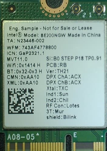
PD9BE200NG
Sep 13, 2023Intel BE200
Equipment Class
6CD - 15E 6 GHz Low Power Dual Client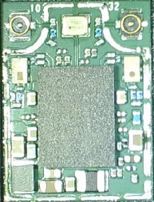
PD9BE200D2
Sep 13, 2023Intel BE200
Equipment Class
6CD - 15E 6 GHz Low Power Dual Client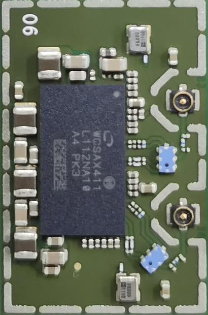
PD9AX411E2
Sep 30, 2021Intel Wi-Fi 6E AX411
Equipment Class
DTS - Digital Transmission System