PD918260NGWireless Network Adapter
Intel Corporation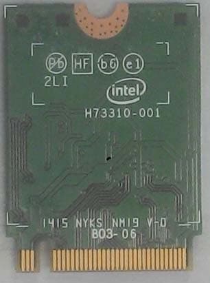
Click to zoom
Application Details
- Equipment Class
- DXT - Part 15 Low Power Transceiver, Rx Verified
- Date of Grant
- Oct 22, 2015
- Application Purpose
- Original Equipment
- Date of Application
- Oct 22, 2015
- Equipment Note
- Wireless Network Adapter
- Frequency Range
- 58320.00000000 - 62640.00000000
- Company
- Intel Corporation
- Country
- France
Documents & Files
Document Text
Text extracted from the exhibit documents filed with the FCC. Open a document above to read the original.
Users Manual
Document Number: 537178-3.3 Intel ® Wireless Gigabit v2.0 User Guide October 2015 Revision 3.3 Intel Confidential Intel ® Wireless Gigabit v2.0 User Guide October 2015 2 Intel Confidential Document Number: 537178-3.3 Notice: This document contains information on products in the design phase of development. The information here is subject to change without notice. Do not finalize a design with this information. INFORMATION IN THIS DOCUMENT IS PROVIDED IN CONNECTION WITH INTEL PRODUCTS. NO LICENSE, EXPRESS OR IMPLIED, BY ESTOPPEL OR OTHERWISE, TO ANY INTELLECTUAL PROPERTY RIGHTS IS GRANTED BY THIS DOCUMENT. EXCEPT AS PROVIDED IN INTEL’S TERMS AND CONDITIONS OF SALE FOR SUCH PRODUCTS, INTEL ASSUMES NO LIABILITY WHATSOEVER AND INTEL DISCLAIMS ANY EXPRESS OR IMPLIED WARRANTY, RELATING TO SALE AND/OR USE OF INTEL PRODUCTS INCLUDING LIABILITY OR WARRANTIES RELATING TO FITNESS FOR A PARTICULAR PURPOSE, MERCHANTABILITY, OR INFRINGEMENT OF ANY PATENT, COPYRIGHT OR OTHER INTELLECTUAL PROPERTY RIGHT. A "Mission Critical Application" is any application in which failure of the Intel Product could result, directly or indirectly, in personal injury or death. SHOULD YOU PURCHASE OR USE INTEL’S PRODUCTS FOR ANY SUCH MISSION CRITICAL APPLICATION, YOU SHALL INDEMNIFY AND HOLD INTEL AND ITS SUBSIDIARIES, SUBCONTRACTORS AND AFFILIATES, AND THE DIRECTORS, OFFICERS, AND EMPLOYEES OF EACH, HARMLESS AGAINST ALL CLAIMS COSTS, DAMAGES, AND EXPENSES AND REASONABLE ATTORNEYS' FEES ARISING OUT OF, DIRECTLY OR INDIRECTLY, ANY CLAIM OF PRODUCT LIABILITY, PERSONAL INJURY, OR DEATH ARISING IN ANY WAY OUT OF SUCH MISSION CRITICAL APPLICATION, WHETHER OR NOT INTEL OR ITS SUBCONTRACTOR WAS NEGLIGENT IN THE DESIGN, MANUFACTURE, OR WARNING OF THE INTEL PRODUCT OR ANY OF ITS PARTS. Intel may make changes to specifications and product descriptions at any time, without notice. Designers must not rely on the absence or characteristics of any features or instructions marked “reserved” or “undefined.” Intel reserves these for future definition and shall have no responsibility whatsoever for conflicts or incompatibilities arising from future changes to them. The information here is subject to change without notice. Do not finalize a design with this information. Intel software products are copyrighted by and shall remain the property of Intel Corporation. Use, duplication, or disclosure is subject to restrictions stated in Intel’s Software License Agreement, or in the case of software delivered to the government, in accordance with the software license agreement as defined in FAR 52.227-7013. The products described in this document may contain design defects or errors known as errata which may cause the product to deviate from published specifications. Current characterized errata are available on request. The code names presented in this document are only for use by Intel to identify products, technologies, or services in development that have not been made commercially available to the public, i.e., announced, launched, or shipped. They are not "commercial" names for products or services and are not intended to function as trademarks. Contact your local Intel sales office or your distributor to obtain the latest specifications and before placing your product order. Copies of documents which have an order number and are referenced in this document, or other Intel literature may be obtained by calling 1-800-548-4725 or by visiting Intel’s website at http://www.intel.com/design/literature.htm. Intel is a trademark of Intel Corporation or in the US and other countries. * Other brands and names may be claimed as the property of others. Copyright © 2015 Intel Corporation. All rights reserved. Intel ® Wireless Gigabit v2.0 October 2015 User Guide Document Number: 537178-3.3 Intel Confidential 3 Contents 1 Introduction ................................................................................................................. 8 1.1 Scope ............................................................................................................... 8 1.2 References......................................................................................................... 8 1.3 Wireless docking ................................................................................................. 8 1.3.1 “Place to Dock, Snap to Go” experience ................................................. 8 1.3.2 Wireless Docking (WiDock) and Wireless Display (WiDi) ........................... 8 1.3.3 Wireless peripheral ............................................................................. 9 1.4 Key features ...................................................................................................... 9 1.5 SW and HW deliverables ...................................................................................... 9 1.6 Notebook platform preparations for WiDock ............................................................ 9 1.7 Known limitations ............................................................................................... 9 2 Software Install .......................................................................................................... 10 2.1 NB-side installation ............................................................................................ 10 3 WiGig Application User Manual for Win 7/8/8.1 ......................................................... 12 3.1 User manual ..................................................................................................... 12 3.1.1 Launching the Intel ® Wireless Dock Manager ......................................... 12 3.1.2 Making the first connection ................................................................. 12 3.1.3 Automatic connection default .............................................................. 15 3.1.4 Automatic connections ....................................................................... 16 3.1.5 Manually connecting to a dock .…
Text truncated - open the document above for the full version.
Cover Letter(s)
100 Center Point Circle Columbia, SC 29210 October 15, 2015 Subject: Co nfidentiality Request for FCC ID: PD918260NG Pursu ant to FCC 47 CRF 0.457(d) and 0.459 the applicant requests that a part of the subject FCC application be held confidential. Type of Confidentiality Requested Short Term Permanent Short Term Short Term Permanent Short Term Permanent Short Term Permanent Short Term Permanent Short Term Permanent Short Term Permanent Short Term Short Term Permanent Short Term Exhibit Block Diagrams External Photos Internal Photos Operation Descriptio n/WiFi/BT Antenna Specification Operation Descriptio n/WiGig Antenna Specification Operation Descrip tion/HW Theory of Operation Operational Descrip tion/BT FHSS Description Schematics Test Setup Photos User’s Manual Intel Mobile Communications has spent substantial effort in developing this product and it is one of the first of its kind in industry. Having the subject information easily available to "competition" would negate the advantage they have achieved by developing this product. Not protecting the details of the design will result in financial hardship. Permanent Confidentiality: The applicant requests the exhibits listed above as permanently confidential be permanently withheld from public review due to materials that contain trade secrets and proprietary information not customarily released to the public. Short-Term Confidentiality: The applicant requests the exhibits selected above as short term confidential be withheld from public view for a period of 180 days from the date of the Grant of Equipment Authorization and prior to marketing. This is to avoid premature release of sensitive information prior to marketing or release of the product to the public. Applicant is also aware that they are responsible to notify ACB in the event information regarding the product or the product is made available to the public. ACB will then release the documents listed above for public disclosure pursuant to FCC Public Notice DA 04-1705. Sincerely, Steven C. Hackett By: __________________________ ________________________ (Signature/Title 1 ) (Print Name)
Cover Letter(s)
FCC ID: PD918260NG Software Security Description – KDB 594280 D02v01r02 Section II General Description 1. Describe how any software/firmware update will be obtained, downloaded, and installed. Software that is accessed through manufacturer’s website or device’s management system, must describe the different levels of security. There is no downloadable software provided by the manufacturer that can modify critical radio transmitter parameters. All critical parameters are programmed in OTP memory at the factory and cannot be modified or overridden by third parties. 2. Describe all the radio frequency parameters that are modified by any software/firmware without any hardware changes. Are these parameters in some way limited, such that, it will not exceed the authorized parameters? There are no rf parameters that can be modified. All rf parameters are programmed in OTP memory at the factory and cannot be modified or overridden by third parties. 3. Describe in detail the authentication protocols that are in place to ensure that the source of the software/firmware is legitimate. Describe in detail how the software is protected against modification. The firmware is programmed at the factory and cannot be modified by third parties. 4. Describe in detail the verification protocols in place to ensure that installed software/firmware is legitimate. The firmware is programmed at the factory and cannot be modified by third parties. 5. Describe in detail any encryption methods used to support the use of legitimate software/firmware. The firmware is programmed at the factory and cannot be modified by third parties therefore no encryption is necessary. 6. For a device that can be configured as a master and client (with active or passive scanning), explain how the device ensures compliance for each mode? In particular if the device acts as master in some band of operation and client in another; how is compliance ensured in each band of operation? T his is a client module only. Third‐Pa rty Access Control 1. Explain if any third parties have the capability to operate a US sold device on any other regulatory domain, frequencies, or in any manner that is in violation of the certification. Third parties do not the capability to operate in any manner that is violation of the certification in the U.S. 2. What prevents third parties from loading non‐US versions of the software/firmware on the device? Describe in detail how the device is protected from “flashing” and the installation of third‐party firmware such as DD‐WRT. (See, for example, http://www.dd‐ RF parameters are programmed into OTP memory at the factory and cannot be reprogrammed or re-flashed by third parties. FCC ID: PD918260NG wrt.com/) 3. For Certified Transmitter modular devices, describe how the module grantee ensures that hosts manufactures fully comply with these software security requirements for U‐NII devices. If the module is controlled through driver software loaded in the host, describe how the drivers are controlled and managed such that the modular transmitter pa rameters are not modified outside the grant of authorization. There are no rf parameters that can be modified. All rf parameters are programmed in OTP memory at the factory and cannot be modified or overridden by third parties. The module is not controlled by driver software on the host and cannot override critical rf parameters stored in module OTP memory. SOFTWARE CONFIGURATION DESCRIPTION – KDB 594280 D02v01r02 Section III USER CONFIGURATION GUIDE 1. To whom is the UI accessible? (Professional installer, end user, other.) No UI provided. a) What parameters are viewable to the professional installer/end‐user? None b) What parameters are accessible or modifiable to the professional installer? None i) Are the parameters in some way limited, so that the installers will not enter parameters that exceed those authorized? The module micro-code reads the parameters from the module OTP memory. These parameters cannot be modified or overridden by sw drivers. ii) What controls exist that the user cannot operate the device outside its authorization in the U.S.? Default mode is always FCC compliant. Other country modes cannot be activated without receiving three independent country codes from different APs, otherwise remains in FCC default mode (always FCC compliant) c) What configuration options are available to the end‐user? None i) Are the parameters in some way limited, so that the installers will not enter parameters that exceed those authorized? The module micro-code reads the parameters from the module OTP memory. These parameters cannot be modified or overridden by sw drivers. ii) What controls exist that the user cannot operate the device outside its authorization in the U.S.? Default mode is always FCC compliant. Other country modes cannot be activated without receiving three independent country codes from different APs, otherwise remains in FCC default mode (always FCC compliant) d) Is the country code factory set? Can it be changed in the UI? Default country code is set in the factory and no UI is provided for modification. i)If so, what controls exist to ensure that the device can only operate within its authorization in the Programmed for default mode which is always FCC compliant. Always set for default for all start-ups, resets, timeouts or other host or network events. FCC ID: PD918260NG U.S.? e) What are the default parameters when the device is restarted? Always FCC compliant 2.Can the radio be configured in bridge or mesh mode? If yes, an attestation may be required. Further information is available in KDB Publication 905462 D02. No 3.For a device that can be configured as a master and client (with active or passive scanning),if this is user configurable, describe what controls exist, within the UI, to ensure compliance for each mode. If the device acts as a master in some bands and client in others, how is thi s configured to ensure compliance? This is a client devi…
Text truncated - open the document above for the full version.
Cover Letter(s)
Intel Corporation 100 Center Point Circle Columbia, SC 29210 Modular Approval Requirements Attestation FCC ID: PD918260NG Modular Approval is being requested for this device under the ID’s listed above. This device is a self contained, physically delineated, component for which compliance was d emonstrated independent of any host operating conditions and complies with all eight requirements of FCC Part 15.212(a)(1). The details of these requirements and the manner in wh ich the devices meet them are summarized below. The module must have its own RF shielding. The module contains a metal shield which covers all RF components and circuitry; this shield is located on the top side of the board located next to the antenna connectors. All modulation and data input(s) are buffered. Data to the modulation circuit is buffered on the module; please refer to the “theory of operation” document filed with this application for full description. The module has its own power supply regulation and local reference oscillator. The module contains its own power supply regulation and the rf reference oscillator is contained within the module. Please refer to the schematics and “theory of operation” documents filed with this application for full description. The modular transmitter must comply with the antenna requirements of Section 15.203 and 15.204(c). The certification submission contains a detailed description of all antennas that will be used with the module. The module connects to its antenna via using an UFL type connector. This antenna connector is a non-standard connector. The antenna tested was a PIFA type and the data sheet is included in the application. The modular transmitter must be tested in a stand-alone configuration, i.e., the module must not be inside another device during testing. Test data contained in this application is for the device tested as a stand-alone device connected externally to a PC. See test set-up photographs filed with this application. For the FCC, the modular transmitter must be labeled with its own FCC ID number, and, if the FCC ID is not visible when the module is installed inside another device, then the outside of the device into which the module is installed must also display a label referring to the Intel Corporation 100 Center Point Circle Columbia, SC 29210 enclosed module. This exterior label can use wording such as the following: “Contains Transmitter Module FCC ID: XYZMODEL1” or “Contains FCC ID: XYZMODEL1.” For Industry Canada, the module meets certification labeling requirements for Category I Equipment. The module is appropriately labeled (refer to the label and label location drawings contained within this application). Information to the integrator of this device regarding the labeling requirements for the host system is contained in the instructions provided with the module. The modular transmitter must comply with any applicable RF exposure requirements. The module meets the requirements for a mobile/portable device that may be used at separation distances of more than 8mm from the human body. Refer to the RF Exposure test report submitted with this application.
ID Label/Location Info
Or Label & Location
Test Report
Intel Mobile Communications France S.A.S – WRF Lab 425 rue de Goa – Le Cargo B6 – 06600, Antibes, France Tel. +33493001400 / Fax +33493001401 TEST REPORT EUT Description WiGig, WLAN and BT, 2x2 PCIe M.2 adapter card Brand Name Intel® Tri-Band Wireless-AC 18260 Model Name 18260NGW, 18260NGW LC Serial Number WiGig MAC: 34:13:E8:06:2D:59 / 34:13:E8:05:F3:5D (see section 4) FCC/IC ID FCC ID: PD918260NG IC ID: 1000M-18260NG Antenna type Intel ® Wireless Gigabit Antenna-M 10041R (Array Antenna Model No . 10041RRFW) Hardware/Software Version HW config: 31.1 Test SW: DRTU version 1.8.3-01157 Driver ver.: 2.0.130.118 Date of Sample Receipt 2015-08-11 Date of Test Start/End 2015-08-11 / 2015-09-17 Features WiGig + 802.11 a/b/g/n/ac Wireless LAN + BDR/EDR 2.1 + BLE 4.0 (see section 5) Applicant Intel Mobile Communications Address 100 Center Point Circle, Suite 200 Columbia, South Carolina 29210 USA Contact Person Steven Hackett Telephone/Fax/ Email [email protected] Reference Standards FCC CFR Title 47 Part 15C, Part 2.1091 IC RSS-210 Issue 8, IC RSS-Gen Issue 4, IC RSS-102 (see section 1) Test Report number 15081803.TR04 Revision Control Rev. 02 The test results relate only to the samples tested. The test report shall not be reproduced in full, without written approval of the laboratory. Issued by Reviewed by Approved by Olivier FARGANT (RF Test Lead) Jose M. FORTES (Technical Manager) Nawfal ASRIH (Laboratory Manager) TESTING CERT #3478.01 Test Report N°15081803.TR04 Rev. 02 FO-014: Test Report 2 of 33 Printed copies are not controlled documents Table of Contents 1. Standards, reference documents and applicable test methods ............................................... 3 2. General conditions, competences and guarantees .................................................................... 3 3. Environmental Conditions............................................................................................................. 3 4. Test samples ................................................................................................................................... 4 5. EUT Features .................................................................................................................................. 4 6. Remarks and comments ................................................................................................................ 4 7. Test Verdicts summary .................................................................................................................. 5 8. Document Revision History .......................................................................................................... 5 Annex A. Test & System Description ............................................................................................. 6 A.1 EUT DESCRIPTION ........................................................................................................................................ 6 A.2 MEASUREMENT SYSTEM ................................................................................................................................ 7 A.3 TEST EQUIPMENT LIST ................................................................................................................................. 10 A.4 MEASUREMENT UNCERTAINTY EVALUATION.................................................................................................... 11 Annex B. Tests Results .................................................................................................................. 12 B.1 EMISSION BANDWIDTH ............................................................................................................................... 12 B.2 PEAK AND AVERAGE POWER, RF DETECTOR .................................................................................................... 16 B.3 CONDUCTED PEAK OUTPUT POWER, RF DETECTOR ........................................................................................... 18 B.4 SPURIOUS EMISSIONS ................................................................................................................................. 19 B.5 FREQUENCY STABILITY ................................................................................................................................. 26 B.6 GROUP INSTALLATION ................................................................................................................................. 28 B.7 RF EXPOSURE ............................................................................................................................................ 29 Annex C. Photographs ................................................................................................................... 31 C.1 RADIATED TEST SETUP ................................................................................................................................ 31 C.2 TEST SAMPLE ............................................................................................................................................ 32 Test Report N°15081803.TR04 Rev. 02 FO-014: Test Report 3 of 33 Printed copies are not controlled documents 1. Standards, reference documents and applicable test methods 1. FCC 47 CFR Part 15 - Subpart C – §15.255 Operation within the band 57-64 GHz. 2. ANSI C63.10-2013, Clause 9 – Procedures for testing millimeter-wave systems. 3. IC RSS-Gen Issue 4 – General Requirements for Compliance of Radio Apparatus. 4. IC RSS-210 Issue 8 – Licence-exempt Radio Apparatus (All Frequency Bands): Category I Equipment. 5. FCC 47 CFR Part 2 – Subpart J – §2.1091 Radiofrequency radiation exposure evaluation: mobile devices. 6. IC RSS-102 Issue 5 – Radio Frequency (RF) Exposure Compliance of Radiocommunication Apparatus (All Frequency Bands). 2. General conditions, competences and guarantees Intel Mobile Communications Wireless RF Lab (Intel WRF Lab) is a testing laboratory accredited by the American Association fo…
Text truncated - open the document above for the full version.
Test Setup Photos
Test Report N°15081803.TR04 Rev. 00 FO-014: Test Report 31 of 33 Printed copies are not controlled documents Annex C. Photographs C.1 Radiated Test Setup 30 MHz – 1 GHz 1 GHz – 18 GHz 18-40 GHz 40-200 GHz Test Report N°15081803.TR04 Rev. 00 FO-014: Test Report 32 of 33 Printed copies are not controlled documents C.2 Test Sample Sample #01 – Module Sample #02 – Module 3 Sample #01 – Extender board Sample #02 – Extender board WiGig Antenna Test Report N°15081803.TR04 Rev. 00 FO-014: Test Report 33 of 33 Printed copies are not controlled documents Laptop AC/DC adapter PCI cable PCIe Extender Express Card Adpapter
Contact Information
Applicant
Benjamin Lavenant(Regulatory Engineer)
Technical Contact
Intel Mobile CommunicationsSteven Hackett
[email protected]8032162344
100 Center Point Circle Suite 200 · Columbia, South Carolina · United States
Test Firm
Intel Mobile Commmunications France S.A.S.Nawfal Asrih
Technical Specifications
| # | Rule Parts | Frequency Range | Power Output |
|---|---|---|---|
| 1 | 15C | 58.32 GHz - 62.64 GHz | 12.00 mW |
Other Applications from Intel Corporation
PD9BE201D2P
Aug 20, 2024Intel BE201D2WP
Equipment Class
NII - Unlicensed National Information Infrastructure TXPD9AX411NG
Jul 02, 2024Intel WiFi 6E AX411
Equipment Class
6CD - 15E 6 GHz Low Power Dual ClientPD9AX211D2H
Jan 28, 2024Intel Wi-Fi 6E AX211
Equipment Class
DSS - Part 15 Spread Spectrum Transmitter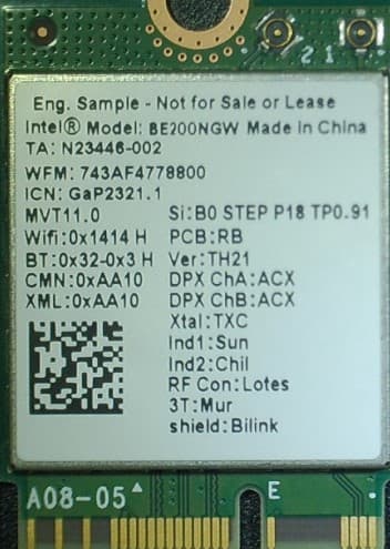
PD9BE200NG
Sep 13, 2023Intel BE200
Equipment Class
6CD - 15E 6 GHz Low Power Dual Client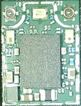
PD9BE200D2
Sep 13, 2023Intel BE200
Equipment Class
6CD - 15E 6 GHz Low Power Dual Client