PD94965AGNIntel Wireless WiFi Link 4965AGN
Intel Corporation
Click to zoom
Application Details
- Equipment Class
- DTS - Digital Transmission System
- Date of Grant
- Nov 16, 2006
- Application Purpose
- Original Equipment
- Date of Application
- Nov 01, 2006
- Equipment Note
- Intel Wireless WiFi Link 4965AGN
- Frequency Range
- 5745.00000000 - 5825.00000000
- Company
- Intel Corporation
- Country
- France
Documents & Files
Document Text
Text extracted from the exhibit documents filed with the FCC. Open a document above to read the original.
Users Manual
Intel(R) Wireless WiFi Link 4965AGN User Guide With your wireless network card, you can access wireless networks, share files or printers, or even share your Internet connection. All of these features can be explored with a wireless network in your home or office. This wireless local area network (WLAN) solution is designed for both home and business use. Additional users and features can be added as your networking needs grow and change. Your Intel(R) Wireless WiFi Link 4965AGN adapter is compatible with 802.11a, 802.11b 802.11g and 802.11n wireless standards. Operating at 5 GHz or 2.4 GHz frequency at speeds of up to 54 Mbps you can now connect your computer to existing high-speed networks that use multiple access points within large or small environments. Your wireless adapter maintains automatic data rate control according to access point location to achieve the fastest possible connection. All of your wireless network connections are easily managed by Intel(R) PROSet/Wireless software. Profiles that are set up through the Intel PROSet/Wireless software provide enhanced security measures with 802.1x network authentication. NOTE: The software is compatible with the Intel(R) Wireless WiFi Link 4965AGN, Intel(R) Wireless WiFi Link 4965AG_, Intel(R) PRO/Wireless 3965ABG Network Connection, Intel(R) PRO/Wireless 3945ABG Network Connection, Intel(R) PRO/Wireless 3945BG Network Connection, Intel(R) PRO/Wireless 2915ABG Network Connection and the Intel(R) PRO/Wireless 2200BG Network Connection. Table of Contents Use Intel PROSet/Wireless Software Connect to a Network Use Profiles Set up Security Troubleshooting Administrator Tool Glossary Wireless Network Overview Security Overview Specifications Customer Support Safety and Regulatory Information Warranty Adapter Registration Information in this document is subject to change without notice. © 2004–2006 Intel Corporation. All rights reserved. Intel Corporation, 5200 N.E. Elam Young Parkway, Hillsboro, OR 97124-6497 USA The copying or reproducing of any material in this document in any manner whatsoever without the written permission of Intel Corporation is strictly forbidden. Intel(R) is a trademark or registered trademark of Intel Corporation or its subsidiaries in the United States and other countries. Other trademarks and trade names may be used in this document to refer to either the entities claiming the marks and names or their products. Intel disclaims any proprietary interest in trademarks and trade names other than its own. Microsoft and Windows are registered trademarks of Microsoft Corporation. Windows Vista is either a registered trademark or trademark of Microsoft Corporation in the United States and/or other countries. *Other names and brands may be claimed as the property of others. Intel Corporation assumes no responsibility for errors or omissions in this document. Nor does Intel make any commitment to update the information contained herein. "Important Notice FOR ALL USERS OR DISTRIBUTORS!!!! Intel wireless LAN adapters are engineered, manufactured, tested, and quality checked to ensure that they meet all necessary local and governmental regulatory agency requirements for the regions that they are designated and/or marked to ship into. Since wireless LANs are generally unlicensed devices that share spectrum with radars, satellites, and other licensed and unlicensed devices, it is sometimes necessary to dynamically detect, avoid, and limit usage to avoid interference with these devices. In many instances Intel is required to provide test data to prove regional and local compliance to regional and governmental regulations before certification or approval to use the product is granted. Intel's wireless LAN's EEPROM, firmware, and software driver are designed to carefully control parameters that affect radio operation and to ensure electromagnetic compliance (EMC). These parameters include, without limitation, RF power, spectrum usage, channel scanning, and human exposure. For these reasons Intel cannot permit any manipulation by third parties of the software provided in binary format with the wireless LAN adapters (e.g., the EEPROM and firmware). Furthermore, if you use any patches, utilities, or code with the Intel wireless LAN adapters that have been manipulated by an unauthorized party (i.e., patches, utilities, or code (including open source code modifications) which have not been validated by Intel), (i) you will be solely responsible for ensuring the regulatory compliance of the products, (ii) Intel will bear no liability, under any theory of liability for any issues associated with the modified products, including without limitation, claims under the warranty and/or issues arising from regulatory non-compliance, and (iii) Intel will not provide or be required to assist in providing support to any third parties for such modified products. Note: Many regulatory agencies consider Wireless LAN adapters to be "modules", and accordingly, condition system-level regulatory approval upon receipt and review of test data documenting that the antennas and system configuration do not cause the EMC and radio operation to be non-compliant." October 2006 Back to Contents Use Intel(R) PROSet/Wireless Software Use Intel PROSet/Wireless as your Wireless Manager Start Intel PROSet/Wireless Start Intel PROSet/Wireless from the Taskbar l Taskbar Icons l Tool Tips and Desktop Alerts Intel PROSet/Wireless Main Window l Wireless Networks List l Connection Status Icons l Network Properties l Connection Details l Profiles List Intel PROSet/Wireless Menus l Tools Menu m Application Settings m Intel Wireless Troubleshooter m Administrator Tool l Advanced Menu m Adapter Settings m Advanced Statistics m Use Windows to Manage Wi-Fi l Profiles Menu m Manage Profiles m Manage Exclusions Turn Wireless Radio On or Off Install and Uninstall the Software Use Intel PROSet/Wireless as your Wireless Manager Intel(R) PROSet/Wireless is used to setup, edit and ma…
Text truncated - open the document above for the full version.
Cover Letter(s)
October 30, 2006 American TCB 6731 Whittier Ave., Suite C110 McLean, VA 22101 Gentlemen: The attached documentation is provided in support of a formal submission to your organization for a modular approval of an intentional unlicensed transmitter. On behalf of our client, Aegis Labs has included an application for a Grant of Equipment Authorization pursuant to Subpart C of part 15 of FCC Rules (47 CFR) regarding intentional radiators. The data within the test report demonstrates the equipment was tested in a manner described under Part 2 and 15 of the Code of Federal Regulations. This is a modular approval of the Intel PRO/Wireless 4965AGN Network Connection (MN: 4965AGN, FCC ID: PD94965AGN), which is a WLAN adapter (802.11a, 802.11b, 802.11g, and 802.11n). It was tested externally to a computer chassis with a set of Ethertronics Antennas continuously transmitting and receiving form Chain A, B, and C antenna ports. If there are any additional questions or if further information is needed, please contact us at your earliest convenience. Sincerely, Johnny Candelas Aegis Labs, Inc. Test Technician Enclosure (1 Emissions Test Report + Exhibits)
Cover Letter(s)
Intel® Wireless WiFi Link 4965AGN Product Description: The Intel® Wireless WiFi Link 4965AGN is an embedded 802.11a/b/g/Draft N ф PCIe * Mini Card network adapter card that operates in both the 2.4GHz and 5GHz spectra. This product delivers high throughput and a host of features that enhance today’s mobile lifestyle. Key Features : • Data rates up to 300 Mbps • Intel® Active Management Technology features deliver improved manageability over wireless LAN • IEEE 802.11e QoS with enhancements for VoIP • Wake on WLAN support • Interference Filter enhances performance in congested (noisy) wireless environments • Business Class Wireless Suite* (version 2) offers High Density Network and Enterprise Conferencing Enhancements • IEEE 802.11a/b/g/Draft N ф quad-mode Wireless LAN support (2.4GHz and 5GHz) • Highest industry-standard wireless LAN security support (802.11i, 802.1X, WEP*, WPA*, WPA2*, AES § ) • Cisco Compatible Extensions* v4 support available on certain models. Check with your PC manufacturer • Support for up to 3 antennas allows MIMO diversity for improved wireless throughput at longer range Intel® PROSet/Wireless Software v11.1 Intel ® PROSet/Wireless Software v11.1 is available for users of Intel ® Wireless and Intel ® PRO/Wireless hardware. The latest version of the software helps enable a superior experience via enhancements for end users as well as IT administrators who deploy and manage wireless networks. • Support for Microsoft Windows Vista* operating system • Support for high rate Draft N ф wireless networks • Support for Intel ® Active Management Technology • Support for Business Class Wireless Suite ◊ (v2): − High-Density Networking Enhancements − Enterprise Conferencing Enhancements • Support for Cisco Compatible Extensions* v4 • Support for Wi-Fi* Protected Setup for improved ease of use • Supports the following hardware: − Intel ® Wireless WiFi Link 4965AGN − Intel ® PRO/Wireless 3965ABG Network Connection − Intel ® PRO/Wireless 3945ABG Network Connection − Intel ® PRO/Wireless 2915ABG Network Connection − Intel ® PRO/Wireless 2200BG Network Connection (Note: Some features may only be supported on the latest hardware) Technical Specifications Product Name Intel® Wireless WiFi Link 4965AGN Dimensions (H x W x D) 2.00 in x 1.18 in x 0.13 in (50.95 mm x 30.00 mm x 3.30 mm) Weight 7g Antenna Interface Connector Hirose* U.FL-R-SMT mates with cable connector U.FL-LP-066 Antenna Diversity On-board diversity support for systems designed with two or three antennas Radio ON/OFF Control o Supported in both hardware and software Connector Interface Mini Card form factor, based on PCIe electrical interface LEDs output Link, Activity Operating Temperature 0 to +80° Celsius Humidity Non-Operating 50% to 90% RH non-condensing (at temperatures of 25°C to 35°C) Operating Systems Microsoft* Windows* Vista 32/64 bit, XP 32/64 bit, 2000, and Linux Wi-Fi Alliance Wi-Fi Certified* for 802.11a, 802.11b, 802.11g, WMM*, WPA*, and WPA2* Microsoft WHQL YES IEEE 802.11a, IEEE 802.11b, IEEE 802.11g, Draft N ф IEEE WLAN Standard Architecture Infrastructure or ad hoc (peer-to-peer) Roaming # Supports seamless roaming between respective access points (802.11b, 802.11g, 802.11a/b/g, and 802.11a/b/g/Draft N ф ) Security § Authentication WPA § and WPA2 § , 802.1X (EAP-TLS, TTLS, MD5, PEAP, LEAP, EAP-FAST), EAP-SIM Authentication Protocols PAP, CHAP, MD5, GTC, MS-CHAP*, MS-CHAPv2* Encryption 64-bit and 128-bit WEP, AES-CCMP, CKIP, TKIP Product Safety UL, C-UL, CB (IEC 60950) Products Available Model Code Intel® Wireless WiFi Link 4965AGN 4965AGN 4965AG_ (version with Draft N ф capabilities disabled) Ф “Draft N” refers to: IEEE P802.11n™/D1.0 Draft Amendment to STANDARD [FOR] Information Technology-Telecommunications and information exchange between systems-Local and Metropolitan networks-Specific requirements-Part 11: Wireless LAN Medium Access Control (MAC) and Physical Layer (PHY) specifications: Enhancements for Higher Throughput * Other names and brands may be claimed as the property of others. + W ireless connectivity and some features may require the purchase of additional software, services, or external hardware. Availability of public wireless LAN access points is limited, wireless functionality may vary by country and some hotspots may not support Linux-based Intel Centrino mobile technology systems. System performance measured by MobileMark* 2005. System performance, battery life, wireless performance, and functionality will vary depending on the specific operating system, hardware, and software configurations. See http://www.intel.com/products/centrino/more_info for more information. § Some security solutions, Intel ® PROSet/Wireless Software, and/or Business Class Wireless Suite features may not be supported by your PC’s operating system and/or by your PC manufacturer. Check with your PC manufacturer for details on availability. ◊ Intel ® PROSet/Wireless software may not be supported by your PC manufacturer. Check with your PC manufacturer for details on availability. # Roaming is supported only between each respective band and mode of access points. No license, express or implied, by estoppel or otherwise, to any intellectual property rights is granted by this document. Except as provided in Intel’s Terms and Conditions of Sale for such products, Intel assumes no liability whatsoever, and Intel disclaims any express or implied warranty, relating to sale and/or use of Intel products including without limitation, liability or warranties relating to fitness for a particular purpose, merchantability, or infringement of any patent, copyright or other intellectual property right. Intel products are not intended for use in medical, life saving, or life sustaining applications. Intel may make changes to specifications and product descriptions at any time, without notice. For the most current product information, please visit: http://www.intel.com/network. Intel, the Intel logo and the Intel Leap ahead…
Text truncated - open the document above for the full version.
External Photos
Top View Bottom View
ID Label/Location Info
D7390502 rev01 4965AGN/AG Generic M1 Pre-printed Artwork 1. ALL DIMENSIONS PER D5978901 CURRENT REV 2. ALL TEXT/GRAPHICS TO BE BLACK UNLESS OTHERWISE INDICATED 3. LABEL MATERIAL PER D5978901 CURRENT REV 2111 NE 25th Ave Hillsboro, OR 97124 1 3 2 D73905-002 Pb Regulatory approvals apply only to Intel authorized components, software and antenna solutions. Unauthorized installations or modifications will void regulatory approvals and product warranties. FCC ID: PD94965AGN IC: 1000M-4965AGN TA: XXXXXX-XXX Made in Xxxxxxxx MAC: OOOOOOMMMMMM Intel Wireless WiFi Link 4965AGN Model: 4965AGN MM1 CT: Label Location
Internal Photos
Top View “Insulation removed” Bottom View “Insulation removed” Top View “Shielding removed”
RF Exposure Info
MPE Calculations Systems operating under the provision of 47 CFR 1.1307(b)(1) shall be operated in a manor that ensures that the public is not exposed to radio frequency energy levels in excess of the FCC guidelines. The EUT will only be used with a separation of 20 centimeters or greater between the antenna and the body of the user or nearby persons and can therefore be considered a mobile transmitter per 47 CFR 2.1091(b). The MPE calculation for this exposure is shown below. Using the Antennas with highest output power: The peak radiated output power (EIRP) is calculated as follows: Antenna Frequency (GHz) Power input to the antenna (P) (dBm) Power gain of the antenna (G) (dBi) EIRP (P+G) (dBm) EIRP Log -1(dBm/10) (mW) Ethertronics (Chain A) 2.4 23.83 3.00 26.83 481.95 Ethertronics (Chain A) 5 20.91 5.00 25.91 389.94 Ethertronics (Chain B) 2.4 23.63 3.00 26.63 460.26 Ethertronics (Chain B) 5 20.61 5.00 25.61 363.92 EIRP = P + G Where P = Power input to the antenna (mW). G = Power gain of the antenna (dBi) The numeric gain (G) of the antenna with a gain specified in dB is determined by: Antenna Frequency (GHz) Antenna Gain (G) (dBi) Numeric Antenna Gain Log -1(dBm/10) (dB) Ethertronics (Chain A) 2.4 3.00 2.00 Ethertronics (Chain A) 5 5.00 3.16 Ethertronics (Chain B) 2.4 3.00 2.00 Ethertronics (Chain B) 5 5.00 3.16 G = Log -1 (dB antenna gain/10) Power density at the specific separation: Antenna Frequency (GHz) Power input to the antenna (P) (mW) Numeric Power Gain of the Antenna (G) (dB) Maximum Power Spectral Density S=PG/(4R 2 π) (mW/cm 2 ) Maximum Power Spectral Density Limit (mW/cm 2 ) Ethertronics (Chain A) 2.4 241.55 2.00 0.096 1.00 Ethertronics (Chain A) 5 123.31 3.16 0.078 1.00 Ethertronics (Chain B) 2.4 230.67 2.00 0.092 1.00 Ethertronics (Chain B) 5 115.08 3.16 0.072 1.00 S = PG/(4R 2 π) Where S = Maximum power density (mW/cm 2 ) P = Power input to the antenna (mW). G = Numeric power gain of the antenna R = Distance to the center of the radiation of the antenna (20cm = limit for MPE) The maximum permissible exposure (MPE) for the general population is 1mW/cm 2 . The power density at 20cm does not exceed the 1mW/cm 2 limit. Therefore, the exposure condition is compliant with FCC rules. Aggregate Maximum Power Spectral Density: Antenna Frequency (GHz) Maximum Power Spectral Density Chain A (dBi) Maximum Power Spectral Density Chain B (dBi) Maximum Power Spectral Density Aggregate Chain A & B (dBi) Maximum Power Spectral Density Limit (mW/cm 2 ) Ethertronics 2.4 0.096 0.092 0.094 1.00 Ethertronics 5 0.078 0.072 0.075 1.00
RF Exposure Info
The MPCI-8 model, part of the IMD Family of WLAN Internal Antennas, is a single element internal (embedded) antenna module for Worldwide WLAN applications. MPCI-8 supports 802.11a/b/g protocols throughout the world including the newly licensed 4.9 MHz Japanese spectrum. The MPCI-8 module is a complete solution consisting of one GS Isolated Magnetic Dipole™ (IMD) antenna with a high performance cable and connector. The IMD antenna’s small size and high isolation properties make the MPCI-8 easy to integrate into notebooks and other mobile devices, while offering the ability to be used in a diversity configuration. Ethertronics’ proprietary and patented IMD antenna technology offers three distinct advantages over traditional internal antennas: High Performance • High efficiency • Up to 50% higher signal strength than other internal antennas High Isolation/Selectivity • Minimal coupling between antennas (isolation of 20- 40 dB) • Ideal for diversity applications • Reduced EMI with surrounding components • Makes integration easy Shaping Technology • Controls and redirects the near-field electromagnetic distribution of the antenna’s wave • Optimizes antenna performance by improving signal strength and data quality inside buildings, in noisy environments and in fringe network coverage areas • Less interaction with surrounding objects The MPCI-8 module is ideally suited for manufacturers where performance, size and costs are critical. The design’s low profile, small form factor and industry standard cabling/connectors are suited for high volume applications. Standard assemblies are available or the antenna can be configured to suit individual OEM requirements. Advantages: WLAN 9605 Scranton Road, Suite 850 tel +(1) 858.550.3820 San Diego, CA 92121 • U.S.A. fax +(1) 858.550.3821 www.ethertronics.com [email protected] Ethertronics Applications: Notebooks • Tablet PCs Portable Computers • Printers Worldwide WLAN Coverage • Single internal antenna module covers worldwide WLAN frequency bands saving cost and valuable space • Supports WLAN bands for today’s standards allowing one configuration to support all markets Spatial Diversity • Individual MPCI-8 modules can be placed in close proximity to other IMD antennas with reduced risk of coupling from one to another Better Performance • Increased range/data throughput • Improved sensitivity in low signal environments Flexible Integration • MPCI-8 module’s high isolation offers consistent performance across multiple platforms and requires minimal space making placement easier • Standard cables and connectors make for easy connection to MPCI cards Worldwide Support • Regional technical support and FAEs are available to help speed the integration process • Manufacturing by Far East suppliers means quick turnaround and lower import costs WLAN Technologies: WiFi (802.11a/b/g) MPCI-8 (mini-PCI) Internal Antenna Module IMD WLAN Internal Antenna Module MPCI-8 2.4/4.9/5.2/5.8 GHz 37 x 4 x 5 mm (Antenna) 2.390-2.490/4.900-5.100 GHz/5.150-5.350/5.470-5.900 GHz Internal (Embedded) Antenna Specifications Typical Return Loss: Electrical Specifications: Antenna Radiation Patterns: 2.390-2.490 GHz Band 4.900-5.900 GHz Band Main-pol Cross-pol Mechanical Specifications: H-plane ( zx ) E-plane ( zy ) -30 dB -20 dB -10 dB 0 dB z y -30 dB -20 dB -10 dB 0 dB z y Typical Characteristics (Free Space) Size 40 x 52 x 6 mm (Antenna, 37 x 4 x 5 mm) Module Weight 5 g Packaging Individually packaged Cable/Connector Hirose Electric Co., U.FL-LP-088 or equivalent Cable Length 450 mm standard (50-500 mm available when specified) Model: MPCI-8 Module 2.390-2.490 GHz Band 4.900-5.100 GHz Band 5.150-5.350 GHz Band 5.470-5.900 GHz Band Peak Gain 3 dBi 3 dBi 5 dBi 5 dBi Efficiency 75 % 65 % 65 % 65 % VSWR Match 2.1 : 1 2.1 : 1 2.1 : 1 2.1 : 1 Front to Back Ratio -2 dB -10 dB -10 dB -10 dB Feed Point Impedance 50 ohms unbalanced (other if required) Power Handling 2 Watt cw Polarization Linear Shielding Ratio 6 to 1 (near field) Typical © 2003 Ethertronics. All rights reserved. Ethertronics, the Ethertronics logo, shaping antenna technology and Isolated Magnetic Dipole are trademarks of Ethertronics. All other trademarks are the property of their respective owners. 081803 22.533.544.555.566.57 -30 -25 -20 -15 -10 -5 0 Frequency, (GHz) dB -30 dB -20 dB -10 dB 0 dB x z Specifications subject to change without notice. -30 dB -20 dB -10 dB 0 dB z x
Test Report
FCC CFR47 PART 15 SUBPART E DFS TEST REPORT FOR 802.11 A/B/G/N MINI-PCI EXPRESS NETWORK ADAPTER MODEL NUMBER: 4965AGN FCC ID: PD94965AGN REPORT NUMBER: 06U10551-1 ISSUE DATE: OCTOBER 17, 2006 Prepared for INTEL 2111 N. E. 25TH AVE HILLSBORO, OR 97124 Prepared by COMPLIANCE CERTIFICATION SERVICES 561F MONTEREY ROAD MORGAN HILL, CA 95037, USA TEL: (408) 463-0885 FAX: (408) 463-0888 REPORT NO: 06U10551-1 DATE: OCTOBER 17, 2006 EUT: 802.11 a/b/g/n Mini-PCI Express Network Adapter FCC ID: PD94965AGN Page 2 of 25 COMPLIANCE CERTIFICATION SERVICES DOCUMENT NO: CCSUP4031A 561F MONTEREY ROAD, MORGAN HILL, CA 95037 USA TEL: (408) 463-0885 FAX: (408) 463-0888 This report shall not be reproduced except in full, without the written approval of CCS. Revision History Rev. Issue Date Revisions Revised By -- 10/17/06 Initial Issue AI REPORT NO: 06U10551-1 DATE: OCTOBER 17, 2006 EUT: 802.11 a/b/g/n Mini-PCI Express Network Adapter FCC ID: PD94965AGN Page 3 of 25 COMPLIANCE CERTIFICATION SERVICES DOCUMENT NO: CCSUP4031A 561F MONTEREY ROAD, MORGAN HILL, CA 95037 USA TEL: (408) 463-0885 FAX: (408) 463-0888 This report shall not be reproduced except in full, without the written approval of CCS. TABLE OF CONTENTS 1. ATTESTATION OF TEST RESULTS............................................................................................. 4 2. TEST METHODOLOGY .................................................................................................................. 5 3. FACILITIES AND ACCREDITATION .......................................................................................... 5 4. CALIBRATION AND UNCERTAINTY.......................................................................................... 5 4.1. MEASURING INSTRUMENT CALIBRATION ............................................................................. 5 5. EQUIPMENT UNDER TEST............................................................................................................6 5.1. DESCRIPTION OF EUT ..............................................................................................................6 5.2. SOFTWARE AND FIRMWARE .................................................................................................... 6 6. TEST AND MEASUREMENT EQUIPMENT ................................................................................ 7 7. LIMITS AND RESULTS ................................................................................................................... 8 7.1. DYNAMIC FREQUENCY SELECTION ....................................................................................... 8 7.1.1. LIMITS ................................................................................................................................. 8 7.1.2. DESCRIPTION OF EUT.................................................................................................... 11 7.1.3. TEST AND MEASUREMENT SYSTEM ......................................................................... 12 7.1.4. SETUP OF EUT AND SUPPORT EQUIPMENT ............................................................. 16 7.1.5. PLOTS OF NOISE, RADAR WAVEFORMS, AND WLAN SIGNALS.......................... 18 7.1.6. TEST CHANNEL AND METHOD ................................................................................... 21 7.1.7. CHANNEL MOVE TIME AND CHANNEL CLOSING TRANSMISSION TIME ......... 21 8. SETUP PHOTOS .............................................................................................................................. 24 REPORT NO: 06U10551-1 DATE: OCTOBER 17, 2006 EUT: 802.11 a/b/g/n Mini-PCI Express Network Adapter FCC ID: PD94965AGN Page 4 of 25 COMPLIANCE CERTIFICATION SERVICES DOCUMENT NO: CCSUP4031A 561F MONTEREY ROAD, MORGAN HILL, CA 95037 USA TEL: (408) 463-0885 FAX: (408) 463-0888 This report shall not be reproduced except in full, without the written approval of CCS. 1. ATTESTATION OF TEST RESULTS COMPANY NAME: Intel 2111 N. E. 25th Ave Hillsboro, OR 97124 EUT DESCRIPTION: 802.11 a/b/g/n Mini-PCI Express Network Adapter MODEL TESTED: 4965agn SERIAL NUMBER: KDR200060806D-2-R4 DATE TESTED: October 16, 2006 APPLICABLE STANDARDS STANDARD TEST RESULTS FCC PART 15 SUBPART E NO NON-COMPLIANCE NOTED Compliance Certification Services, Inc. tested the above equipment in accordance with the requirements set forth in the above standards. The test results show that the equipment tested is capable of demonstrating compliance with the requirements as documented in this report. Note: The results documented in this report apply only to the tested sample, under the conditions and modes of operation as described herein. This document may not be altered or revised in any way unless done so by Compliance Certification Services and all revisions are duly noted in the revisions section. Any alteration of this document not carried out by Compliance Certification Services will constitute fraud and shall nullify the document. No part of this report may be used to claim product certification, approval, or endorsement by NVLAP, NIST, or any government agency. Approved & Released For CCS By: Tested By: ALVIN ILARINA WILLIAM ZHUANG ENGINEERING MANAGER EMC ENGINEER COMPLIANCE CERTIFICATION SERVICES COMPLIANCE CERTIFICATION SERVICES REPORT NO: 06U10551-1 DATE: OCTOBER 17, 2006 EUT: 802.11 a/b/g/n Mini-PCI Express Network Adapter FCC ID: PD94965AGN Page 5 of 25 COMPLIANCE CERTIFICATION SERVICES DOCUMENT NO: CCSUP4031A 561F MONTEREY ROAD, MORGAN HILL, CA 95037 USA TEL: (408) 463-0885 FAX: (408) 463-0888 This report shall not be reproduced except in full, without the written approval of CCS. 2. TEST METHODOLOGY The tests documented in this report were performed in accordance with ANSI C63.4-2003, FCC CFR 47 Part 2, FCC CFR 47 Part 15 and FCC 06-96 APPENDIX “COMPLIANCE MEASUREMENT PROCEDURES FOR UNLICENSED-NATIONAL INFORMATION INFRASTRUCTURE DEVCIES OPERATING IN THE 5250-5350 MHz AND 5470-5725 MHz BANDS INCORPORATING DYNAMIC FREQUENCY SELECTION”. 3. FACILITIES …
Text truncated - open the document above for the full version.
Test Report
Page 1 of 22 Report Number: INTEL-060907F Revision Number: A1 Modular Approval Test Report And Application for Grant of Equipment Authorization TEST REPORT PERTAINING TO: Equipment Under Test Model Number(s) Intel PRO/Wireless 4965AGN Network Connection 4965AGN CONFIGURATION 802.11a / 802.11b / 802.11g / 802.11n with a set of Ethertronics Antennas MEASUREMENTS PERFORMED IN ACCORDANCE WITH THE FOLLOWING STANDARD (S) Regulatory Standard(s) 47 CFR Part 15, Subpart C Section 15.247 Test Method: ANSI C63.4: 2003 American National Standard for Methods of Measurement of Radio-Noise Emissions from Low- Voltage Electrical and Electronic Equipment in the Range of 9 kHz to 40 GHz PREPARED FOR: PREPARED BY: Intel Corporation Aegis Labs, Inc. 2111 NE 25 th Avenue 22431 Antonio Parkway B160-417 Hillsboro, Oregon 97124 Rancho S. Margarita, CA 92688 Contact(s): Mr. Robert Paxman Agent(s): Mr. Rick Candelas Mr. Johnny Candelas Test Report #: INTEL-060907F Test Report Revision: A1 APPENDICES REPORT BODY A B TOTAL PAGES PAGES 22 220 1 243 The contents of this report shall not be reproduced except in full, without the written approval of Aegis Labs, Inc. The Intel logo is used for identification purposes only and is a registered trademark of Intel Corporation Certificate Number: 1111.01 Page 2 of 22 Report Number: INTEL-060907F Revision Number: A1 TABLE OF CONTENTS SECTION TITLE PAGE COVER SHEET......................................................................................................... 01 TABLE OF CONTENTS.................................................................................................................... 02 1.0 REGULATORY COMPLIANCE GUIDELINES................................................................ 03 1.1 Guidelines For Testing To Emissions Standards..................................................................... 03 2.0 SUMMARY OF REGULATORY LIMITS.................................................................................. 04 3.0 ADMINISTRATIVE DATA AND TEST DESCRIPTION..................................................... 16 4.0 DESCRIPTION OF EUT CONFIGURATION....................................................................... 17 4.1 EUT Description ......................................................................................................... 17 4.2 EUT Configuration......................................................................................................................... 18 4.3 List of EUT Sub-Assemblies and Host Equipment........................................................................... 18 4.4 I/O Cabling Diagram and Description ................................................................................. 19 4.5 EMC Test Hardware and Software Measurement Equipment.............................................................. 20 5.0 CONDITIONS DURING EMISSIONS MEASUREMENTS................................................... 21 5.1 General..................................................................................................................... 21 5.2 Conducted Emissions Test Setup....…
Text truncated - open the document above for the full version.
Contact Information
Applicant
Benjamin Lavenant(Regulatory Engineer)
Technical Contact
Aegis Labs, Inc.Johnny Candelas
[email protected]949-459-7886
23091 Antonio Parkway #B160-417 · Rancho Santa Margarita, California · United States
Test Firm
AEGIS Labs, Inc.Steve Kuiper
Technical Specifications
| # | Rule Parts | Frequency Range | Power Output |
|---|---|---|---|
| 2 | 15C | 5.75 GHz - 5.83 GHz | 123.00 mW |
Other Applications from Intel Corporation
PD9BE201D2P
Aug 20, 2024Intel BE201D2WP
Equipment Class
NII - Unlicensed National Information Infrastructure TXPD9AX411NG
Jul 02, 2024Intel WiFi 6E AX411
Equipment Class
6CD - 15E 6 GHz Low Power Dual ClientPD9AX211D2H
Jan 28, 2024Intel Wi-Fi 6E AX211
Equipment Class
DSS - Part 15 Spread Spectrum Transmitter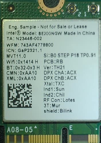
PD9BE200NG
Sep 13, 2023Intel BE200
Equipment Class
6CD - 15E 6 GHz Low Power Dual Client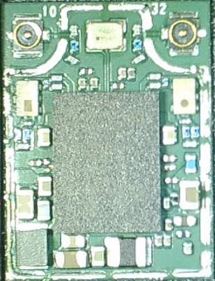
PD9BE200D2
Sep 13, 2023Intel BE200
Equipment Class
6CD - 15E 6 GHz Low Power Dual Client