PD9612BNXHUIntel Centrino Wireless-N+WiMax 6150
Intel Corporation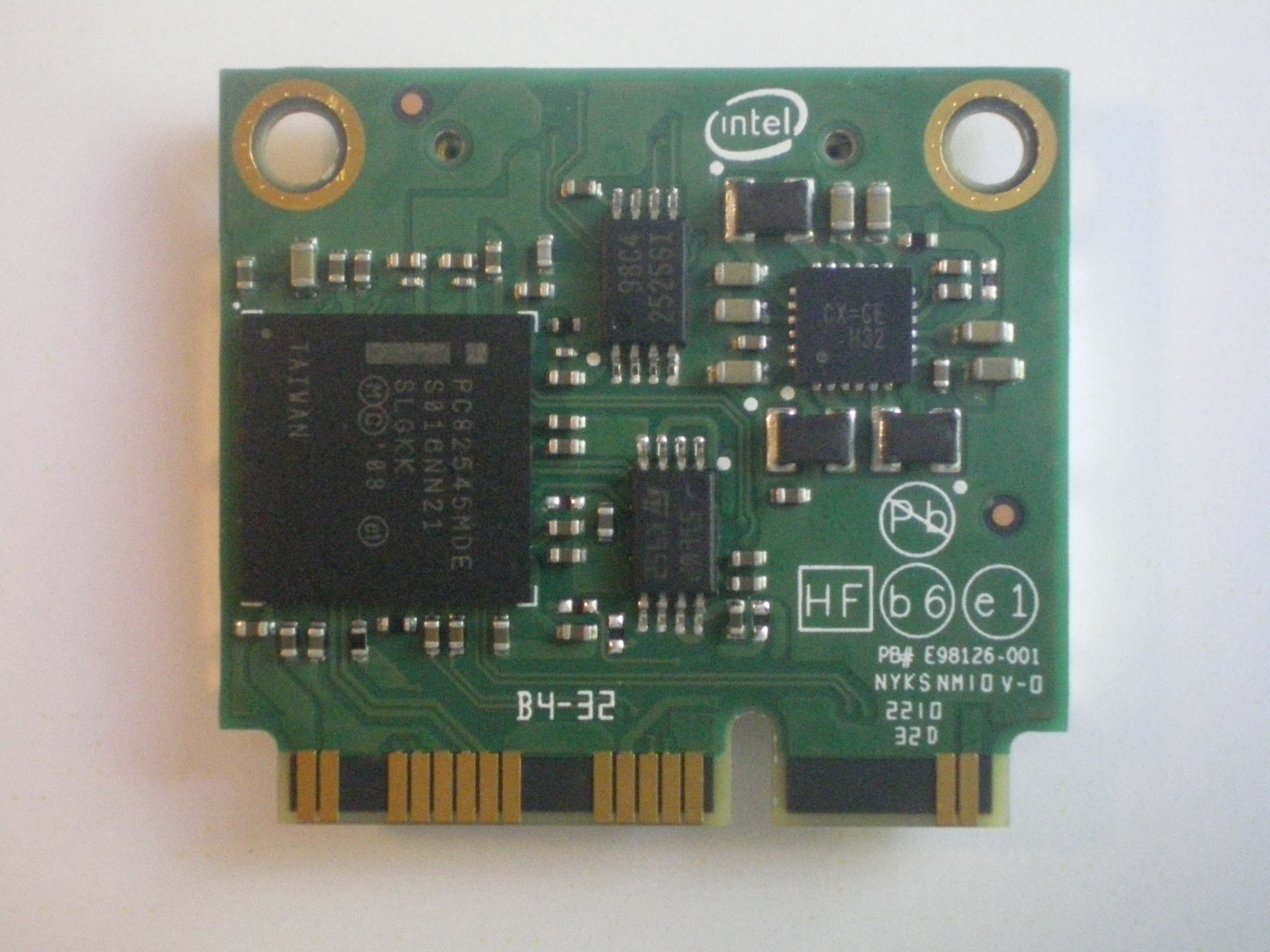
Click to zoom
Application Details
- Equipment Class
- TNB - Licensed Non-Broadcast Station Transmitter
- Date of Grant
- Sep 26, 2010
- Application Purpose
- Original Equipment
- Date of Application
- Sep 26, 2010
- Equipment Note
- Intel Centrino Wireless-N+WiMax 6150
- Frequency Range
- 2501.00000000 - 2685.00000000
- Company
- Intel Corporation
- Country
- France
Documents & Files
Document Text
Text extracted from the exhibit documents filed with the FCC. Open a document above to read the original.
Users Manual
Intel® Wireless Adapter Information Guide Supported wireless adapters: Intel® Centrino® Ultimate-N 6350 Intel® Centrino® Ultimate-N 6300 Intel® Centrino® Advanced-N + WiMAX 6250 Intel® Centrino® Advanced-N 6230 Intel® Centrino® Advanced-N 6205 Intel® Centrino® Advanced-N 6200 Intel® Centrino® Wireless-N + WiMAX 6150 Intel® WiFi Link 5300 Intel® WiMAX/WiFi Link 5150 Intel® WiFi Link 5100 Intel® Wireless WiFi Link 4965AGN Intel® PRO/Wireless 3945ABG Network Connection Intel® Centrino® Wireless-N 1030 Intel® Centrino® Wireless-N 100 Intel® Centrino® Wireless-N 130 With your WiFi network card, you can access WiFi networks, share files or printers, or even share your Internet connection. All of these features can be explored using a WiFi network in your home or office. This WiFi network solution is designed for both home and business use. Additional users and features can be added as your networking needs grow and change. This guide contains basic information about Intel adapters. It includes information about several adapter properties that you can set to control and enhance the performance of your adapter with your particular wireless network and environment. Intel® wireless adapters enable fast connectivity without wires for desktop and notebook PCs. Adapter Settings Regulatory Information Specifications Warranty Information Support Information Important Information Glossary Information in this document is subject to change without notice. © 2004–2010 Intel Corporation. All rights reserved. Intel Corporation, 5200 N.E. Elam Young Parkway, Hillsboro, OR 97124-6497 USA The copying or reproducing of any material in this document in any manner whatsoever without the written permission of Intel Corporation is strictly forbidden. Intel® is a trademark or registered trademark of Intel Corporation or its subsidiaries in the United States and other countries. Other trademarks and trade names may be used in this document to refer to either the entities claiming the marks and names or their products. Intel disclaims any proprietary interest in trademarks and trade names other than its own. Microsoft and Windows are registered trademarks of Microsoft Corporation. Windows Vista is either a registered trademark or trademark of Microsoft Corporation in the United States and/or other countries. *Other names and brands may be claimed as the property of others. Intel Corporation assumes no responsibility for errors or omissions in this document. Nor does Intel make any commitment to update the information contained herein. "IMPORTANT NOTICE FOR ALL USERS OR DISTRIBUTORS: Intel wireless LAN adapters are engineered, manufactured, tested, and quality checked to ensure that they meet all necessary local and governmental regulatory agency requirements for the regions that they are designated and/or marked to ship into. Because wireless LANs are generally unlicensed devices that share spectrum with radars, satellites, and other licensed and unlicensed devices, it is sometimes necessary to dynamically detect, avoid, and limit usage to avoid interference with these devices. In many instances Intel is required to provide test data to prove regional and local compliance to regional and governmental regulations before certification or approval to use the product is granted. Intel's wireless LAN's EEPROM, firmware, and software driver are designed to carefully control parameters that affect radio operation and to ensure electromagnetic compliance (EMC). These parameters include, without limitation, RF power, spectrum usage, channel scanning, and human exposure. For these reasons Intel cannot permit any manipulation by third parties of the software provided in binary format with the wireless LAN adapters (e.g., the EEPROM and firmware). Furthermore, if you use any patches, utilities, or code with the Intel wireless LAN adapters that have been manipulated by an unauthorized party (i.e., patches, utilities, or code (including open source code modifications) which have not been validated by Intel), (i) you will be solely responsible for ensuring the regulatory compliance of the products, (ii) Intel will bear no liability, under any theory of liability for any issues associated with the modified products, including without limitation, claims under the warranty and/or issues arising from regulatory non-compliance, and (iii) Intel will not provide or be required to assist in providing support to any third parties for such modified products. Note: Many regulatory agencies consider Wireless LAN adapters to be "modules", and accordingly, condition system-level regulatory approval upon receipt and review of test data documenting that the antennas and system configuration do not cause the EMC and radio operation to be non-compliant." August 11, 2010 Adapter Settings The Advanced tab displays the device properties for the WiFi adapter installed on your computer. This version of Intel® PROSet/Wireless WiFi Software is compatible with the following adapters: Intel® Centrino® Ultimate-N 6350 Intel® Centrino® Ultimate-N 6300 Intel® Centrino® Advanced-N + WiMAX 6250 Intel® Centrino® Advanced-N 6230 Intel® Centrino® Advanced-N 6205 Intel® Centrino® Advanced-N 6200 Intel® Centrino® Wireless-N + WiMAX 6150 Intel® WiFi Link 5300 Intel® WiMAX/WiFi Link 5150 Intel® WiFi Link 5100 Intel® Wireless WiFi Link 4965AGN Intel® PRO/Wireless 3945ABG Network Connection Intel® Centrino® Wireless-N 1030 Intel® Centrino® Wireless-N 100 Intel® Centrino® Wireless-N 130 How to Access For Windows* XP and Windows* 7 users: At the Intel® PROSet/Wireless WiFi Connection Utility, Advanced Menu click Adapter Settings. Select the Advanced tab. Open the Device Manager and click on the WiFi network adapter. Then select the Advanced tab. WiFi Adapter Settings Description Name Description 802.11n Channel Width (2.4 GHz) Set high throughput channel width to maximize performance. Set the channel width to Auto or 20MHz. Use 20MHz if 802.11n channels are restricted. This s…
Text truncated - open the document above for the full version.
Cover Letter(s)
American TCB 6731 Whittier Avenue, Suite C110 McLean, VA. 22101 September 21, 2010 To whom it may concern: The enclosed documents constitute a formal submittal and application for Equipment Authorization for modular approval for a composite device pursuant to the following rules: Subpart B of Part 15 of FCC Rules (CFR 47) – JBP Subpart C of Part 15 of FCC Rules (CFR 47) – 15.247 (DTS) Part 27 of FCC Rules (CFR 47) – TNB The device is a module meeting all of the requirements for modular approval. Two versions of the product are being submitted under two different IDs. This application, under FCC ID PD9612BNXHU, is for a limited single modular approval allowing installation by the end user into devices that have a BiOS lock to ensure that the module is only used in approved systems. Descriptions of the BiOS lock associated with this approval for two different integrators have uploaded as part of the operational description and are to be held confidential. Permanent or temporary confidentiality has been requested for additional documents – refer to the confidentiality request letter for details. Elliott Laboratories, as duly authorized agent prepared this submittal. A copy of the letter of our appointment as agent is included with the application. If there are any questions or if further information is needed, please contact Elliott Laboratories for assistance. Sincerely, Mark Briggs Staff Engineer MB/dmg
Cover Letter(s)
100 Center Point Circle Columbia, SC 29210 September 15, 2010 Subject: Confidentiality Request for FCC ID: PD9612BNXHU Pursuant to FCC 47 CRF 0.457(d) and 0.459 and IC RSP-100, Section 10, the applicant requests that a part of the subject FCC application be held confidential. Type of Confidentiality Requested Exhibit Short Term Permanent Block Diagrams Short Term External Photos Short Term Permanent* 1 Internal Photos Short Term Permanent Operation Description/Theory of Operation Short Term Permanent Operational Description/BiOS Lock Description Short Term Permanent Schematics Short Term Permanent Parts List - Part 27 Only Short Term Permanent Tune-Up Procedure - Part 27 Only Short Term Test Setup Photos Short Term Permanent* User’s Manual Intel Corporation has spent substantial effort in developing this product and it is one of the first of its kind in industry. Having the subject information easily available to "competition" would negate the advantage they have achieved by developing this product. Not protecting the details of the design will result in financial hardship. Permanent Confidentiality: The applicant requests the exhibits listed above as permanently confidential be permanently withheld from public review due to materials that contain trade secrets and proprietary information not customarily released to the public. Short-Term Confidentiality: The applicant requests the exhibits selected above as short term confidential be withheld from public view for a period of 180 days from the date of the Grant of Equipment Authorization and prior to marketing. This is to avoid premature release of sensitive information prior to marketing or release of the product to the public. Applicant is also aware that they are responsible to notify ATCB in the event information regarding the product or the product is made available to the public. ATCB will then release the documents listed above for public disclosure pursuant to FCC Public Notice DA 04- 1705. Sincerely, Steven C. Hackett By: __________________________ ________________________ (Signature/Title 2 ) (Print Name) 1 - The asterisked items (*) require further justification before permanent confidentiality will be allowed. These also currently require review by the FCC under their Permit-But-Ask policy before the grant is issued and can delay completion of an application. Further justification should be added to the note above. One such example for a potted device would be: “The EUT is FULLY potted using a non-removable epoxy based material. Removal of potting material causes irreparable damage to internal circuitry. See photographs exhibits that outline the device before and after potting.” 2 - Must be signed by applicant contact given for applicant on the FCC site, or by the authorized agent if an appropriate authorized agent letter has been provided. Letters should be placed on appropriate letterhead.
Cover Letter(s)
Intel Corporation 100 Center Point Circle Columbia, SC 29210 Modular Approval Requirements Attestation FCC ID: PD96212BNXHU Limited Modular Approval is being requested for this device under the ID’s listed above. Modules authorized under these ID’s are intended for installation into the host systems by the end users. In order to ensure compliance with all modular requirements, including RF exposure, the host system will be provided with a feature in BiOS that will allow operation of authorized modules only. The BiOS feature will lock-out any unauthorized devices from operation with the host system. The following paragraphs detail the modular requirements and the manner in which the devices meet them. The module meets all of the technical specifications applicable to the frequency band of operation. The module has its own RF shielding. The module contains a shield which covers the critical RF components; this shield is located on the top side of the board located next to the antenna connectors. All modulation and data input(s) are buffered. Data to the modulation circuit is buffered on the module; please refer to the “theory of operation” document for full details. The module has its own power supply regulation and local reference oscillator. The module contains its own power supply regulation and the rf reference oscillator is contained within the module. Please refer to the schematics and “theory of operation” documents for more detail. The modular transmitter must comply with the antenna requirements of Section 15.203 and 15.204(c). The certification submission contains a detailed description of all antennas that will be used with the module. The module connects to its antenna via using an UFL type connector. This antenna connector is a non-standard connector. The antenna tested was a PIFA type and the data sheet is included in the application. Intel Corporation 100 Center Point Circle Columbia, SC 29210 For Industry Canada, the module meets certification labeling requirements. Host devices that contain separately certified modules do not need to be re-certified, provided that they meet the following conditions: The host device, as a stand alone unit without any separately certified modules, complies with all applicable Radio Standard Specifications. The host device and all the separately certified modules it contains jointly meet the safety requirements of RSS-102, if applicable. The host device complies with the certification labeling requirements of each of the modules it contains. The module is appropriately labeled refer to the label and label location drawings contained within this application. For the FCC, the modular transmitter must be tested in a stand-alone configuration, i.e., the module must not be inside another device during testing. This is intended to demonstrate that the module is capable of complying with Part 15 emission limits regardless of the device into which it is eventually installed. Unless the transmitter module will be battery powered, it must comply with the AC line conducted requirements found in Section 15.207. Test data contained in this application is for the device tested as a stand-alone device. Radiated spurious emissions data and AC conducted emissions data demonstrating compliance with the requirements of Part 15 of the FCC rules for intentional radiators has been provided. For the FCC, the modular transmitter must be labeled with its own FCC ID number, and, if the FCC ID is not visible when the module is installed inside another device, then the outside of the device into which the module is installed must also display a label referring to the enclosed module. This exterior label can use wording such as the following: “Contains Transmitter Module FCC ID: XYZMODEL1” or “Contains FCC ID: XYZMODEL1.” The module is appropriately labeled (refer to the label and label location drawings contained within this application). Information to the integrator of this device regarding the labeling requirements for the host system is contained in the instructions provided with the module. The modular transmitter must comply with any applicable RF exposure requirements. The module meets the requirements for a mobile device that may be used at separation distances of more than 20cm from the human body. Refer to the MPE calculation data sheet. If the module is classified as a portable device due to antenna separation distance of less than 20cm from users then compliance for RF exposure rules will be demonstrated for those particular product configurations according to permissive change policies.
ID Label/Location Info
Photo showing label placement on half-mini card. Label wraps around onto the other side of the board. The side of the label with the FCC ID appears on the back of the board.
RF Exposure Info
MPE Calculations The device is not a portable device (i.e. intended to be worn on the body or be hand- held), so it is classified as being either a mobile device or a fixed mounted device. The user’s manual specifies a minimum separation distance of at least 20cm, consistent with this classification. FCC part 1.1310, Table 1 limits the power density for uncontrolled exposure. The power density, P d (mW/cm 2 ) calculated from the maximum EIRP, P t (mW) and the distance, d (m), between the transmitting antenna and the closest person, can be calculated using: P d = P t /(4 πd 2 ) Frequency MPE Limit (mW/cm 2 ) Output Power (mW) Max. Antenna Gain (dBi) EIRP (mW) Pd at 20cm (mW/cm 2 ) Distance where Pd = limit (cm) 2412 to 2462 MHz 1.00 60.3 3.2 125.9 0.03 3.2 2499 to 2688 MHz 1.00 263.0 3.5 584.8 0.1 6.8 As shown in the calculations above, the power density 20cm from the device is below the maximum permitted level for uncontrolled exposure.
Test Report
File: R80566 Page 1 of 16 Radio Test Report FCC Part 27 (2495 – 2690 MHz) Model: Intel Centrino Wireless-N + WiMAX 6150, Model: 612BNXHMW FCC ID: PD9612BNXH and PD9612BNXHU COMPANY: Intel Corporation 100 Center Point Circle Suite 200 Columbia, SC 29210 TEST SITE(S): Elliott Laboratories 41039 Boyce Road. Fremont, CA. 94538-2435 REPORT DATE: September 21, 2010 FINAL TEST DATES: August 17, 19, 20 and 23, 2010 AUTHORIZED SIGNATORY: ______________________________ Mark Briggs Staff Engineer Elliott Laboratories Elliott Laboratories is accredited by the A2LA, certificate number 2016-01, to perform the test(s) listed in this report, except where noted otherwise. This report shall not be reproduced, except in its entirety, without the written approval of Elliott Laboratories Elliott Laboratories -- EMC Department Test Report Report Date: September 21, 2010 File: R80566 Page 2 of 16 REVISION HISTORY Rev# Date Comments Modified By - 09-21-2010 First release Elliott Laboratories -- EMC Department Test Report Report Date: September 21, 2010 File: R80566 Page 3 of 16 TABLE OF CONTENTS REVISION HISTORY .............................................................................................................................................. 2 TABLE OF CONTENTS .......................................................................................................................................... 3 SCOPE........................................................................................................................................................................ 4 OBJECTIVE .............................................................................................................................................................. 5 STATEMENT OF COMPLIANCE......................................................................................................................... 5 DEVIATIONS FROM THE STANDARDS ............................................................................................................ 5 TEST RESULTS........................................................................................................................................................ 6 FCC PART 27 (2496 – 2690 MHZ MOBILE DIGITAL STATIONS)........................................................................ 6 EXTREME CONDITIONS .................................................................................................................................... 7 MEASUREMENT UNCERTAINTIES..................................................................................................................7 EQUIPMENT UNDER TEST (EUT) DETAILS .................................................................................................... 8 GENERAL.............................................................................................................................................................. 8 ENCLOSURE......................................................................................................................................................... 8 MODIFICATIONS................................................................................................................................................. 8 SUPPORT EQUIPMENT....................................................................................................................................... 8 EUT INTERFACE PORTS .................................................................................................................................... 9 EUT OPERATION ................................................................................................................................................. 9 TESTING ................................................................................................................................................................. 10 GENERAL INFORMATION ............................................................................................................................... 10 RF PORT MEASUREMENT PROCEDURES .................................................................................................... 10 OUTPUT POWER................................................................................................................................................ 11 BANDWIDTH MEASUREMENTS ....................................................................................................................11 CONDUCTED SPURIOUS EMISSIONS............................................................................................................ 11 TRANSMITTER MASK MEASUREMENTS..................................................................................................... 12 FREQUENCY STABILITY ................................................................................................................................. 12 RADIATED EMISSIONS MEASUREMENTS.................................................................................................... 12 INSTRUMENTATION ........................................................................................................................................ 14 FILTERS/ATTENUATORS ................................................................................................................................ 14 ANTENNAS......................................................................................................................................................... 14 ANTENNA MAST AND EQUIPMENT TURNTABLE ..................................................................................... 14 SAMPLE CALCULATIONS ................................................................................................................................. 15 SAMPLE CALCULATIONS - CONDUCTED SPURIOUS EMISSIONS ......................................................... 15 SAMPLE CALCULATIONS –RADIATED FIELD STRENGTH .............................…
Text truncated - open the document above for the full version.
Contact Information
Applicant
Benjamin Lavenant(Regulatory Engineer)
Technical Contact
Intel CorporationSteven Hackett
[email protected]803 216 2344
100 Center Point Circle STE 200 · Columbia, South Carolina · United States
Test Firm
NTS Labs, LLC Fremont & NewarkDavid Bare
Technical Specifications
| # | Rule Parts | Frequency Range | Power Output | Emission | Tolerance |
|---|---|---|---|---|---|
| 2 | 27 | 2.50 GHz - 2.69 GHz | 229.00 mW | 9M40D2W | 2.5 ppm |
Other Applications from Intel Corporation
PD9BE201D2P
Aug 20, 2024Intel BE201D2WP
Equipment Class
NII - Unlicensed National Information Infrastructure TXPD9AX411NG
Jul 02, 2024Intel WiFi 6E AX411
Equipment Class
6CD - 15E 6 GHz Low Power Dual ClientPD9AX211D2H
Jan 28, 2024Intel Wi-Fi 6E AX211
Equipment Class
DSS - Part 15 Spread Spectrum Transmitter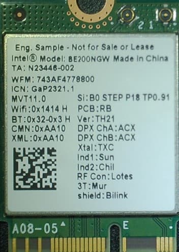
PD9BE200NG
Sep 13, 2023Intel BE200
Equipment Class
6CD - 15E 6 GHz Low Power Dual Client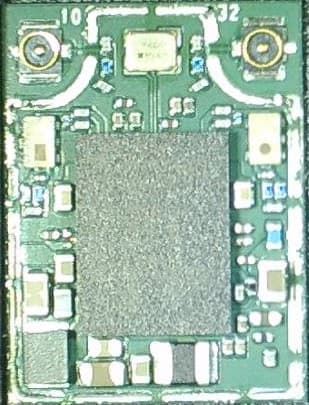
PD9BE200D2
Sep 13, 2023Intel BE200
Equipment Class
6CD - 15E 6 GHz Low Power Dual Client