PD96235ANHIntel Centrino Advanced-N 6235
Intel Corporation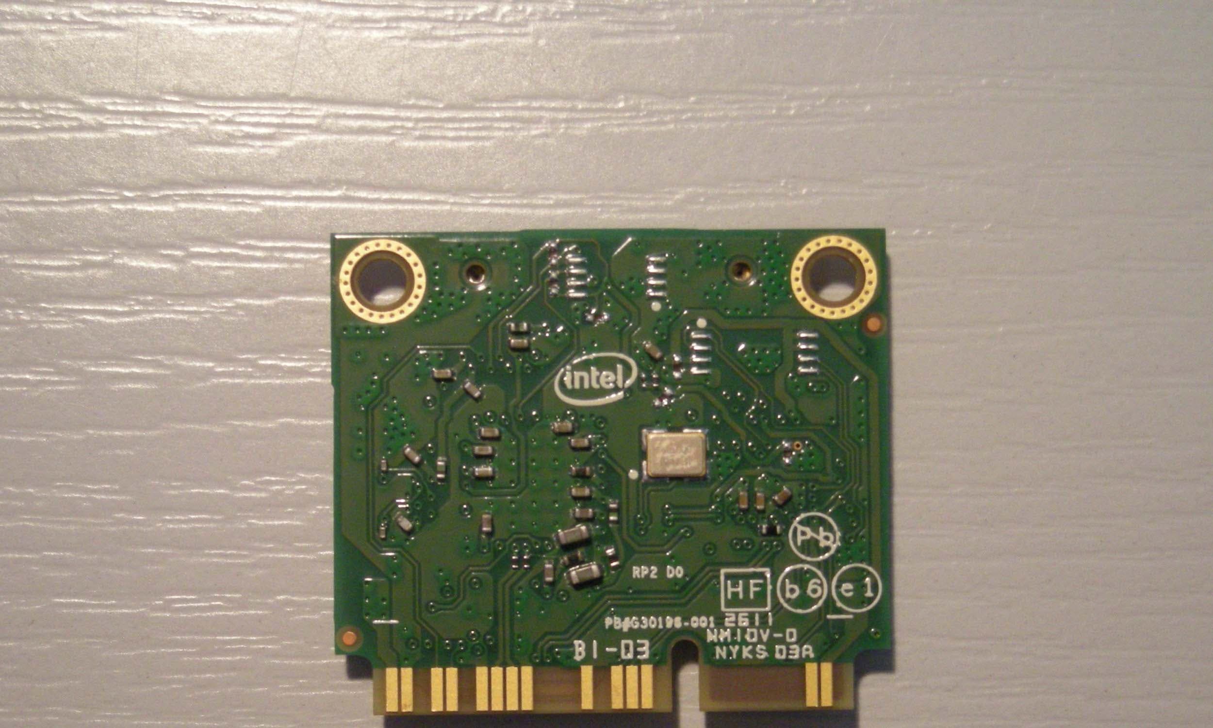
Click to zoom
Application Details
- Equipment Class
- DTS - Digital Transmission System
- Date of Grant
- Oct 10, 2011
- Application Purpose
- Original Equipment
- Date of Application
- Oct 10, 2011
- Equipment Note
- Intel Centrino Advanced-N 6235
- Frequency Range
- 2402.00000000 - 2480.00000000
- Company
- Intel Corporation
- Country
- France
Documents & Files
Document Text
Text extracted from the exhibit documents filed with the FCC. Open a document above to read the original.
Users Manual
Intel® Wireless Adapter Information Guide Supported wireless adapters: Intel® Centrino® Wireless-N 100 (Available for Windows* 7 only) Intel® Centrino® Wireless-N 105 (Available for Windows* 7 only) Intel® Centrino® Wireless-N 130 (Available for Windows* 7 only) Intel® Centrino® Wireless-N 135 (Available for Windows* 7 only) Intel® WiFi Link 1000 Intel® Centrino® Wireless-N 1030 Intel® Centrino® Wireless-N 2200 (Available for Windows* 7 only) Intel® Centrino® Wireless-N 2230 (Available for Windows* 7 only) Intel® Centrino® Wireless-N + WiMAX 6150 Intel® Centrino® Advanced-N 6200 Intel® Centrino® Advanced-N 6205 Intel® Centrino® Advanced-N 6230 Intel® Centrino® Advanced-N 6235 (Not available for Windows Vista) Intel® Centrino® Advanced-N + WiMAX 6250 Intel® Centrino® Ultimate-N 6300 With your WiFi network card, you can access WiFi networks, share files or printers, or even share your Internet connection. All of these features can be explored using a WiFi network in your home or office. This WiFi network solution is designed for both home and business use. Additional users and features can be added as your networking needs grow and change. This guide contains basic information about Intel adapters. It includes information about several adapter properties that you can set to control and enhance the performance of your adapter with your particular wireless network and environment. Intel® wireless adapters enable fast connectivity without wires for desktop and notebook PCs. Adapter Settings Regulatory Information Specifications Important Information Support Warranty Glossary Depending on the model of your Intel WiFi adapter, your adapter is compatible with 802.11a, 802.11b, 802.11g, and 802.11n (draft 2.0) wireless standards. Operating at 5 GHz or 2.4 GHz frequency at data rates of up to 450 Mbps, you can now connect your computer to existing high-speed networks that use multiple access points within large or small environments. Your WiFi adapter maintains automatic data rate control according to the access point location and signal strength to achieve the fastest possible connection. All of your wireless network connections are easily managed by the WiFi connection utility. Profiles that are set up through the WiFi connection utility provide enhanced security measures with 802.1X network authentication. Information in this document is subject to change without notice. © 2004–2011 Intel Corporation. All rights reserved. Intel Corporation, 5200 N.E. Elam Young Parkway, Hillsboro, OR 97124-6497 USA The copying or reproducing of any material in this document in any manner whatsoever without the written permission of Intel Corporation is strictly forbidden. Intel® is a trademark or registered trademark of Intel Corporation or its subsidiaries in the United States and other countries. Other trademarks and trade names may be used in this document to refer to either the entities claiming the marks and names or their products. Intel disclaims any proprietary interest in trademarks and trade names other than its own. Microsoft and Windows are registered trademarks of Microsoft Corporation. Windows Vista is either a registered trademark or trademark of Microsoft Corporation in the United States and/or other countries. *Other names and brands may be claimed as the property of others. Intel Corporation assumes no responsibility for errors or omissions in this document. Nor does Intel make any commitment to update the information contained herein. "IMPORTANT NOTICE FOR ALL USERS OR DISTRIBUTORS: Intel wireless LAN adapters are engineered, manufactured, tested, and quality checked to ensure that they meet all necessary local and governmental regulatory agency requirements for the regions that they are designated and/or marked to ship into. Because wireless LANs are generally unlicensed devices that share spectrum with radars, satellites, and other licensed and unlicensed devices, it is sometimes necessary to dynamically detect, avoid, and limit usage to avoid interference with these devices. In many instances Intel is required to provide test data to prove regional and local compliance to regional and governmental regulations before certification or approval to use the product is granted. Intel's wireless LAN's EEPROM, firmware, and software driver are designed to carefully control parameters that affect radio operation and to ensure electromagnetic compliance (EMC). These parameters include, without limitation, RF power, spectrum usage, channel scanning, and human exposure. For these reasons Intel cannot permit any manipulation by third parties of the software provided in binary format with the wireless LAN adapters (e.g., the EEPROM and firmware). Furthermore, if you use any patches, utilities, or code with the Intel wireless LAN adapters that have been manipulated by an unauthorized party (i.e., patches, utilities, or code (including open source code modifications) which have not been validated by Intel), (i) you will be solely responsible for ensuring the regulatory compliance of the products, (ii) Intel will bear no liability, under any theory of liability for any issues associated with the modified products, including without limitation, claims under the warranty and/or issues arising from regulatory non-compliance, and (iii) Intel will not provide or be required to assist in providing support to any third parties for such modified products. Note: Many regulatory agencies consider Wireless LAN adapters to be "modules", and accordingly, condition system-level regulatory approval upon receipt and review of test data documenting that the antennas and system configuration do not cause the EMC and radio operation to be non-compliant." September 7, 2011 Back to Contents Adapter Settings The Advanced tab displays the device properties for the WiFi adapter installed on your computer. How to Access At the Intel® PROSet/Wireless WiFi Connection Utility, Advanced Menu click Adapter Settings. Select the Advanced…
Text truncated - open the document above for the full version.
Attestation Statements
American Certification Body, Inc ACB, Inc. 6731 Whittier Avenue, Suite C110 • McLean, Virginia 22101 USA Ph: (703) 847-4700 • Fax: (703) 847-6888 www.ACBcert.com June 19, 2012 To whom it may concern; I attest to the fact that the documentation backs up the BLE band. It was an error on my part that it was not included in the original filing. The data for the BLE can be found on page 6 and from page 215 thru 237 of the DTS test report that was uploaded with the original filing. Thank you, Doug Noble ACB
Cover Letter(s)
Page 1 of 1 American TCB 6731 Whittier Avenue, Suite C110 McLean, VA. 22101 September 20, 2011 Ref: FCC ID PD96235ANH, Industry Canada 1000M-6235ANH To whom it may concern: The enclosed documents constitute a formal submittal and application for Equipment Authorization for an 802.11bgn / Bluetooth module pursuant to the following rules: Subpart B of Part 15 of FCC Rules (CFR 47) – Requirements for PC Peripherals Subpart C of Part 15 of FCC Rules (CFR 47) (15.247 for DTS and DSS) Subpart E of Part 15 of FCC Rules (CFR 47) RSS-Gen Issue 3, December 2010, “General Requirements and Information for the Certification of Radiocommunication Equipment” RSS-210, Issue 8, December 2010, “Low-power Licence-exempt Radiocommunication Devices (All Frequency Bands): Category I Equipment” For FCC purposes this is considered a composite device as it falls into equipment codes JBP, DTS, NII and DSS. Full modular approval is requested for this device. Elliott Laboratories, as duly authorized agent prepared this submittal. A copy of the letter of our appointment as agent is included with the application. If there are any questions or if further information is needed, please contact Elliott Laboratories for assistance. Sincerely, David W. Bare Chief Engineer
Cover Letter(s)
100 Center Point Circle Columbia, SC 29210 Authority to Act as Agent September 15, 2011 American Certification Body, Inc. 6731 Whittier Avenue Suite C110 McLean, VA 22101 To Whom It May Concern: NTS/Elliott Labs is authorized to act on our behalf, until otherwise notified, for applications to American Certification Body, Inc. (ACB). We certify that we are not subject to denial of federal benefits, that includes FCC benefits, pursuant to Section 5301 of the Anti-Drug Abuse Act of 1988, 21 U.S.C. 862. Further, no party, as defined in 47 CFR 1.2002 (b), to the application is subject to denial of federal benefits, that includes FCC benefits. Thank you, Agency Agreement Expiration Date: September 15, 2012 By: Steven C. Hackett (Signature 1 ) (Print name) Title: Wireless Regulations Engineer On behalf of: Intel Corporation (Company Name) Telephone: 803-216-2344
Cover Letter(s)
100 Center Point Circle Columbia, SC 29210 September 15, 2011 Subject: Confidentiality Request for FCC ID: PD96235ANH and PD96235ANHU Pursuant to FCC 47 CRF 0.457(d) and 0.459 and IC RSP-100, Section 10, the applicant requests that a part of the subject FCC application be held confidential. Type of Confidentiality Requested Exhibit Short Term Permanent Block Diagrams Short Term External Photos Short Term Permanent* 1 Internal Photos Short Term Permanent Operation Description/Antenna Specification Short Term Permanent Operation Description/HW Theory of Operation Short Term Permanent Operational Description/BiOS Lock Description Short Term Permanent Operational Description/BT FHSS Description Short Term Permanent Schematics Short Term Test Setup Photos Short Term Permanent* User’s Manual Intel Corporation has spent substantial effort in developing this product and it is one of the first of its kind in industry. Having the subject information easily available to "competition" would negate the advantage they have achieved by developing this product. Not protecting the details of the design will result in financial hardship. Permanent Confidentiality: The applicant requests the exhibits listed above as permanently confidential be permanently withheld from public review due to materials that contain trade secrets and proprietary information not customarily released to the public. Short-Term Confidentiality: The applicant requests the exhibits selected above as short term confidential be withheld from public view for a period of 180 days from the date of the Grant of Equipment Authorization and prior to marketing. This is to avoid premature release of sensitive information prior to marketing or release of the product to the public. Applicant is also aware that they are responsible to notify ATCB in the event information regarding the product or the product is made available to the public. ATCB will then release the documents listed above for public disclosure pursuant to FCC Public Notice DA 04- 1705. Sincerely, Steven C. Hackett By: __________________________ ________________________ (Signature/Title 2 ) (Print Name) 1 - The asterisked items (*) require further justification before permanent confidentiality will be allowed. These also currently require review by the FCC under their Permit-But-Ask policy before the grant is issued and can delay completion of an application. Further justification should be added to the note above. One such example for a potted device would be: “The EUT is FULLY potted using a non-removable epoxy based material. Removal of potting material causes irreparable damage to internal circuitry. See photographs exhibits that outline the device before and after potting.” 2 - Must be signed by applicant contact given for applicant on the FCC site, or by the authorized agent if an appropriate authorized agent letter has been provided. Letters should be placed on appropriate letterhead.
Cover Letter(s)
Intel Corporation 100 Center Point Circle Columbia, SC 29210 Modular Approval Requirements Attestation FCC ID: PD96235ANH IC: 1000M-6235ANH Modular Approval is being requested for this device under the ID’s listed above. This device is a self contained, physically delineated, component for which compliance was demonstrated independent of any host operating conditions and complies with all eight requirements of FCC Part 15.212(a)(1) and IC RSS-GEN, 3.2.2. The details of these requirements and the manner in which the devices meet them are summarized below. The module must have its own RF shielding. The module contains a metal shield which covers all RF components and circuitry; this shield is located on the top side of the board located next to the antenna connectors. All modulation and data input(s) are buffered. Data to the modulation circuit is buffered on the module; please refer to the “theory of operation” document filed with this application for full description. The module has its own power supply regulation and local reference oscillator. The module contains its own power supply regulation and the rf reference oscillator is contained within the module. Please refer to the schematics and “theory of operation” documents filed with this application for full description. The modular transmitter must comply with the antenna requirements of Section 15.203 and 15.204(c). The certification submission contains a detailed description of all antennas that will be used with the module. The module connects to its antenna via using an UFL type connector. This antenna connector is a non-standard connector. The antenna tested was a PIFA type and the data sheet is included in the application. The modular transmitter must be tested in a stand-alone configuration, i.e., the module must not be inside another device during testing. Test data contained in this application is for the device tested as a stand-alone device connected externally to a PC. See test set-up photographs filed with this application. For the FCC, the modular transmitter must be labeled with its own FCC ID number, and, if the FCC ID is not visible when the module is installed inside another device, then the outside Intel Corporation 100 Center Point Circle Columbia, SC 29210 of the device into which the module is installed must also display a label referring to the enclosed module. This exterior label can use wording such as the following: “Contains Transmitter Module FCC ID: XYZMODEL1” or “Contains FCC ID: XYZMODEL1.” For Industry Canada, the module meets certification labeling requirements for Category I Equipment. The module is appropriately labeled (refer to the label and label location drawings contained within this application). Information to the integrator of this device regarding the labeling requirements for the host system is contained in the instructions provided with the module. The modular transmitter must comply with any applicable RF exposure requirements. The module meets the requirements for a mobile device that may be used at separation distances of more than 20cm from the human body. Refer to the MPE calculation data sheet.
ID Label/Location Info
Photos shows label placement on half‐mini card Label wraps around onto the other side of the board. The side of the label with the FCC ID appears on the back of the board.
RF Exposure Info
802 N. Twin Oaks Valley Road, Suite 105 • San Marcos, CA 92069 • U.S.A. TEL (760) 471-2100 • FAX (760) 471-2121 http://www.rfexposurelab.com CERTIFICATE OF COMPLIANCE SAR EVALUATION Intel Corporation Dates of Test: Aug. 30-Sep. 1, 2011 100 Center Point Circle, Suite 200 Test Report Number: SAR.20110901 Columbia, SC 29210 FCC ID: PD96235ANH and PD96235ANHU IC Certificate: 1000M-6235ANH and 1000M-6235ANHU Model(s): Intel® Centrino® Advanced-N 6235 (Model 6235ANHMW & 6235ANHU) Test Sample: Engineering Unit Same as Production MAC Address: 44850001D0DD Equipment Type: Wireless Module Classification: Portable Transmitter Next to Body TX Frequency Range: 2412 – 2462 MHz; 5180 – 5320 MHz; 5500 – 5700 MHz; 5745 – 5825 MHz Frequency Tolerance: ± 2.5 ppm Maximum RF Output: 2450 MHz (b) – 16.84 dB, 2450 MHz (g) – 15.88 dB, 2450 MHz (n20) – 15.51 dB, 2450 MHz (n40) – 12.41 dB, 5250 MHz (a) – 16.40 dB, 5250 MHz (n20) – 16.32 dB, 5250 MHz (n40) – 16.30 dB, 5600 MHz (a) – 16.45 dB, 5600 MHz (n20) – 16.41 dB, 5600 MHz (n40) – 16.41 dB, 5800 MHz (a) – 16.50 dB, 5800 MHz (n20) – 16.47 dB, 5800 MHz (n40) – 16.45 dB Conducted Signal Modulation: DSSS, OFDM Antenna Type: Shanghai Universe Communications Electron Co., Ltd., PIFA Antenna Application Type: Certification FCC Rule Parts: Part 2, 15C, 15E KDB Test Methodology: KDB 447498, KDB 248227, KDB 616217 Industry Canada: RSS-102, Safety Code 6 Maximum SAR Value: 0.389 W/kg Separation Distance: 12 mm This wireless mobile and/or portable device has been shown to be compliant for localized specific absorption rate (SAR) for uncontrolled environment/general exposure limits specified in ANSI/IEEE Std. C95.1-1992 and had been tested in accordance with the measurement procedures specified in IEEE 1528-2003, and OET Bulletin 65 Supp. C (See test report). I attest to the accuracy of the data. All measurements were performed by myself or were made under my supervision and are correct to the best of my knowledge and belief. I assume full responsibility for the completeness of these measurements and vouch for the qualifications of all persons taking them. RF Exposure Lab, LLC certifies that no party to this application is subject to a denial of Federal benefits that includes FCC benefits pursuant to Section 5301 of the Anti-Drug Abuse Act of 1988, 21 U.S.C. 853(a). Jay M. Moulton Vice President Certificate # 2387.01 © 2011 RF Exposure Lab, LLC This report shall not be reproduced except in full without the written approval of RF Exposure Lab, LLC. FCC ID: PD96235ANH Table of Contents 1. Introduction ........................................................................................................................... 3 SAR Definition [5] ...................................................................................................................... 3 2. SAR Measurement Setup ..................................................................................................... 4 Robotic System ......................................................................................................................... 4 System Hardware ..................................................................................................................... 4 System Description ................................................................................................................... 4 E-Field Probe ............................................................................................................................ 5 3. Robot Specifications ............................................................................................................. 7 4. Probe and Dipole Calibration ................................................................................................ 8 5. Phantom & Simulating Tissue Specifications ........................................................................ 9 SAM Phantom ........................................................................................................................... 9 Head & Body Simulating Mixture Characterization ................................................................... 9 Device Holder ........................................................................................................................... 9 6. ANSI/IEEE C95.1 – 1992 RF Exposure Limits [2] ............................................................... 10 Uncontrolled Environment ....................................................................................................... 10 Controlled Environment .......................................................................................................... 10 7. Measurement Uncertainty ................................................................................................... 11 8. System Validation ............................................................................................................... 12 Tissue Verification ................................................................................................................... 12 Test System Verification ......................................................................................................... 12 9. SAR Test Data Summary .................................................................................................... 13 Procedures Used To Establish Test Signal ............................................................................. 13 Device Test Condition ............................................................................................................. 13 SAR Data Summary – 2450 MHz Body 802.11b .................................................................... 18 SAR Data Summary – 2450 MHz Body 802.11b .................................................................... 18 SAR Data Summary – 5150 MHz Body 802.11a .................................................................... 19 SAR Data Summary – 5250 MHz Body 802.11a .....................…
Text truncated - open the document above for the full version.
Test Report
File: R84671 Page 1 EMC Test Report Industry Canada RSS-Gen Issue 2 / RSS 210 Issue 7 FCC Part 15 Subpart C Intel® Centrino® Advanced-N 6235, models 6235ANHMW and 6235ANHU IC CERTIFICATION #: 1000M-6235ANH and 1000M-6235ANHU FCC ID: PD96235ANH and PD96235ANHU APPLICANT: Intel Corporation 100 Center Point Circle Suite 200 Columbia, SC 29210 TEST SITE(S): Elliott Laboratories 41039 Boyce Road. Fremont, CA. 94538-2435 IC SITE REGISTRATION #: 2845B-4, 2845-5, 2845B-7 REPORT DATE: September 27, 2011 FINAL TEST DATES: September 13-17, 20, 21, 28, 29, 30, October 1, 4, 2010, August 31, 2011, September 2 and 8, 2011 TOTAL NUMBER OF PAGES: 237 PROGRAM MGR / QUALITY ASSURANCE DELEGATE / TECHNICAL REVIEWER: FINAL REPORT PREPARER: ______________________________ ______________________________ David W. Bare David Guidotti Chief Engineer Senior Technical Writer Elliott Laboratories is accredited by the A2LA, certificate number 2016.01, to perform the test(s) listed in this report, except where noted otherwise. This report and the information contained herein represent the results of testing test articles identified and selected by the client performed to specifications and/or procedures selected by the client. National Technical Systems (NTS) makes no representations, expressed or implied, that such testing is adequate (or inadequate) to demonstrate efficiency, performance, reliability, or any other characteristic of the articles being tested, or similar products. This report should not be relied upon as an endorsement or certification by NTS of the equipment tested, nor does it represent any statement whatsoever as to its merchantability or fitness of the test article, or similar products, for a particular purpose. This report shall not be reproduced except in full Elliott Laboratories -- EMC Department Test Report Report Date: September 27, 2011 File: R84671 Page 2 REVISION HISTORY Rev# Date Comments Modified By - 09-27-2011 First release Elliott Laboratories -- EMC Department Test Report Report Date: September 27, 2011 File: R84671 Page 3 TABLE OF CONTENTS REVISION HISTORY ................................................................................................................................................2 TABLE OF CONTENTS ............................................................................................................................................3 SCOPE..........................................................................................................................................................................4 OBJECTIVE ................................................................................................................................................................4 STATEMENT OF COMPLIANCE...........................................................................................................................5 DEVIATIONS FROM THE STANDARDS ..............................................................................................................5 TEST RESULTS SUMMARY ...................................................................................................................................6 DIGITAL TRANSMISSION SYSTEMS (2400 – 2483.5MHZ) ..............................................................................6 DIGITAL TRANSMISSION SYSTEMS (5725 –5850 MHZ) .................................................................................6 GENERAL REQUIREMENTS APPLICABLE TO ALL BANDS..........................................................................7 ADDITIONAL MEASUREMENTS ........................................................................................................................7 MEASUREMENT UNCERTAINTIES....................................................................................................................8 EQUIPMENT UNDER TEST (EUT) DETAILS ......................................................................................................9 GENERAL................................................................................................................................................................9 ANTENNA SYSTEM ..............................................................................................................................................9 ENCLOSURE...........................................................................................................................................................9 MODIFICATIONS...................................................................................................................................................9 SUPPORT EQUIPMENT.......................................................................................................................................10 EUT INTERFACE PORTS ....................................................................................................................................10 EUT OPERATION .................................................................................................................................................10 TEST SITE.................................................................................................................................................................12 GENERAL INFORMATION .................................................................................................................................12 CONDUCTED EMISSIONS CONSIDERATIONS ..............................................................................................12 RADIATED EMISSIONS CONSIDERATIONS ..................................................................................................12 MEASUREMENT INSTRUMENTATION ............................................................................................................13 RECEIVER SYSTEM ...........................................................................................................................…
Text truncated - open the document above for the full version.
Test Setup Photos
Test Configuration – Wireless Module Radiated Emissions AC Conducted Emissions AC Conducted Emissions
Contact Information
Applicant
Benjamin Lavenant(Regulatory Engineer)
Technical Contact
Intel CorporationSteven Hackett
[email protected]803 216 2344
100 Center Point Circle Suite 200 · Columbia · United States
Test Firm
Elliott Laboratories LLCDavid Bare
Technical Specifications
| # | Rule Parts | Frequency Range | Power Output |
|---|---|---|---|
| 5 | 15C | 2.40 GHz - 2.48 GHz | 4.80 mW |
Other Applications from Intel Corporation
PD9BE201D2P
Aug 20, 2024Intel BE201D2WP
Equipment Class
NII - Unlicensed National Information Infrastructure TXPD9AX411NG
Jul 02, 2024Intel WiFi 6E AX411
Equipment Class
6CD - 15E 6 GHz Low Power Dual ClientPD9AX211D2H
Jan 28, 2024Intel Wi-Fi 6E AX211
Equipment Class
DSS - Part 15 Spread Spectrum Transmitter
PD9BE200NG
Sep 13, 2023Intel BE200
Equipment Class
6CD - 15E 6 GHz Low Power Dual Client
PD9BE200D2
Sep 13, 2023Intel BE200
Equipment Class
6CD - 15E 6 GHz Low Power Dual Client