PD97260NGModel 7260NGW Wireless Network Adapter
Intel Corporation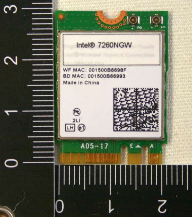
Click to zoom
Application Details
- Equipment Class
- DTS - Digital Transmission System
- Date of Grant
- Apr 16, 2013
- Application Purpose
- Original Equipment
- Date of Application
- Apr 16, 2013
- Equipment Note
- Model 7260NGW Wireless Network Adapter
- Frequency Range
- 5755.00000000 - 5795.00000000
- Company
- Intel Corporation
- Country
- France
Documents & Files
Document Text
Text extracted from the exhibit documents filed with the FCC. Open a document above to read the original.
Users Manual
Intel® Wireless Adapter Information Guide This version of Intel® PROSet/Wireless WiFi Software is compatible with the adapters listed next. Note that when using the Adminstrator Tool, the intention is to create packages and profiles to be exported to client computers that may be using other Intel® wireless adapter not listed here. Intel® Dual Band Wireless-AC 7260 Intel® Dual Band Wireless-N 7260 Intel® Wireless-N 7260 With your WiFi network card, you can access WiFi networks, share files or printers, or even share your Internet connection. All of these features can be explored using a WiFi network in your home or office. This WiFi network solution is designed for both home and business use. Additional users and features can be added as your networking needs grow and change. This guide contains basic information about Intel adapters. It includes information about several adapter properties that you can set to control and enhance the performance of your adapter with your particular wireless network and environment. Intel® wireless adapters enable fast connectivity without wires for desktop and notebook PCs. Adapter Settings Regulatory Information Specifications Important Information Support Warranty Glossary Depending on the model of your Intel WiFi adapter, your adapter is compatible with 802.11a, 802.11b, 802.11g, and 802.11n (draft 2.0) wireless standards. Operating at 5GHz or 2.4GHz frequency at data rates of up to 450 Mbps, you can now connect your computer to existing high- speed networks that use multiple access points within large or small environments. Your WiFi adapter maintains automatic data rate control according to the access point location and signal strength to achieve the fastest possible connection. All of your wireless network connections are easily managed by the WiFi connection utility. Profiles that are set up through the WiFi connection utility provide enhanced security measures with 802.1X network authentication. Information in this document is subject to change without notice. © 2004–2012 Intel Corporation. All rights reserved. Intel Corporation, 5200 N.E. Elam Young Parkway, Hillsboro, OR 97124-6497 USA The copying or reproducing of any material in this document in any manner whatsoever without the written permission of Intel Corporation is strictly forbidden. Intel® is a trademark or registered trademark of Intel Corporation or its subsidiaries in the United States and other countries. Other trademarks and trade names may be used in this document to refer to either the entities claiming the marks and names or their products. Intel disclaims any proprietary interest in trademarks and trade names other than its own. Microsoft and Windows are registered trademarks of Microsoft Corporation. Windows Vista is either a registered trademark or trademark of Microsoft Corporation in the United States and/or other countries. *Other names and brands may be claimed as the property of others. Intel Corporation assumes no responsibility for errors or omissions in this document. Nor does Intel make any commitment to update the information contained herein. "IMPORTANT NOTICE FOR ALL USERS OR DISTRIBUTORS: Intel wireless LAN adapters are engineered, manufactured, tested, and quality checked to ensure that they meet all necessary local and governmental regulatory agency requirements for the regions that they are designated and/or marked to ship into. Because wireless LANs are generally unlicensed devices that share spectrum with radars, satellites, and other licensed and unlicensed devices, it is sometimes necessary to dynamically detect, avoid, and limit usage to avoid interference with these devices. In many instances Intel is required to provide test data to prove regional and local compliance to regional and governmental regulations before certification or approval to use the product is granted. Intel's wireless LAN's EEPROM, firmware, and software driver are designed to carefully control parameters that affect radio operation and to ensure electromagnetic compliance (EMC). These parameters include, without limitation, RF power, spectrum usage, channel scanning, and human exposure. For these reasons Intel cannot permit any manipulation by third parties of the software provided in binary format with the wireless LAN adapters (e.g., the EEPROM and firmware). Furthermore, if you use any patches, utilities, or code with the Intel wireless LAN adapters that have been manipulated by an unauthorized party (i.e., patches, utilities, or code (including open source code modifications) which have not been validated by Intel), (i) you will be solely responsible for ensuring the regulatory compliance of the products, (ii) Intel will bear no liability, under any theory of liability for any issues associated with the modified products, including without limitation, claims under the warranty and/or issues arising from regulatory non-compliance, and (iii) Intel will not provide or be required to assist in providing support to any third parties for such modified products. Note: Many regulatory agencies consider Wireless LAN adapters to be "modules", and accordingly, condition system-level regulatory approval upon receipt and review of test data documenting that the antennas and system configuration do not cause the EMC and radio operation to be non-compliant." January 28, 2013 Back to Contents Adapter Settings The Advanced tab displays the device properties for the WiFi adapter installed on your computer. How to Access At the Intel® PROSet/Wireless WiFi Connection Utility, Advanced Menu click Adapter Settings. Select the Advanced tab. WiFi Adapter Settings Description Note: Not all settings described are available for all adapters. You may not see all settings listed here. Name Description 802.11ac Mode (5GHz) The 802.11ac standard builds on 802.11n standard. 802.11ac Mode delivers up to 867Mbps (theoretical) by increasing channel bandwidth to 80MHz and adding higher density…
Text truncated - open the document above for the full version.
Cover Letter(s)
100 Center Point Circle Columbia, SC 29210 Authority to Act as Agent March 4, 2013 American Certification Body, Inc. 6731 Whittier Avenue Suite C110 McLean, VA 22101 To Whom It May Concern: TÜV Rheinland EPS B.V. is authorized to act on our behalf, until otherwise notified, for applications to American Certification Body, Inc. (ACB). We certify that we are not subject to denial of federal benefits, that includes FCC benefits, pursuant to Section 5301 of the Anti-Drug Abuse Act of 1988, 21 U.S.C. 862. Further, no party, as defined in 47 CFR 1.2002 (b), to the application is subject to denial of federal benefits, that includes FCC benefits. Thank you, Agency Agreement Expiration Date: March 4, 2014 By: Steven C. Hackett (Signature 1 ) (Print name) Title: Wireless Regulations Engineer On behalf of: Intel Corporation (Company Name) Telephone: 803-216-2344
Cover Letter(s)
100 Center Point Circle Columbia, SC 29210 March 4, 2013 Subject: Confidentiality Request for FCC ID: PD97260NG Pursuant to FCC 47 CRF 0.457(d) and 0.459 the applicant requests that a part of the subject FCC application be held confidential. Type of Confidentiality Requested Exhibit Short Term Permanent Block Diagrams Short Term External Photos Short Term Permanent Internal Photos Short Term Permanent Operation Description/Antenna Specification Short Term Permanent Operation Description/HW Theory of Operation Short Term Permanent Operational Description/BiOS Lock Description Short Term Permanent Operational Description/BT FHSS Description Short Term Permanent Schematics Short Term Permanent Bill of Materials Short Term Test Setup Photos Short Term Permanent User’s Manual Intel Corporation has spent substantial effort in developing this product and it is one of the first of its kind in industry . Having the subject information easily available to "competition" would negate the advantage they have achieved by developing t his product. Not protecting the details of the design will result in financial hardship. Permanent Confidentiality: The applicant requests the exhibits listed above as perm anently confidential be permanently withheld from public review due to materials that contain trade secrets and proprietary information not customarily released to the public. Short-Term Confidentiality: The applicant requests the exhibits selected above as short term confidential be withheld from public view for a period of 180 days from the date of the Grant of Equipment Authorization and prior to marketing. This is to avoid premature release of sensitive inform at ion prior to marketing or re lease of the prod uct to the public. Applicant is also aware that they are responsible to notify ATCB in the event inform ation regarding the product or the product is made available to the public. ATCB will then release the documents listed above for public disclosure pursuant to FCC Public Notice DA 04- 1705. Sincerely, Steven C. Hackett By: __________________________ ________________________ (Signature/Title 1 ) (Print Name)
Cover Letter(s)
Intel Corporation 100 Center Point Circle Columbia, SC 29210 Modular Approval Requirements Attestation FCC ID: PD97260NG Modular Approval is being requested for this device under the ID’s listed above. This device is a self contained, physically delineated, component for which compliance was demonstrated independent of any host operating conditions and complies with all eight requirements of FCC Part 15.212(a)(1) and IC RSS-GEN, 3.2.2. The details of these requirements and the manner in which the devices meet them are summarized below. The module must have its own RF shielding. The module contains a metal shield which covers all RF components and circuitry; this shield is located on the top side of the board located next to the antenna connectors. All modulation and data input(s) are buffered. Data to the modulation circuit is buffered on the module; please refer to the “theory of operation” document filed with this application for full description. The module has its own power supply regulation and local reference oscillator. The module contains its own power supply regulation and the rf reference oscillator is contained within the module. Please refer to the schematics and “theory of operation” documents filed with this application for full description. The modular transmitter must comply with the antenna requirements of Section 15.203 and 15.204(c). The certification submission contains a detailed description of all antennas that will be used with the module. The module connects to its antenna via using an UFL type connector. This antenna connector is a non-standard connector. The antenna tested was a PIFA type and the data sheet is included in the application. The modular transmitter must be tested in a stand-alone configuration, i.e., the module must not be inside another device during testing. Test data contained in this application is for the device tested as a stand-alone device connected externally to a PC. See test set-up photographs filed with this application. For the FCC, the modular transmitter must be labeled with its own FCC ID number, and, if the FCC ID is not visible when the module is installed inside another device, then the outside of the device into which the module is installed must also display a label referring to the Intel Corporation 100 Center Point Circle Columbia, SC 29210 enclosed module. This exterior label can use wording such as the following: “Contains Transmitter Module FCC ID: XYZMODEL1” or “Contains FCC ID: XYZMODEL1.” For Industry Canada, the module meets certification labeling requirements for Category I Equipment. The module is appropriately labeled (refer to the label and label location drawings contained within this application). Information to the integrator of this device regarding the labeling requirements for the host system is contained in the instructions provided with the module. The modular transmitter must comply with any applicable RF exposure requirements. The module meets the requirements for a mobile/portable device that may be used at separation distances of more than 8mm from the human body. Refer to the RF Exposure test report submitted with this application.
External Photos
Testing and certification of electronic and electric appliances, systems, installations and telecommunication systems TÜV Rheinland EPS B.V. P.O. Box 37 9350AA Leek (NL) Eiberkamp 10 9351VT Leek (NL) Telephone: +31 594 505005 Telefax: +31 594 504804 Internet: www.tuv-eps.com E-mail: [email protected] Project number: 12121201.p02 Page 1 of 5 PHOTOGRAPHS OF THE EXTERIOR OF A WIRELESS NETWORK ADAPTER MODULE, BRAND INTEL, MODEL 7260NGW FCC listed Industry Canada VCCI Registered R&TTE, LVD, EMC Notified Body : : : : 90828 2932G-2 R-1518, C-1598 1856 Description of EUT: Manufacturer: Brand mark: Model: FCC ID: IC: Wireless Network Adapter Module Intel Corporation Intel 7260NGW PD97260NG and PD97260NGU 1000M-7260NG Project number: 12121201.p02 Page 2 of 5 Description of test item Test item : Wireless Network Adapter Module Manufacturer : Intel Corporation Brand : Intel Model(s) : 7260NGW Serial number(s) : 001500B6698F Revision : n.a. Receipt date : January 07, 2013 Applicant information Applicant's representative : Mr. Steven Hackett Company : Intel Corporation Address : 100 Center Point Circle Suite 200 Postal code : 29210 City : State Columbia South Carolina Country : United States of America Telephone number : 803-216-2344 Description of EUT: Manufacturer: Brand mark: Model: FCC ID: IC: Wireless Network Adapter Module Intel Corporation Intel 7260NGW PD97260NG and PD97260NGU 1000M-7260NG Project number: 12121201.p02 Page 3 of 5 Table of contents 1 PHOTOGRAPHS OF THE EQUIPMENT. ....................................................................................................................... 4 1.1 EXTERNAL VIEW. ............................................................................................................................................................ 4 1.1.1 Front view.............................................................................................................................................................. 4 1.1.2 Rear view .............................................................................................................................................................. 5 Description of EUT: Manufacturer: Brand mark: Model: FCC ID: IC: Wireless Network Adapter Module Intel Corporation Intel 7260NGW PD97260NG and PD97260NGU 1000M-7260NG Project number: 12121201.p02 Page 4 of 5 1 Photographs of the equipment. 1.1 External view. 1.1.1 Front view Description of EUT: Manufacturer: Brand mark: Model: FCC ID: IC: Wireless Network Adapter Module Intel Corporation Intel 7260NGW PD97260NG and PD97260NGU 1000M-7260NG Project number: 12121201.p02 Page 5 of 5 1.1.2 Rear view
ID Label/Location Info
7260NGW Label & Location, FCC ID: PD97260NG
Internal Photos
Testing and certification of electronic and electric appliances, systems, installations and telecommunication systems TÜV Rheinland EPS B.V. P.O. Box 37 9350AA Leek (NL) Eiberkamp 10 9351VT Leek (NL) Telephone: +31 594 505005 Telefax: +31 594 504804 Internet: www.tuv-eps.com E-mail: [email protected] Project number: 12121201.p01 Page 1 of 7 PHOTOGRAPHS OF THE INTERIOR OF A WIRELESS NETWORK ADAPTER MODULE, BRAND INTEL, MODEL 7260NGW FCC listed Industry Canada VCCI Registered R&TTE, LVD, EMC Notified Body : : : : 90828 2932G-2 R-1518, C-1598 1856 Description of EUT: Manufacturer: Brand mark: Model: FCC ID: IC: Wireless Network Adapter Module Intel Corporation Intel 7260NGW PD97260NG and PD97260NGU 1000M-7260NG Project number: 12121201.p01 Page 2 of 7 Description of test item Test item : Wireless Network Adapter Module Manufacturer : Intel Corporation Brand : Intel Model : 7260NGW Serial number(s) : 001500B6698F Revision : n.a. Receipt date : January 07, 2013 Applicant information Applicant's representative : Mr. Steven Hackett Company : Intel Corporation Address : 100 Center Point Circle Suite 200 Postal code : 29210 City : State Columbia South Carolina Country : United States of America Telephone number : 803-216-2344 Description of EUT: Manufacturer: Brand mark: Model: FCC ID: IC: Wireless Network Adapter Module Intel Corporation Intel 7260NGW PD97260NG and PD97260NGU 1000M-7260NG Project number: 12121201.p01 Page 3 of 7 Table of contents 1.1 FRONT VIEW, SHIELDED EUT. ........................................................................................................................................ 4 1.2 FRONT VIEW, UNSHIELDED EUT. ................................................................................................................................... 5 1.3 BACK VIEW EUT. ............................................................................................................................................................ 6 1.4 BACK VIEW EUT, LABEL REMOVED. ............................................................................................................................... 7 Description of EUT: Manufacturer: Brand mark: Model: FCC ID: IC: Wireless Network Adapter Module Intel Corporation Intel 7260NGW PD97260NG and PD97260NGU 1000M-7260NG Project number: 12121201.p01 Page 4 of 7 1.1 Front view, shielded EUT. Description of EUT: Manufacturer: Brand mark: Model: FCC ID: IC: Wireless Network Adapter Module Intel Corporation Intel 7260NGW PD97260NG and PD97260NGU 1000M-7260NG Project number: 12121201.p01 Page 5 of 7 1.2 Front view, unshielded EUT. Description of EUT: Manufacturer: Brand mark: Model: FCC ID: IC: Wireless Network Adapter Module Intel Corporation Intel 7260NGW PD97260NG and PD97260NGU 1000M-7260NG Project number: 12121201.p01 Page 6 of 7 1.3 Back view EUT. Description of EUT: Manufacturer: Brand mark: Model: FCC ID: IC: Wireless Network Adapter Module Intel Corporation Intel 7260NGW PD97260NG and PD97260NGU 1000M-7260NG Project number: 12121201.p01 Page 7 of 7 1.4 Back view EUT, label removed.
Parts List/Tune Up Info
Intel Corporation 100 Center Point Circle Columbia, SC 29210 March 4, 2013 American Certification Body 6731 Whittier Avenue Suite C110 McLean, VA 22101 USA Subject: Model 7260NGW 802.11a/b/g/n/ac WiFi/Bluetooth Combo PCIe Adapter Card FCC ID’s: PD97260NG and PD97260NGU Gentlemen: Please be advised that for the Model 7260NGW adapter card all final calibrated output power adjustments are made during the assembly process and all maximum output power levels and operational parameters are programmed into the EEPROM prior to shipment from the factory. The information programmed into the EEPROM is not accessible and can not be changed by OEMs or end users. There are no OEM or end user installation adjustments that can be made therefore there is no tune-up procedure provided. If you have any questions please do not hesitate to contact us at 803-216-2344. Sincerely, Steven C. Hackett Wireless Regulatory Engineer
RF Exposure Info
802 N. Twin Oaks Valley Road, Suite 105 • San Marcos, CA 92069 • U.S.A. TEL (760) 471-2100 • FAX (760) 471-2121 http://www.rfexposurelab.com CERTIFICATE OF COMPLIANCE SAR EVALUATION Intel Corporation Dates of Test: Jan. 25-Feb. 2, 2013 100 Center Point Circle, Suite 200 Test Report Number: SAR.20130203 Columbia, SC 29210 This wireless mobile and/or portable device has been shown to be compliant for localized specific absorption rate (SAR) for uncontrolled environment/general exposure limits specified in ANSI/IEEE Std. C95.1-1992 and had been tested in accordance with the measurement procedures specified in IEEE 1528-2003, IEC 62209-2 and OET Bulletin 65 Supp. C (See test report). I attest to the accuracy of the data. All measurements were performed by myself or were made under my supervision and are correct to the best of my knowledge and belief. I assume full responsibility for the completeness of these measurements and vouch for the qualifications of all persons taking them. RF Exposure Lab, LLC certifies that no party to this application is subject to a denial of Federal benefits that includes FCC benefits pursuant to Section 5301 of the Anti-Drug Abuse Act of 1988, 21 U.S.C. 853(a). Jay M. Moulton Vice President Certificate # 2387.01 FCC ID: PD97260NG & PD97260NGU IC Certificate: 1000M-7260NG Model(s): 7260NGW Test Sample: Engineering Unit Same as Production MAC Address: 001500B664F3 Equipment Type: Wireless Module Classification: Portable Transmitter Next to Body TX Frequency Range: 2412 – 2462 MHz; 5180 – 5320 MHz; 5500 – 5700 MHz; 5745 – 5825 MHz Frequency Tolerance: ± 2.5 ppm Maximum RF Output: 2450 MHz (b) – 15.50 dB, 2450 MHz (g) – 16.50 dB, 2450 MHz (n20) – 16.50 dB, 2450 MHz (n40) – 16.50 dB, 5250 MHz (a) – 16.00 dB, 5250 MHz (n20) – 16.00 dB, 5250 MHz (n40) – 15.50 dB, 5250 MHz (ac) – 11.00 dB, 5600 MHz (a) – 16.50 dB, 5600 MHz (n20) – 16.50 dB, 5600 MHz (n40) – 16.50 dB, 5600 MHz (ac) – 16.50 dB, 5800 MHz (a) – 16.50 dB, 5800 MHz (n20) – 16.50 dB, 5800 MHz (n40) – 16.50 dB 5800 MHz (ac) – 14.00 dB Conducted Signal Modulation: DSSS, OFDM Antenna Type: Skycross Electronics (Shenzhen) Co., Ltd., PIFA Antenna Application Type: Certification FCC Rule Parts: Part 2, 15C, 15E KDB Test Methodology: KDB 447498 D01 v05, KDB 248227 v01r02, KDB 616217 D04 v01 Industry Canada: RSS-102, Safety Code 6 Maximum SAR Value: 0.757 W/kg Separation Distance: 8 mm © 2013 RF Exposure Lab, LLC This report shall not be reproduced except in full without the written approval of RF Exposure Lab, LLC. FCC ID: PD97260NG Table of Contents 1. Introduction ........................................................................................................................ 3 SAR Definition [5] ................................................................................................................... 4 2. SAR Measurement Setup ................................................................................................... 5 Robotic System ...................................................................................................................... 5 System Hardware ................................................................................................................... 5 System Description ................................................................................................................ 5 E-Field Probe ......................................................................................................................... 6 3. Robot Specifications ........................................................................................................... 8 4. Probe and Dipole Calibration .............................................................................................. 9 5. Phantom & Simulating Tissue Specifications .....................................................................10 Head & Body Simulating Mixture Characterization ................................................................10 6. ANSI/IEEE C95.1 – 1992 RF Exposure Limits [2] ..............................................................11 Uncontrolled Environment .....................................................................................................11 Controlled Environment .........................................................................................................11 7. Measurement Uncertainty .................................................................................................12 8. System Validation..............................................................................................................13 Tissue Verification .................................................................................................................13 Test System Verification ........................................................................................................13 9. SAR Test Data Summary ..................................................................................................14 Procedures Used To Establish Test Signal ...........................................................................14 Device Test Condition ...........................................................................................................14 SAR Data Summary – 2450 MHz Body 802.11g ...................................................................26 SAR Data Summary – 5150 MHz Body 802.11a ...................................................................27 SAR Data Summary – 5250 MHz Body 802.11a ...................................................................28 SAR Data Summary – 5600 MHz Low Band Body 802.11a ..................................................29 SAR Data Summary – 5600 MHz High Band Body 802.11a ..................................................30 SAR Data Summary – 5800 MHz Body 802.11a ...................................................................31 SAR Data Summary – 5 GHz Body 802.11ac 80 MHz Bandwidth ......…
Text truncated - open the document above for the full version.
Test Report
FCC ID: PD97260NG and PD97260NGU IC: 1000M-7260NG Test Report No.: 12121201.fcc01 Page 1 of 263 Client: Intel Corporation 100 Center Point Circle Suite 200 Columbia, SC 29210 USA Test Item: Digital Transmission System (DTS) Wireless Network Adapter Module Identification: 7260NGW MAC address: 001500B6698F Project No.: 12121201 Date of Receipt: January 07, 2013 Testing Location: TÜV Rheinland EPS B.V. Eiberkamp 10 9351VT Leek Test Specification: FCC 47 CFR Part 15, Subpart C, Section 15.247 (10-1-12 Edition) RSS-Gen (issue 3, December 2010) an RSS-210 (Issue 8, December 2010) ANSI C63.10:2009 KDB Publication No. 558074 D01: Measurement of Digital Transmission Systems Operating under Section 15.247 (10/4/12) Test Result: The test item passed the test specification(s). Testing Laboratory: TÜV Rheinland EPS B.V. Eiberkamp 10 9351 VT Leek Tested by: 2013-03-22 R. van der Meer / Inspector Date Name/Position Signature Reviewed by: 2013-03-22 O. Hoekstra / Reviewer Date Name/Position Signature Other Aspects:-. Abbreviations: P(ass) = passed F(ail) = failed N/A = not applicable N/T = not tested This report shall not be reproduced, except in full, without the written permission of TÜV Rheinland EPS B.V. The test results relate only to the item(s) tested. . FCC ID: PD97260NG and PD97260NGU IC: 1000M-7260NG Test Report No.: 12121201.fcc01 Page 2 of 263 TEST SUMMARY 5.1.1 VOLTAGE REQUIREMENTS RESULT: PASS 5.1.2 ANTENNA REQUIREMENTS RESULT: PASS 5.1.3 RESTRICTED BANDS OF OPERATION RESULT: PASS 5.2.1 CONDUCTED MEASUREMENTS AT ANTENNA PORT RESULT: PASS 5.2.2 6DB AND 99% BANDWIDTH RESULT: PASS 5.2.3 PEAK POWER SPECTRAL DENSITY RESULT: PASS 5.2.4 BAND EDGE CONDUCTED EMISSIONS RESULT: Pass 5.2.5 RADIATED SPURIOUS EMISSIONS OF TRANSMITTER RESULT: PASS 5.2.6 RADIATED SPURIOUS EMISSIONS OF TRANSMITTER IN RESTRICTED BANDS RESULT: PASS 5.3.1 AC POWER LINE CONDUCTED EMISSION OF TRANSMITTER RESULT: PASS FCC ID: PD97260NG and PD97260NGU IC: 1000M-7260NG Test Report No.: 12121201.fcc01 Page 3 of 263 Contents 1. GENERAL REMARKS ............................................................................................... 6 1.1 COMPLEMENTARY MATERIALS ................................................................................. 6 2. TEST SITES ............................................................................................................ 6 2.1 TEST FACILITIES ..................................................................................................... 6 2.2 LIST OF TEST AND MEASUREMENT INSTRUMENTS TABLE 1: LIST OF TEST AND MEASUREMENT EQUIPMENT ..................................................................................... 7 2.3 MEASUREMENT UNCERTAINTY ................................................................................. 8 3. GENERAL PRODUCT INFORMATION ........................................................................... 9 3.1 PRODUCT FUNCTION AND INTENDED USE .................................................................. 9 3.2 SYSTEM DETAILS .................................................................................................... 9 3.3 COUNTERMEASURES TO ACHIEVE EMC COMPLIANCE .............................................. 10 4. TEST SET-UP AND OPERATION MODES ................................................................... 12 4.1 TEST METHODOLOGY ............................................................................................ 12 4.2 OPERATION MODES .............................................................................................. 12 4.3 PHYSICAL CONFIGURATION FOR TESTING ............................................................... 13 4.4 TEST SOFTWARE .................................................................................................. 14 4.5 SPECIAL ACCESSORIES AND AUXILIARY EQUIPMENT ............................................... 15 5. TEST RESULTS ..................................................................................................... 16 5.1 TECHNICAL REQUIREMENTS ................................................................................... 16 5.1.1 Voltage Requirements ............................................................................................................... 16 5.1.2 Antenna Requirements .............................................................................................................. 16 5.1.3 Restricted Bands of Operation ................................................................................................... 17 5.2 CONDUCTED MEASUREMENTS AT ANTENNA PORT ................................................... 18 5.2.1 Conducted Output Power ........................................................................................................... 18 5.2.2 6dB and 99% Bandwidth ............................................................................................................ 43 5.2.3 Peak Power Spectral Density .................................................................................................... 64 5.2.4 Band Edge Conducted Emissions .................................…
Text truncated - open the document above for the full version.
Contact Information
Applicant
Benjamin Lavenant(Regulatory Engineer)
Technical Contact
Intel CorporationSteven Hackett
[email protected]8032162344
100 Center Point Circle Suit 200 · Columbia, South Carolina · United States
Test Firm
TUV Rheinland Nederland B.V.Wiebe Boekema
Technical Specifications
| # | Rule Parts | Frequency Range | Power Output |
|---|---|---|---|
| 5 | 15C | 5.75 GHz - 5.79 GHz | 174.00 mW |
Other Applications from Intel Corporation
PD9BE201D2P
Aug 20, 2024Intel BE201D2WP
Equipment Class
NII - Unlicensed National Information Infrastructure TXPD9AX411NG
Jul 02, 2024Intel WiFi 6E AX411
Equipment Class
6CD - 15E 6 GHz Low Power Dual ClientPD9AX211D2H
Jan 28, 2024Intel Wi-Fi 6E AX211
Equipment Class
DSS - Part 15 Spread Spectrum Transmitter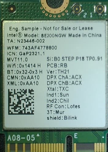
PD9BE200NG
Sep 13, 2023Intel BE200
Equipment Class
6CD - 15E 6 GHz Low Power Dual Client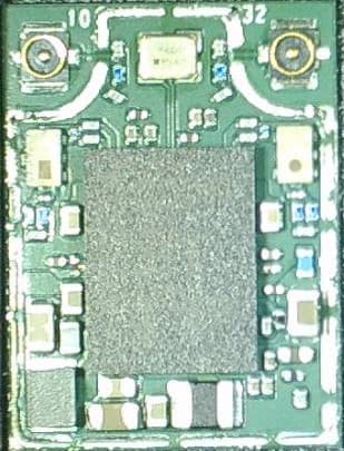
PD9BE200D2
Sep 13, 2023Intel BE200
Equipment Class
6CD - 15E 6 GHz Low Power Dual Client