PD9AX210NGIntel WiFi 6E AX210 Module
Intel Corporation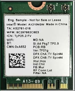
Click to zoom
Application Details
- Equipment Class
- 6XD - 15E 6 GHz Low Power Indoor Client
- Date of Grant
- Feb 17, 2021
- Application Purpose
- Original Equipment
- Date of Application
- Nov 10, 2020
- Equipment Note
- Intel WiFi 6E AX210 Module
- Frequency Range
- 6025.00000000 - 6985.00000000
- Company
- Intel Corporation
- Country
- France
Documents & Files
Document Text
Text extracted from the exhibit documents filed with the FCC. Open a document above to read the original.
Users Manual
Intel® WiFi Adapter Information Guide This version of Intel® PROSet/Wireless WiFi Software is compatible with the adapters listed below. Note that newer features provided in this software are generally not supported on older generations of wireless adapters. The following adapters are supported in Windows* 10: Intel® Wi-Fi 6E AX211 Intel® Wi-Fi 6E AX210 Intel® Wi-Fi 6 AX203 Intel® Wi-Fi 6 AX201 Intel® Wi-Fi 6 AX200 Intel® Wi-Fi 6 AX101 I With your WiFi network card, you can access WiFi networks, share files or printers, or even share your Internet connection. All these features can be explored using a WiFi network in your home or office. This WiFi network solution is designed for both home and business use. Additional users and features can be added as your networking needs grow and change. This guide contains basic information about Intel adapters. Intel® wireless adapters enable fast connectivity without wires for desktop and notebook PCs. Depending on the model of your Intel WiFi adapter, your adapter is compatible with 802.11a, 802.11b, 802.11g, 802.11n, 802.11ac and 802.11ax wireless standards. Operating at 2.4GHz, 5GHz or 6GHz frequency, you can now connect your computer to existing high-speed networks that use multiple access points within large or small environments. Your WiFi adapter maintains automatic data rate control according to the access point location and signal strength to achieve the fastest possible connection. Information in this document is subject to change without notice. Intel Corporation assumes no responsibility for errors or omissions in this document. Nor does Intel make any commitment to update the information contained herein. IMPORTANT NOTICE FOR ALL USERS OR DISTRIBUTORS: Intel wireless LAN adapters are engineered, manufactured, tested, and quality checked to ensure that they meet all necessary local and governmental regulatory agency requirements for the regions that they are designated and/or marked to ship into. Because wireless LANs are generally unlicensed devices that share spectrum with radars, satellites, and other licensed and unlicensed devices, it is sometimes necessary to dynamically detect, avoid, and limit usage to avoid interference with these devices. In many instances Intel is required to provide test data to prove regional and local compliance to regional and governmental regulations before certification or approval to use the product is granted. Intel's wireless LAN's EEPROM, firmware, and software driver are designed to carefully control parameters that affect radio operation and to ensure electromagnetic compliance (EMC). These parameters include, without limitation, RF power, spectrum usage, channel scanning, and human exposure. For these reasons Intel cannot permit any manipulation by third parties of the software provided in binary format with the wireless LAN adapters (e.g., the EEPROM and firmware). Furthermore, if you use any patches, utilities, or code with the Intel wireless LAN adapters that have been manipulated by an unauthorized party (i.e., patches, utilities, or code (including open source code modifications) which have not been validated by Intel), (i) you will be solely responsible for ensuring the regulatory compliance of the products, (ii) Intel will bear no liability, under any theory of liability for any issues associated with the modified products, including without limitation, claims under the warranty and/or issues arising from regulatory non-compliance, and (iii) Intel will not provide or be required to assist in providing support to any third parties for such modified products. Intel and the Intel logo are trademarks of Intel Corporation in the U.S. and/or other countries. *Other names and brands may be claimed as the property of others. © Intel Corporation. Regulatory Information This section provides regulatory information for the following wireless adapters: Intel® Wi-Fi 6 AX200 Intel® Wi-Fi 6 AX201 NOTE: Due to the evolving state of regulations and standards in the wireless LAN field (IEEE 802.11 and similar standards), the information provided herein is subject to change. Intel Corporation assumes no responsibility for errors or omissions in this document. Intel® Wi-Fi 6 AX203 Intel® Wi-Fi 6E AX210 Intel® Wi-Fi 6E AX211 NOTE: In this section, all references to the "wireless adapter" refer to all adapters listed above. The following information is provided: Information for the User Regulatory Information Regulatory ID Information for OEMs and Host Integrators INFORMATION FOR THE USER USA FCC Radio Frequency Exposure The FCC with its action in ET Docket 96-8 has adopted a safety standard for human exposure to radio frequency (RF) electromagnetic energy emitted by FCC certified equipment. The wireless adapter meets the Human Exposure requirements found in FCC Part 2, 15C, 15E along with guidance from KDB 447498, KDB 248227 and KDB 616217. Proper operation of this radio according to the instructions found in this manual will result in exposure substantially below the FCC’s recommended limits. The following safety precautions should be observed: - Do not touch or move antenna while the unit is transmitting or receiving. - Do not hold any component containing the radio such that the antenna is very close or touching any exposed parts of the body, especially the face or eyes, while transmitting. - Do not operate the radio or attempt to transmit data unless the antenna is connected; this behavior may cause damage to the radio. - Use in specific environments: Explosive Device Proximity Warning Warning: Do not operate a portable transmitter (including this wireless adapter) near unshielded blasting caps or in an explosive environment unless the transmitter has been modified to be qualified for such use Warning: The wireless adapter is not designed for use with high-gain directional antennas. Use On Aircraft Caution Caution: Regulations of commercial airline operators may prohibit airborne operation of certain elect…
Text truncated - open the document above for the full version.
Attestation Statements
100 Center Point Circle Columbia, SC 29210 Jan 10, 2020 Attestation Letter for Low Power Indoor Client Module Approval FCC ID: PD9AX210NG We, Intel Corporation, attest that this device under FCC ID PD9AX210NG complies with device protocol requirements and operational restrictions: for indoor client 6XD. a. Contention-Based Protocol, as demonstrated in the test report, is permanently embedded in the module and is not host-dependent. b. The device will only associate and connect with a low-power indoor access point or subordinate device and never directly connect to other client devices. c. This device will always initiate transmission under the control of a low-power indoor AP or subordinate except for brief transmissions before joining a network. These short messages will only occur if the client has detected an indoor AP or subordinate operating on a channel. These brief messages will have a time-out mechanism such that if it does not receive a response from an AP it will not continually repeat the request. d. Transmissions will be lower or equal to the power advertised by the indoor low-power access point or subordinate and never above the maximum output power allowed by the FCC grant for equipment class 6XD. e. Contention-based protocol as demonstrated in the test report is permanently embedded in the module and is not host-dependent. Furthermore, we fully understand this device is prohibited for control of or communications with unmanned aircraft systems, including drones. For any questions please contact me at your c onvenience. Steven C. Hackett Regul atory Technical Program Manager Wireless Test Certification Center [email protected]
Cover Letter(s)
100 Center Point Circle Columbia, SC 29210 September 30, 2020 Subject: Confidentiality Request for FCC ID: PD9AX210NG Pursuant to FCC 47 CRF 0.457(d) and 0.459 the applicant requests that a part of the subject FCC application be held confidential. Type of Confidentiality Requested Short Term Permanent Short Term Short Term Permanent Short Term Permanent Short Term Permanent Short Term Permanent Short Term Permanent Short Term Permanent Short Term Short Term Permanent Exhibit Block Diagrams External Photos Internal Photos Operation Description/Antenna Specificatio n Operation Description/HW Theory of Operation Operational Description Schematics Test Setu p Photos User’s Manual Intel Mobile Communications has spent substantial effort in developing this product and it is one of the first of its kind in industry. Having the subject information easily available to "competition" would negate the advantage they have achieved by developing this product. Not protecting the details of the design will result in financial hardship. Permanent Confidentiality: The applicant requests the exhibits listed above as permanently confidential be permanently withheld from public review due to materials that contain trade secrets and proprietary information not customarily released to the public. Short-Term Confidentiality: The applicant requests the exhibits selected above as short term confidential be withheld from public view for a period of 180 days from the date of the Grant of Equipment Authorization and prior to marketing. This is to avoid premature release of sensitive information prior to marketing or release of the product to the public. Applicant is also aware that they are responsible to notify ACB in the event information regarding the product or the product is made available to the public. ACB will then release the documents listed above for public disclosure pursuant to FCC Public Notice DA 04-1705. Sincerely, Steven C. Hackett By: __________________________ ________________________ (Signature/Title 1 ) (Print Name)
Cover Letter(s)
053019-02a Request for Modular/Limited Modular Approval ☐- Limited Split Modular Approval ☒- Modular Approval☐- Split Modular Approval Confidentiality Request for: ______PD9AX210NG______ 8 Basic Requirements – FCC Part 15.212(a)(1) For Items Marked “NO(*)”, the Limited Module Description Must be Filled Out on the Following Pages Modular Approval Requirement Requirement Met 1. The modular transmitter must have its own RF shielding. This is intended to ensure that the module does not have to rely upon the shielding provided by the device into which it is installed in order for all modular transmitter emissions to comply with FCC limits. It is also intended to prevent coupling between the RF circuitry of the module and any wires or circuits in the device into which the module is installed. Such coupling may result in non-compliant operation. The physical crystal and tuning capacitors may be located external to the shielded radio elements. 15.212(a)(1)(i) ☒ - YES ☐ - NO(*) Details: – The module contains a me tal shield which covers all RF components and circuitry. The shield is located on the top of the board next to antenna connector. See photo provided with this filing. 2. The modular transmitter must have buffered modulation/data inputs (if such inputs are provided) to ensure that the module will comply with FCC requirements under conditions of excessive data rates or over-modulation. 15.212(a)(1)(ii) ☒ - YES ☐ - NO(*) Details: – Data to the modulation circuit is buffered as described in the operational description provided with the application> 3. The modular transmitter must have its own power supply regulation on the module. This is intended to ensure that the module will comply with FCC requirements regardless of the design of the power supplying circuitry in the device into which the module is installed. 15.212(a)(1)(iii) ☒ - YES ☐- NO(*) Details: – The module contains its own power supply regulation. Please refer to operational description filed with this application 4. The modular transmitter must comply with the antenna and transmission system requirements of §§ 15.203, 15.204(b), 15.204(c), 15.212(a), and 2.929(b). The antenna must either be permanently attached or employ a ‘‘unique’’ antenna coupler (at all connections between the module and the antenna, including the cable). The ‘‘professional installation’’ provision of § 15.203 is not applicable to modules but can apply to limited modular approvals under paragraph 15.212(b). 15.212(a)(1)(iv) ☒ - YES ☐ - NO(*) Details: – The module c onnects to its antenna using an UFL connector which is considered a non-standard connector. The antenna and connector specification are provided with this filing. 5. The modular transmitter must be tested in a stand-alone configuration, i.e., the module must not be inside another device during testing. This is intended to demonstrate that the module is capable of complying with Part 15 emission limits regardless of the device into which it is eventually installed. Unless the transmitter module will be battery powered, it must comply with the AC line conducted requirements found in Section 15.207. AC or DC power lines and data input/output lines connected to the module must not contain ferrites, unless they will be marketed with the module (see Section 15.27(a)). The length of these lines shall be length typical of actual use or, if that length is unknown, at least 10 centimeters to insure that there is no coupling between the case of the module and supporting equipment. Any accessories, peripherals, or support equipment connected to the module during testing shall be unmodified or commercially available (see Section 15.31(i)). 15.212(a)(1)(v) ☐ - YES Details: – The module was tested in OEM host PC and is limited to installati on in the host described in this filing. September 30, 2020 Subject: Manufacturer’s Declaration for X - NO(*) ☐- Limited Modular Approval 053019-02a Modular Approval Requirement Requirement Met 6. The modular transmitter must be labeled with its own FCC ID number, or use an electron display (see KDB Publication 784748). If using a permanently affixed label with its own FCC ID number, if the FCC ID is not visible when the module is installed inside another device, then the outside of the device into which the module is installed must also display a label referring to the enclosed module. This exterior label can use wording such as the following: “Contains Transmitter Module FCC ID: XYZMODEL1” or “Contains FCC ID: XYZMODEL1.” Any similar wording that expresses the same meaning may be used. The Grantee may either provide such a label, an example of which must be included in the application for equipment authorization, or, must provide adequate instructions along with the module which explain this requirement. In the latter case, a copy of these instructions must be included in the application for equipment authorization. If the modular transmitter uses an electronic display of the FCC identification number, the information must be readily accessible and visible on the modular transmitter or on the device in which it is installed. If the module is installed inside another device, then the outside of the device into which the module is installed must display a label referring to the enclosed module. This exterior label can use wording such as the following: “Contains FCC certified transmitter module(s).” Any similar wording that expresses the same meaning may be used. The user manual must include instructions on how to access the electronic display. A copy of these instructions must be included in the application for equipment authorization. 15.212(a)(1)(vi) ☒ - YES ☐ - NO(*) Details: – There is a label on the module as shown in the labeling exhibit filed with this application. Host specific labeling instructions are shown in the installation manual .filed with this application. 7. The modular transmitter must comply with all specific rule or operating requirements applicable to t…
Text truncated - open the document above for the full version.
External Photos
AX210NGW External Photos
ID Label/Location Info
AX210NGW Label Location FCC ID: PD9AX210NG
Internal Photos
AX210NGW Internal Photo
RF Exposure Info
Test Report N° 200611-03.TR40 Rev. 02 56 of 62 Annex F. Calibration Certificates ID Device Type/Model Serial Number Manufacturer Calibration Certificate 0654 E-field Probe EUmmWV2 9366 SPEAG 0648 Dosimetric E-field Probe EX3DV4 7465 SPEAG 1062 6500MHz System Validation Dipole D6.5GHzV2 1013 SPEAG
RF Exposure Info
Intel Corporation S.A.S – WRF Lab 425 rue de Goa – Le Cargo B6 - 06600 Antibes, France Tel. +33493001400 / Fax +33493001401 Reference: WRF-DCS-TF-019 Version: 002 Application Date: 09/04/2020 1 of 60 TEST REPORT EUT Description WLAN and BT, 2x2 PCIe M.2 2230 adapter card Brand Name Intel® Wi-Fi 6E AX210 Model Name AX210NGW FCC/IC ID FCC ID: PD9AX210NG ; IC ID: 1000M-AX210NG Date of Test Start/End 2020-08-28 / 2020-12-28 Features 802.11ax, Dual Band, 2x2 Wi-Fi + Bluetooth® 5.2 (see section 5) Description Platform: Engineering sample + PIFA antenna Applicant Intel Mobile Communications Address 100 Center Point Circle, Suite 200 / Columbia, SC 29210 / United States Contact Person Steven Hackett Telephone/Fax/ Email [email protected] Reference Standards FCC 47 CFR Part §2.1093 (see section 1) RF Exposure Environment Portable devices - General population/uncontrolled exposure Testing Result Limit Maximum Power Density Result & Limit 4.23 W/m 2 (4cm 2 ) 10 W/m 2 (4cm 2 ) Maximum SAR Result & Limit 0.29 W/kg (1g) 1.6 W/kg (1g) Min. test separation distance 13mm Test Report identification 200611-03.TR40 Revision Control Rev. 04 This test report revision replaces any previous test report revision (see section 8) The test results relate only to the samples tested. This report shall not be reproduced, except in full, without the written approval of the laboratory. Reference to accreditation shall be used only by full reproduction of test report. Issued by Reviewed by Vaso KACULINI (Test Engineer Lead) Walid EL HAJJ (Scientist Officer) Test Report N° 200611-03.TR40 Rev. 04 2 of 60 Table of Contents 1. Standards, reference documents and applicable test methods ......................................................................... 4 2. General conditions, competences and guarantees ............................................................................................. 4 3. Environmental Conditions ...................................................................................................................................... 4 4. Test samples ............................................................................................................................................................ 4 5. EUT Features ............................................................................................................................................................ 5 6. Remarks and comments ......................................................................................................................................... 7 7. Test Verdicts summary ........................................................................................................................................... 7 8. Document Revision History .................................................................................................................................... 7 Annex A. PD Test & System Description ................................................................................................................. 8 POWER DENSITY DEFINITION ................................................................................................................................. 8 SPEAG FREE SPACE MEASUREMENT SYSTEM ....................................................................................................... 8 A.2.1 Measurement Setup .................................................................................................................................................... 8 A.2.2 E-Field Measurement Probe ........................................................................................................................................ 9 A.2.3 Worst Case Linearization Error .................................................................................................................................. 10 A.2.4 Data Evaluation ......................................................................................................................................................... 10 SYSTEM CHECK .................................................................................................................................................. 11 TEST EQUIPMENT LIST ........................................................................................................................................ 12 MEASUREMENT UNCERTAINTY EVALUATION ......................................................................................................... 13 RF EXPOSURE LIMITS ......................................................................................................................................... 14 Annex B. SAR Test & System Description ............................................................................................................ 15 SAR DEFINITION ................................................................................................................................................. 15 SPEAG SAR MEASUREMENT SYSTEM ................................................................................................................ 16 B.2.1 SAR Measurement Setup .......................................................................................................................................... 16 B.2.2 E-Field Measurement Probe ...................................................................................................................................... 17 B.2.3 SAM Phantom ........................................................................................................................................................... 17 B.2.4 Flat Phantom ............................................................................................................................................................. 18 B.2.5 Device Positioner ..............................................................................................................................…
Text truncated - open the document above for the full version.
Test Report
Intel Corporation S.A.S – WRF Lab 425 rue de Goa – Le Cargo B6 - 06600, Antibes, France Tel. +33493001400 / Fax +33493001401 Reference: WRF-DCS-TF-059 Version: 001 Application Date: 07/30/2020 1 of 57 TEST REPORT EUT Description WLAN and BT, 2x2 PCIe M.2 2230 adapter card Brand Name Intel® Wi-Fi 6E AX210 Model Name AX210NGW FCC ID PD9AX210NG Date of Test Start/End 2020-07-28 /2020-08-13 Features 802.11ax, Dual Band, 2x2 Wi-Fi 6 + Bluetooth® 5.2 (see section 5) Applicant Intel Mobile Communications Address 100 Center Point Circle, Suite 200 Columbia, South Carolina 29210 USA Contact Person Steven Hackett Telephone/Fax/ Email [email protected] Reference Standards FCC CFR Title 47 Part 15 E (see section 1) Test Report identification 200611-03.TR39 Revision Control Rev. 01 This test report revision replaces any previous test report revision (see section 8) The test results relate only to the samples tested. This report shall not be reproduced, except in full, without the written approval of the laboratory. Reference to accreditation shall be used only by full reproduction of test report. Issued by Reviewed by Ines KHARRAT (Test Engineer Lead) Cheiel IN (Technical Manager) Test Report N° 200611-03.TR39 Rev. 01 2 of 57 Table of Contents 1. Standards, reference documents and applicable test methods ......................................................................... 3 2. General conditions, competences and guarantees ............................................................................................. 3 3. Environmental Conditions ...................................................................................................................................... 3 4. Test samples ............................................................................................................................................................ 4 5. EUT Features ............................................................................................................................................................ 5 6. Remarks and comments ......................................................................................................................................... 5 7. Test Verdicts summary ........................................................................................................................................... 5 7.1. 802.11 A/N/AC/AX – U-NII- 5 TO U-NII-8 ................................................................................................................ 5 8. Document Revision History .................................................................................................................................... 5 Annex A. Test & System Description ....................................................................................................................... 6 A.1 MEASUREMENT SYSTEM ........................................................................................................................................ 6 A.2 TEST EQUIPMENT LIST .......................................................................................................................................... 8 A.3 MEASUREMENT UNCERTAINTY EVALUATION ........................................................................................................... 9 Annex B. Test Results UNII-5 to UNII-8 .................................................................................................................. 10 B.1 TEST CONDITIONS ............................................................................................................................................... 10 B.2 RADIATED SPURIOUS EMISSION ............................................................................................................................ 12 Annex C. Photographs ............................................................................................................................................ 52 C.1 TEST SETUP ....................................................................................................................................................... 52 C.2 TEST SAMPLE ..................................................................................................................................................... 53 Test Report N° 200611-03.TR39 Rev. 01 3 of 57 1. Standards, reference documents and applicable test methods FCC 1. FCC Title 47 CFR part 15 – Subpart E – Unlicensed National Information Infrastructure Devices. 2019-10-01 Edition 2. FCC Title 47 eCFR part 15 – Subpart E - Unlicensed National Information Infrastructure Devices. 2020-07-30 Online edition 3. FCC Title 47 CFR part 15 – Subpart C – §15.209 Radiated emission limits; general requirements. 2019-10-01 Edition 4. FCC OET KDB draft 987594 D02 EMC Measurement - U-NII 6 GHz devices operating in the 5.925-7.125 GHz band, August 14, 2020 5. FCC OET KDB 789033 D02 v02r01 - General U-NII Test Procedures New Rules – Guidelines for compliance testing of Unlicensed National Information Infrastructure (U-NII) Devices (Part 15, Subpart E) 6. ANSI C63.10-2013 American National Standard of Procedures for Compliance Testing of Unlicensed Wireless Devices. 2. General conditions, competences and guarantees ✓ Intel Corporation SAS Wireless RF Lab (Intel WRF Lab) is an Accredited Test Firm recognized by the FCC, with Designation Number FR0011. ✓ Intel WRF Lab declines any responsibility with respect to the identified information provided by the customer and that may affect the validity of results. ✓ Intel WRF Lab only provides testing services and is committed to providing reliable, unbiased test results and interpretations. ✓ Intel WRF Lab is liable to the client for the maintenance of the confidentiality of all information related to the item under test and the results of the test. ✓ Intel WRF Lab has developed calibration and proficiency programs for its measurement equipment to ensure correlated an…
Text truncated - open the document above for the full version.
Test Report
ACB comments Intel answers 1)The test data does now shows both peak and average measurements. From our analysis of the plots, it appears the antenna gain is factored into the offset. Therefore the limit is still -27 dBm/MHz for SISO modes. The plots show that the data is taking using 100 kHz, but then use a Band Power Function that we assume integrates from the 100 kHz to 1 MHz RBW requirement. The concern is that much of the peak data appears to exceed the -27 dBm. Please see plots placed into a separate file showing the results of concern. Please review. As per KDB 987594 addendum, the -27dBm/MHz is for average limit which lead to -7dBm/MHz (-27dBm/MHz + 20dB) for peak limit. • RMS Limit = -27dBm/MHz • Peak Limit = -7dBm/MHz All OOBE peak detector results are below the -7dBm/MHz peak limit 2)The same concern exists for some of the MIMO results, with the addition that it is uncertain where the 3 dB for the 2 antennas is factored into the data. Many labs would possibly adjust the offset from 5.6 to 8.6 for the 3 dB. However off hand it does not appear where this correction is taking place. Even with the correction – there does appear to be some plots exceeding the requirement as well. A clarification is described in the test report section B.2.5, see below. In our case instead of considering the 3dB correction in the offset of the spectrum analyzer they were applied to Peak and RMS limits: • MIMO RMS Limit for individual output= -30dBm/MHz • MIMO Peak Limit for individual output= -10dBm/MHz
Test Report
Reference: WRF-DCS-TF-059 Version: 001 Application Date: 07/30/2020 1 of TEST REPORT EUT Description WLAN and BT, 2x2 PCIe M.2 2230 adapter card Brand Name Intel® Wi-Fi 6E AX210 Model Name AX210NGW FCC ID PD9AX210NG Date of Test Start/End 2020-12-08 / 2020-12-11 Features 802.11ax, Dual Band, 2x2 Wi-Fi 6 + Bluetooth® 5.2 (see section 5) Applicant Intel Mobile Communications Add…
Text truncated - open the document above for the full version.
Contact Information
Applicant
Benjamin Lavenant(Regulatory Engineer)
Technical Contact
Intel CorporationSteven Hackett
[email protected]8033156704
100 Center Point Circle · Columbia · United States
Test Firm
Intel Corporation S.A.S.Nawfal ASRIH
[email protected]003349300962
Technical Specifications
| # | Rule Parts | Frequency Range | Power Output |
|---|---|---|---|
| 4 | 15E | 6.03 GHz - 6.99 GHz | 26.00 mW |
Other Applications from Intel Corporation
PD9BE201D2P
Aug 20, 2024Intel BE201D2WP
Equipment Class
NII - Unlicensed National Information Infrastructure TXPD9AX411NG
Jul 02, 2024Intel WiFi 6E AX411
Equipment Class
6CD - 15E 6 GHz Low Power Dual ClientPD9AX211D2H
Jan 28, 2024Intel Wi-Fi 6E AX211
Equipment Class
DSS - Part 15 Spread Spectrum Transmitter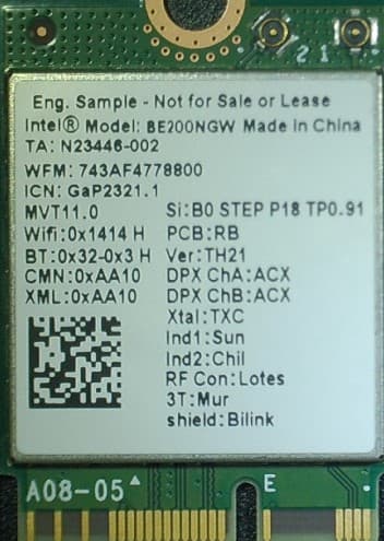
PD9BE200NG
Sep 13, 2023Intel BE200
Equipment Class
6CD - 15E 6 GHz Low Power Dual Client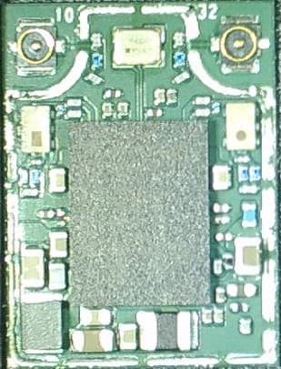
PD9BE200D2
Sep 13, 2023Intel BE200
Equipment Class
6CD - 15E 6 GHz Low Power Dual Client