PD9WM3965ABG802.11 a/b/g PCI Express Card
Intel Corporation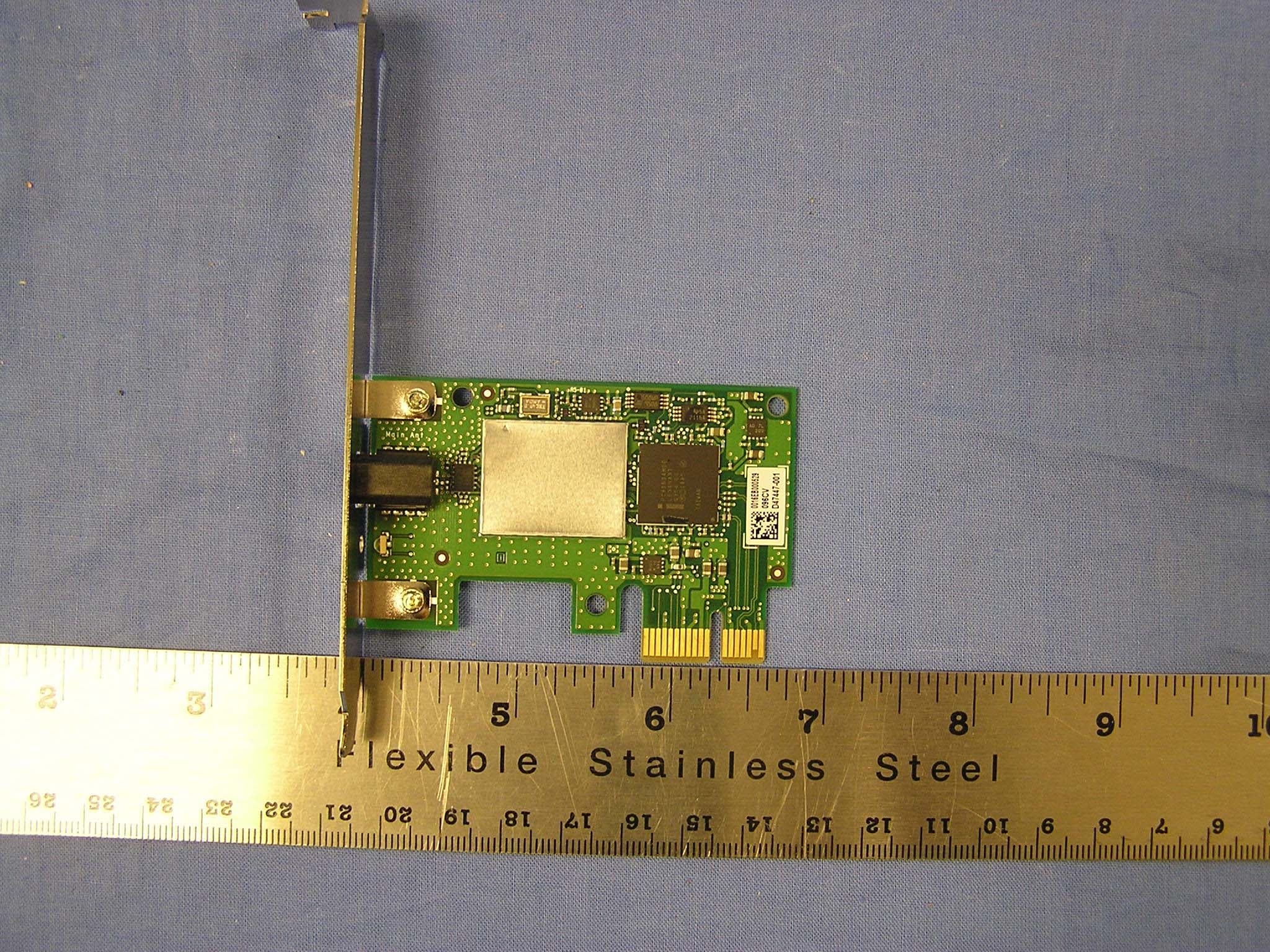
Click to zoom
Application Details
- Equipment Class
- NII - Unlicensed National Information Infrastructure TX
- Date of Grant
- Apr 26, 2006
- Application Purpose
- Original Equipment
- Date of Application
- Apr 25, 2006
- Equipment Note
- 802.11 a/b/g PCI Express Card
- Frequency Range
- 5260.00000000 - 5320.00000000
- Company
- Intel Corporation
- Country
- France
Documents & Files
Document Text
Text extracted from the exhibit documents filed with the FCC. Open a document above to read the original.
Users Manual
Back to Contents Regulatory Information: Intel(R) PRO/Wireless 3965ABG Network Connection User Guide Intel(R) PRO/Wireless 3965ABG Network Connection Intel(R) PRO/Wireless 3945ABG Network Connection Intel(R) PRO/Wireless 3945BG Network Connection Intel(R) PRO/Wireless 2915ABG Network Connection Intel(R) PRO/Wireless 2200BG Network Connection Intel(R) PRO/Wireless 3965ABG Network Connection Intel(R) PRO/Wireless 3945ABG Network Connection Intel(R) PRO/Wireless 3945BG Network Connection • Information for the User • Regulatory Information Intel(R) PRO/Wireless 2915ABG Network Connection • Information for the User • Regulatory Information Intel(R) PRO/Wireless 2200BG Network Connection • Information for the User • Regulatory Information Intel(R) PRO/Wireless 3965ABG Network Connection, Intel(R) PRO/Wireless 3945ABG Network Connection and the Intel(R) PRO/Wireless 3945BG Network Connection The information in this document applies to the following products: Tri-mode wireless LAN adapters (802.11a/802.11b/802.11g ) Intel(R) PRO/Wireless 3965ABG Network Connection (model WM3965ABG) Intel(R) PRO/Wireless 3945ABG Network Connection (model WM3945ABG) Dual-mode wireless LAN adapters (802.11b/802.11g ) Intel(R) PRO/Wireless 3945BG Network Connection (model WM3945BG) NOTE: Due to the evolving state of regulations and standards in the wireless LAN field (IEEE 802.11 and similar standards), the information provided herein is subject to change. Intel Corporation assumes no responsibility for errors or omissions in this document. Nor does Intel make any commitment to update the information contained herein. Information for the user Safety Notices The FCC with its action in ET Docket 96-8 has adopted a safety standard for human exposure to radio frequency (RF) electromagnetic energy emitted by FCC certified equipment. The Intel(R) PRO/Wireless 3965ABG Network Connection adapter, Intel(R) PRO/Wireless 3945ABG Network Connection adapter, or the Intel(R) PRO/Wireless 3945BG Network Connection adapter meet the Human Exposure limits found in OET Bulletin 65, supplement C, 2001, and ANSI/IEEE C95.1, 1992. Proper operation of this radio according to the instructions found in this manual will result in exposure substantially below the FCC’s recommended limits. The following safety precautions should be observed: • Do not touch or move antenna while the unit is transmitting or receiving. • Do not hold any component containing the radio such that the antenna is very close or touching any exposed parts of the body, especially the face or eyes, while transmitting. • Do not operate the radio or attempt to transmit data unless the antenna is connected; if not, the radio may be damaged. • Use in specific environments: • The use of wireless devices in hazardous locations is limited by the constraints posed by the safety directors of such environments. • The use of wireless devices on airplanes is governed by the Federal Aviation Administration (FAA). • The use of wireless devices in hospitals is restricted to the limits set forth by each hospital. • Antenna use: • In order to comply with FCC RF exposure limits, low gain integrated antennas should be located at a minimum distance of 20 cm (8 inches) or more from the body of all persons. • High-gain, wall-mount, or mast-mount antennas are designed to be professionally installed and should be located at a minimum distance of 30 cm (12 inches) or more from the body of all persons. Please contact your professional installer, VAR, or antenna manufacturer for proper installation requirements. • Explosive Device Proximity Warning (see below) • Antenna Warning (see below) • Use on Aircraft Caution (see below) • Other Wireless Devices (see below) • Power Supply (Access Point) (see below) Explosive Device Proximity Warning Warning: Do not operate a portable transmitter (such as a wireless network device) near unshielded blasting caps or in an explosive environment unless the device has been modified to be qualified for such use. Antenna Warnings Warning: To comply with the FCC and ANSI C95.1 RF exposure limits, it is recommended for the Intel(R) PRO/Wireless 3965ABG Network Connection adapter, Intel(R) PRO/Wireless 3945ABG Network Connection adapter, or the Intel(R) PRO/Wireless 3945BG Network Connection adapter installed in a desktop or portable computer, that the antenna for this device be installed so as to provide a separation distance of al least 20 cm (8 inches) from all persons and that the antenna must not be co-located or operating in conjunction with any other antenna or radio transmitter. It is recommended that the user limit exposure time if the antenna is positioned closer than 20 cm (8 inches). Warning: Intel(R) PRO/Wireless LAN products are not designed for use with high-gain directional antennas. Use of such antennas with these products is illegal. Use On Aircraft Caution Caution: Regulations of the FCC and FAA prohibit airborne operation of radio- frequency wireless devices because their signals could interfere with critical aircraft instruments. Other Wireless Devices Safety Notices for Other Devices in the Wireless Network: Refer to the documentation supplied with wireless Ethernet adapters or other devices in the wireless network. Local Restrictions on 802.11a, 802.11b, and 802.11g Radio Usage Caution: Due to the fact that the frequencies used by 802.11a, 802.11b and 802.11g wireless LAN devices may not yet be harmonized in all countries, 802.11a, 802.11b, and 802.11g products are designed for use only in specific countries, and are not allowed to be operated in countries other than those of designated use. As a user of these products, you are responsible for ensuring that the products are used only in the countries for which they were intended and for verifying that they are configured with the correct selection of frequency and channel for the country of use. The device transmit power control (TPC) interface is part of the Intel(R) PROSet/Wireless software. Ope…
Text truncated - open the document above for the full version.
Cover Letter(s)
To: American TCB From: Claire Hoque Attn: Douglas E. Noble Date: Apr. 24, 2006 Re: Intel Corporation, FCC ID: PD9WM3965ABG Dear Douglas, Please see our answer below. 1.) Internal photos need to show the back of the board as well as the front. Please revise internal photos. <answer> please see revised internal photos uploaded to ATCB today. 2.) The external photos also need to show all side of the EUT and all connection ports. Please revise external photos. <answer> please see revised external photos uploaded to ATCB today. 3.) MPE needs to show the antenna numerical gain and the mW power ouput. I have enclosed an attachment showing how this should be presented. You do not have to use this formula although it is the easiest. I do however recommend The table to look like the attachment showing the same fields. MPE has to be calculated to 20 cm distance. 802.11g with a power of 0.306 and a numerical antenna gain of 1.16 at a distance of 20 cm would be .070 mW/cm2. Please revise MPE exhibit. Please see attachment. <answer>The formulas in the MPE exhibit are derived so as to provide a direct calculation of the Power Density S in mW/cm^2 as a function of the power in dBm and the antenna gain in dBi; this formula will yield the same results as the formulas that you presented in the sample format. The Power Density was calculated at a 20 cm distance. The power originally entered in the table was the wrong number and this typographical error has been corrected in the attached updated reports. 4.) I am also including some new guidelines from the FCC on testing DTS. <answer> Thanks. 5.) Please upload antenna exhibit with information concerning the antenna used in this filing. <answer> the antenna exhibit was already uploaded to ATCB on 4/17. As addressed in the reports, the radio utilizes external WLAN self standing dual band vertically polarized antenna with a 1.5m cable and a stripline connector, the maximum gain is 0.64 dBi in the 2.4 GHz band and –2.05 in the 5.725 GHz band. FCC, VCCI, CISPR, CE, ACA, NZ 561F MONTEREY ROAD, MORGAN HILL, CA 95037-9001 UL, CSA, TUV, BSMI, DHHS, NVLAP PHONE: (408) 463-0885 FAX: (408) 463-0888 www.ccsemc.com 6.) The band edge plots should also show the same plot with the resolution bandwidth lowered to 10 Hz. The plots you have in spurious emission that are at 10Hz RBW should be included with the band edge plots. <answer>Please clarify the question and indicate exactly which plots are in error. We have reviewed the report and believe it is correct: the conducted spurious measurements were made with an RBW = 100 kHz, VBW > 100 kHz; the radiated bandedge measurements were made with RBW = VBW = 1 MHz for peak measurements and RBW = 1 MHz, VBW = 10 Hz for average measurements. Thanks, Claire Hoque Compliance Certification Services 561 F Monterey Rd. Morgan Hill, CA 95037 Phone: 408-463-0885 ext 123 Fax: 408-463-0888
ID Label/Location Info
PROPOSED FCC ID LABEL AND LOCATION INTEL CORPORATION This device complies with Part 15 of the FCC Rules. Operation is subject to the following two conditions: (1) this device may not cause harmful interference, and (2) this device must accept any interference received, including interference that may cause undesired operation. FCC ID: PD9WM3965ABG FCC ID LABEL LOCATION PROPOSED FCC ID LABEL FOR HOST DEVICE INTEL CORPORATION This device contains FCC ID: PD9WM3965ABG FCC ID and IC Label format Applicant : Intel Corporation FCC ID: PD9WM3965ABG IC Certification Number: 1000M-3965ABG Model No: WM3965ABG WM3965ABG FCC ID: PD9WM3965ABG IC: 1000M-3965ABG Intel Corporation
RF Exposure Info
REPORT NO: 06U10130-1C DATE: APRIL 24, 2006 EUT: 802.11a/b/g PCI EXPRESS CARD FCC ID: PD9WM3965ABG Page 33 of 119 COMPLIANCE CERTIFICATION SERVICES DOCUMENT NO: CCSUP4031A 561F MONTEREY ROAD, MORGAN HILL, CA 95037 USA TEL: (408) 463-0885 FAX: (408) 463-0888 This report shall not be reproduced except in full, without the written approval of CCS. 7.1.4. MAXIMUM PERMISSIBLE EXPOSURE LIMITS §1.1310 The criteria listed in Table 1 shall be used to evaluate the environmental impact of human exposure to radio-frequency (RF) radiation as specified in §1.1307(b), except in the case of portable devices which shall be evaluated according to the provisions of §2.1093 of this chapter. REPORT NO: 06U10130-1C DATE: APRIL 24, 2006 EUT: 802.11a/b/g PCI EXPRESS CARD FCC ID: PD9WM3965ABG Page 34 of 119 COMPLIANCE CERTIFICATION SERVICES DOCUMENT NO: CCSUP4031A 561F MONTEREY ROAD, MORGAN HILL, CA 95037 USA TEL: (408) 463-0885 FAX: (408) 463-0888 This report shall not be reproduced except in full, without the written approval of CCS. CALCULATIONS Given E = √ (30 * P * G) / d and S = E ^ 2 / 3770 where E = Field Strength in Volts/meter P = Power in Watts G = Numeric antenna gain d = Distance in meters S = Power Density in milliwatts/square centimeter Combining equations and rearranging the terms to express the distance as a function of the remaining variables yields: d = √ ((30 * P * G) / (3770 * S)) Changing to units of Power to mW and Distance to cm, using: P (mW) = P (W) / 1000 and d (cm) =100 * d (m) yields d = 100 * √ ((30 * (P / 1000) * G) / (3770 * S)) d = 0.282 * √ (P * G / S) where d = distance in cm P = Power in mW G = Numeric antenna gain S = Power Density in mW/cm^2 Substituting the logarithmic form of power and gain using: P (mW) = 10 ^ (P (dBm) / 10) and G (numeric) = 10 ^ (G (dBi) / 10) yields d = 0.282 * 10 ^ ((P + G) / 20) / √ S where d = MPE distance in cm P = Power in dBm G = Antenna Gain in dBi S = Power Density Limit in mW/cm^2 Rearranging terms to calculate the power density at a specific distance yields S = 0.0795 * 10 ^ ((P + G) / 10) / (d^2) REPORT NO: 06U10130-1C DATE: APRIL 24, 2006 EUT: 802.11a/b/g PCI EXPRESS CARD FCC ID: PD9WM3965ABG Page 35 of 119 COMPLIANCE CERTIFICATION SERVICES DOCUMENT NO: CCSUP4031A 561F MONTEREY ROAD, MORGAN HILL, CA 95037 USA TEL: (408) 463-0885 FAX: (408) 463-0888 This report shall not be reproduced except in full, without the written approval of CCS. LIMITS From §1.1310 Table 1 (B), the maximum value of S = 1.0 mW/cm^2 RESULTS No non-compliance noted: (MPE distance equals 20 cm) NOTE: For mobile or fixed location transmitters, the minimum separation distance is 20 cm, even if calculations indicate that the MPE distance would be less. ModeMPEOutputAntennaPower DistancePowerGainDensity (cm)(dBm)(dBi)(mW/cm^2) 802.11b20.018.950.640.02 802.11g20.024.850.640.07 REPORT NO: 06U10130-1C DATE: APRIL 24, 2006 EUT: 802.11a/b/g PCI EXPRESS CARD FCC ID: PD9WM3965ABG Page 70 of 119 COMPLIANCE CERTIFICATION SERVICES DOCUMENT NO: CCSUP4031A 561F MONTEREY ROAD, MORGAN HILL, CA 95037 USA TEL: (408) 463-0885 FAX: (408) 463-0888 This report shall not be reproduced except in full, without the written approval of CCS. 7.2.4. MAXIMUM PERMISSIBLE EXPOSURE LIMITS §1.1310 The criteria listed in Table 1 shall be used to evaluate the environmental impact of human exposure to radio-frequency (RF) radiation as specified in §1.1307(b), except in the case of portable devices which shall be evaluated according to the provisions of §2.1093 of this chapter. REPORT NO: 06U10130-1C DATE: APRIL 24, 2006 EUT: 802.11a/b/g PCI EXPRESS CARD FCC ID: PD9WM3965ABG Page 71 of 119 COMPLIANCE CERTIFICATION SERVICES DOCUMENT NO: CCSUP4031A 561F MONTEREY ROAD, MORGAN HILL, CA 95037 USA TEL: (408) 463-0885 FAX: (408) 463-0888 This report shall not be reproduced except in full, without the written approval of CCS. CALCULATIONS Given E = √ (30 * P * G) / d and S = E ^ 2 / 3770 where E = Field Strength in Volts/meter P = Power in Watts G = Numeric antenna gain d = Distance in meters S = Power Density in milliwatts/square centimeter Combining equations and rearranging the terms to express the distance as a function of the remaining variables yields: d = √ ((30 * P * G) / (3770 * S)) Changing to units of Power to mW and Distance to cm, using: P (mW) = P (W) / 1000 and d (cm) =100 * d (m) yields d = 100 * √ ((30 * (P / 1000) * G) / (3770 * S)) d = 0.282 * √ (P * G / S) where d = distance in cm P = Power in mW G = Numeric antenna gain S = Power Density in mW/cm^2 Substituting the logarithmic form of power and gain using: P (mW) = 10 ^ (P (dBm) / 10) and G (numeric) = 10 ^ (G (dBi) / 10) yields d = 0.282 * 10 ^ ((P + G) / 20) / √ S where d = MPE distance in cm P = Power in dBm G = Antenna Gain in dBi S = Power Density Limit in mW/cm^2 Rearranging terms to calculate the power density at a specific distance yields S = 0.0795 * 10 ^ ((P + G) / 10) / (d^2) REPORT NO: 06U10130-1C DATE: APRIL 24, 2006 EUT: 802.11a/b/g PCI EXPRESS CARD FCC ID: PD9WM3965ABG Page 72 of 119 COMPLIANCE CERTIFICATION SERVICES DOCUMENT NO: CCSUP4031A 561F MONTEREY ROAD, MORGAN HILL, CA 95037 USA TEL: (408) 463-0885 FAX: (408) 463-0888 This report shall not be reproduced except in full, without the written approval of CCS. LIMITS From §1.1310 Table 1 (B), the maximum value of S = 1.0 mW/cm^2 RESULTS No non-compliance noted: (MPE distance equals 20 cm) NOTE: For mobile or fixed location transmitters, the minimum separation distance is 20 cm, even if calculations indicate that the MPE distance would be less. ModeMPEOutputAntennaPower DistancePowerGainDensity (cm)(dBm)(dBi)(mW/cm^2) 802.11a20.024.86-2.050.04 REPORT NO: 06U10130-2 DATE: APTIR 10,2006 EUT: 802.11a/b/g PCI EXPRESS CARD FCC ID: PD9WM3965ABG Page 19 of 19 COMPLIANCE CERTIFICATION SERVICES DOCUMENT NO: CCSUP4031A 561F MONTEREY ROAD, MORGAN HILL, CA 95037 USA TEL: (408) 463-0885 FAX: (408) 463-0888 This report shall not be reproduced except in full, without the written approval of CCS. …
Text truncated - open the document above for the full version.
RF Exposure Info
Size 140 mm x 64 mm dia. Weight 100 g Frequency Range (GHz) 2.39 – 2.5; 4.9 – 5.85 Gain at connector >-3 dBi @ 2.4 Ghz >-5 dBi @ 5 GHz Return Loss < -10 dB VSWR < 2.0:1 Operating Temperature -40°C to 70°C Polarization Vertical Power Handling 10 Watt Max. Feed Point Impedance 50 Ohms Technical Data Sheet External WLAN Antenna Tyco Electronics P/N: 1513534-1 Electrical Description • This is a self-standing dual band vertically polarized antenna with a 1.5m cable and a stripline connector • 802.11a/b/g coverage Mechanical © 2005 by Tyco Electronics Corporation. Tyco RangeStar and RangeStar W ireless are trademarks. Dimensions Tyco Sample #1 Az Gain
Test Report
FCC CFR47 PART 15 SUBPART C CERTIFICATION TEST REPORT FOR 802.11 a/b/g PCI EXPRESS CARD MODEL NUMBER: WM3965ABG FCC ID: PD9WM3965ABG REPORT NUMBER: 06U10130-2 ISSUE DATE: APRIL 10, 2006 Prepared for INTEL CORPORATION 2111 N.E.25 TH AVE. HILLSBORO, OR 97124, USA Prepared by COMPLIANCE CERTIFICATION SERVICES 561F MONTEREY ROAD MORGAN HILL, CA 95037, USA TEL: (408) 463-0885 FAX: (408) 463-0888 REPORT NO: 06U10130-2 DATE: APTIR 10,2006 EUT: 802.11a/b/g PCI EXPRESS CARD FCC ID: PD9WM3965ABG Page 2 of 2 COMPLIANCE CERTIFICATION SERVICES DOCUMENT NO: CCSUP4031A 561F MONTEREY ROAD, MORGAN HILL, CA 95037 USA TEL: (408) 463-0885 FAX: (408) 463-0888 This report shall not be reproduced except in full, without the written approval of CCS. Revision History Rev. Issue Date Revisions Revised By - 4/10/06 Initial Issue D.G. REPORT NO: 06U10130-2 DATE: APTIR 10,2006 EUT: 802.11a/b/g PCI EXPRESS CARD FCC ID: PD9WM3965ABG Page 3 of 3 COMPLIANCE CERTIFICATION SERVICES DOCUMENT NO: CCSUP4031A 561F MONTEREY ROAD, MORGAN HILL, CA 95037 USA TEL: (408) 463-0885 FAX: (408) 463-0888 This report shall not be reproduced except in full, without the written approval of CCS. TABLE OF CONTENTS 1. ATTESTATION OF TEST RESULTS............................................................................................. 4 2. TEST METHODOLOGY .................................................................................................................. 5 3. FACILITIES AND ACCREDITATION .......................................................................................... 5 4. CALIBRATION AND UNCERTAINTY.......................................................................................... 5 4.1. MEASURING INSTRUMENT CALIBRATION ............................................................................. 5 4.2. MEASUREMENT UNCERTAINTY ............................................................................................... 5 5. EQUIPMENT UNDER TEST............................................................................................................6 5.1. DESCRIPTION OF EUT ..............................................................................................................6 5.2. MAXIMUM OUTPUT POWER .................................................................................................... 6 5.3. DESCRIPTION OF AVAILABLE ANTENNAS ............................................................................. 6 5.4. SOFTWARE AND FIRMWARE .................................................................................................... 6 5.5. WORST-CASE CONFIGURATION AND MODE......................................................................... 6 5.6. DESCRIPTION OF TEST SETUP ................................................................................................ 7 6. TEST AND MEASUREMENT EQUIPMENT ................................................................................ 9 7. LIMITS AND RESULTS ................................................................................................................. 10 7.1. CHANNEL TESTS FOR THE 5150 TO 5350 MHz BAND ......................................................... 10 7.1.1. EMISSION BANDWIDTH ................................................................................................ 10 7.1.2. PEAK POWER ................................................................................................................... 14 7.1.3. MAXIMUM PERMISSIBLE EXPOSURE ........................................................................ 19 7.1.4. AVERAGE POWER........................................................................................................... 22 7.1.5. PEAK POWER SPECTRAL DENSITY ............................................................................ 23 7.1.6. PEAK EXCURSION .......................................................................................................... 28 7.1.7. CONDUCTED SPURIOUS EMISSIONS.......................................................................... 32 7.1.8. FREQUENCY STABILITY ............................................................................................... 36 7.2. RADIATED EMISSIONS.............................................................................................................39 7.2.1. TRANSMITTER RADIATED SPURIOUS EMISSIONS ................................................. 39 7.2.2. TRANSMITTER ABOVE 1 GHZ FOR 5150 TO 5350 MHz BAND ............................... 42 7.2.3. WORST-CASE RADIATED EMISSIONS BELOW 1 GHz ............................................. 51 7.3. POWERLINE CONDUCTED EMISSIONS ................................................................................ 55 8. SETUP PHOTOS .............................................................................................................................. 59 REPORT NO: 06U10130-2 DATE: APTIR 10,2006 EUT: 802.11a/b/g PCI EXPRESS CARD FCC ID: PD9WM3965ABG Page 4 of 4 COMPLIANCE CERTIFICATION SERVICES DOCUMENT NO: CCSUP4031A 561F MONTEREY ROAD, MORGAN HILL, CA 95037 USA TEL: (408) 463-0885 FAX: (408) 463-0888 This report shall not be reproduced except in full, without the written approval of CCS. 1. ATTESTATION OF TEST RESULTS COMPANY NAME: INTEL CORPORATION 2111 N.E. 25TH AVE. HILLSBORO, OR 97124, USA EUT DESCRIPTION: 802.11a/b/g PCI EXPRESS CARD MODEL: WM3965ABG SERIAL NUMBER: 000529096 DATE TESTED: MARCH 29 to APRIL 1, 2006 APPLICABLE STANDARDS STANDARD TEST RESULTS FCC PART 15 SUBPART C NO NON-COMPLIANCE NOTED Compliance Certification Services, Inc. tested the above equipment in accordance with the requirements set forth in the above standards. The test results show that the equipment tested is capable of demonstrating compliance with the requirements as documented in this report. Note: The results documented in this report apply only to the tested sample, under the conditions and modes of operation as described herein. This document may not be altered or revise…
Text truncated - open the document above for the full version.
Test Setup Photos
REPORT NO: 06U10130-2 DATE: APTIR 10,2006 EUT: 802.11a/b/g PCI EXPRESS CARD FCC ID: PD9WM3965ABG Page 59 of 59 COMPLIANCE CERTIFICATION SERVICES DOCUMENT NO: CCSUP4031A 561F MONTEREY ROAD, MORGAN HILL, CA 95037 USA TEL: (408) 463-0885 FAX: (408) 463-0888 This report shall not be reproduced except in full, without the written approval of CCS. 8. SETUP PHOTOS ANTENNA PORT CONDUCTED RF MEASUREMENT SETUP ANTENNA PORT CONDUCTED PHOTO REPORT NO: 06U10130-2 DATE: APTIR 10,2006 EUT: 802.11a/b/g PCI EXPRESS CARD FCC ID: PD9WM3965ABG Page 60 of 60 COMPLIANCE CERTIFICATION SERVICES DOCUMENT NO: CCSUP4031A 561F MONTEREY ROAD, MORGAN HILL, CA 95037 USA TEL: (408) 463-0885 FAX: (408) 463-0888 This report shall not be reproduced except in full, without the written approval of CCS. RADIATED RF MEASUREMENT SETUP RADIATED FRONT PHOTO REPORT NO: 06U10130-2 DATE: APTIR 10,2006 EUT: 802.11a/b/g PCI EXPRESS CARD FCC ID: PD9WM3965ABG Page 61 of 61 COMPLIANCE CERTIFICATION SERVICES DOCUMENT NO: CCSUP4031A 561F MONTEREY ROAD, MORGAN HILL, CA 95037 USA TEL: (408) 463-0885 FAX: (408) 463-0888 This report shall not be reproduced except in full, without the written approval of CCS. RADIATED BACK PHOTO REPORT NO: 06U10130-2 DATE: APTIR 10,2006 EUT: 802.11a/b/g PCI EXPRESS CARD FCC ID: PD9WM3965ABG Page 62 of 62 COMPLIANCE CERTIFICATION SERVICES DOCUMENT NO: CCSUP4031A 561F MONTEREY ROAD, MORGAN HILL, CA 95037 USA TEL: (408) 463-0885 FAX: (408) 463-0888 This report shall not be reproduced except in full, without the written approval of CCS. POWERLINE CONDUCTED EMISSIONS MEASUREMENT SETUP LINE CONDUCTED FRONT PHOTO REPORT NO: 06U10130-2 DATE: APTIR 10,2006 EUT: 802.11a/b/g PCI EXPRESS CARD FCC ID: PD9WM3965ABG Page 63 of 63 COMPLIANCE CERTIFICATION SERVICES DOCUMENT NO: CCSUP4031A 561F MONTEREY ROAD, MORGAN HILL, CA 95037 USA TEL: (408) 463-0885 FAX: (408) 463-0888 This report shall not be reproduced except in full, without the written approval of CCS. END OF REPORT LINE CONDUCTED BACK PHOTO
Contact Information
Applicant
Benjamin Lavenant(Regulatory Engineer)
Technical Contact
IntelRobert Paxman
[email protected]503-712-8077
2111 NE 25th AVe. · Hillsboro, Oregon · United States
Test Firm
Intel CorporationRobert Castro
Technical Specifications
| # | Rule Parts | Frequency Range | Power Output |
|---|---|---|---|
| 2 | 15E | 5.26 GHz - 5.32 GHz | 40.00 mW |
Other Applications from Intel Corporation
PD9BE201D2P
Aug 20, 2024Intel BE201D2WP
Equipment Class
NII - Unlicensed National Information Infrastructure TXPD9AX411NG
Jul 02, 2024Intel WiFi 6E AX411
Equipment Class
6CD - 15E 6 GHz Low Power Dual ClientPD9AX211D2H
Jan 28, 2024Intel Wi-Fi 6E AX211
Equipment Class
DSS - Part 15 Spread Spectrum Transmitter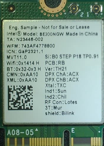
PD9BE200NG
Sep 13, 2023Intel BE200
Equipment Class
6CD - 15E 6 GHz Low Power Dual Client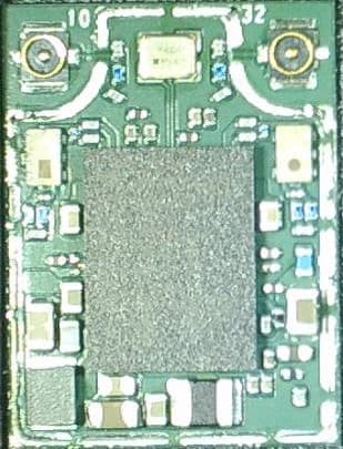
PD9BE200D2
Sep 13, 2023Intel BE200
Equipment Class
6CD - 15E 6 GHz Low Power Dual Client