PD9WM3B2100Mini-PCI Transmitter Card
Intel Corporation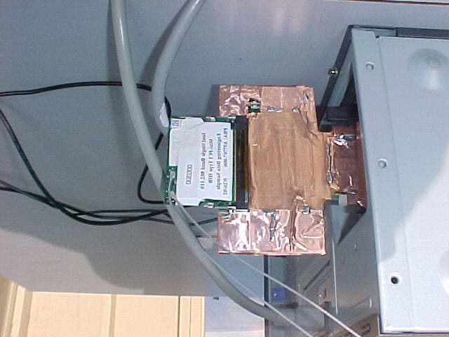
Click to zoom
Application Details
- Equipment Class
- DTS - Digital Transmission System
- Date of Grant
- Dec 19, 2002
- Application Purpose
- Original Equipment
- Date of Application
- Dec 19, 2002
- Equipment Note
- Mini-PCI Transmitter Card
- Frequency Range
- 2412.00000000 - 2462.00000000
- Company
- Intel Corporation
- Country
- France
Documents & Files
Document Text
Text extracted from the exhibit documents filed with the FCC. Open a document above to read the original.
Users Manual
Intel(R) PRO/Wireless LAN Mini PCI Adapter User's Guide This document provides information for the following wireless devices: l Intel(R) PRO/Wireless LAN 7100 3B Mini PCI Adapter, operating at 5 GHz l Intel(R) PRO/Wireless LAN 2100 3B Mini PCI Adapter, operating at 2.4 GHz These wireless adapters operate with high-capacity networks using multiple access points within large or small environments. Using the Intel(R) PROSet Windows utility you can configure, manage wireless local area network (WLAN) management tasks, adapter switching functions, and connections. Wireless LAN General Information About Wireless LAN Technology Administrator's Guide Adapter Setup and Configuration Software Installation Using PROSet Connecting to a Network Security Overview Setting Up Security Troubleshooting Specifications Glossary Support and Warranty Customer Support Software License Safety and Regulatory Notices Limited Warranty Adapter Registration Legal Notices Copyright © 2002 Intel Corporation. All rights reserved. Intel Corporation, 5200 N.E. Elam Young Parkway, Hillsboro, OR 97124-6497 Intel Corporation assumes no responsibility for errors or omissions in this document. Nor does Intel make any commitment to update the information contained herein. Intel, Itanium, and Pentium are trademarks or registered trademarks of Intel Corporation or its subsidiaries in the United States and other countries. *Other names and brands may be claimed as the property of others. Back to Contents Page About Wireless LAN Technology l Choosing a WLAN l Configuring a WLAN l Identifying a WLAN l Surveying the Site of Your WLAN l Factors Affecting Range l Stronger Security A wireless network connects computers without using network cables. Computers use radio communications to send data between each other. You can communicate directly with other wireless computers, or connect to an existing network through a wireless access point. When you set up your wireless adapter, you select the operating mode for the kind of wireless network you want. You can use your Intel(R) PRO/Wireless adapter to connect to other similar wireless devices that comply with the 802.11 standard for wireless networking. Choosing a Wireless LAN Mode Wireless LANs can operate with or without access points, depending on the number of users in the network. Infrastructure mode uses access points to allow wireless computers to send and receive information. Wireless computers transmit to the access point, the access point receives the information and rebroadcasts it to other computers. The access point can also connect to a wired network or to the Internet. Multiple access points can work together to provide coverage over a wide area. Peer-to-Peer mode, also called Ad Hoc mode, works without access points and allows wireless computers to send information directly to other wireless computers. You can use Peer-to-Peer mode to network computers in a home or small office or to set up a temporary wireless network for a meeting. Configuring a Wireless LAN There are three basic components that must be configured for a wireless LAN to operate properly: l Network Name—Each wireless network uses a unique Network Name to identify the network. This name is called the Service Set Identifier (SSID). When you set up your wireless adapter, you specify the SSID. If you want to connect to an existing network, you must use the name for that network. If you are setting up your own network you can make up your own name and use it on each computer. The name can be up to 32 characters long and contain letters and numbers. l Profiles—When you set up your computer to access a wireless network, Intel(R) PROSet creates a profile for the wireless settings that you specify. If you want to connect to another network, you can scan for existing networks and make a temporary connection, or create a new profile for that network. After you create profiles, your computer will automatically connect when you change locations. l Security—The 802.11 wireless networks use encryption to help protect your data. Wired equivalent privacy (WEP) uses a 64-bit or 128-bit shared encryption key to scramble data. Before a computer transmits data, it scrambles the data using the secret encryption key. The receiving computer uses this same key to unscramble the data. If you are connecting to an existing network, use the encryption key provided by the administrator of the wireless network. If you are setting up your own network you can make up your own key and use it on each computer. Identifying a Wireless Network Depending on the size and components of a wireless LAN, there are many ways to identify a wireless LAN: l The Network Name or Service Set Identifier (SSID)—Identifies a wireless network. All wireless devices on the network must use the same SSID. l Extended Service Set Identifier (ESSID)—A special case of SSID used to identify a wireless network that includes access points. l Independent Basic Service Set Identifier (IBSSID)—A special case of SSID used to identify a network of wireless computers configured to communicate directly with one another without using an access point. l Basic Service Set Identifier (BSSID)—A unique identifier for each wireless device. The BSSID is the Ethernet MAC address of the device. l Broadcast SSID—An access point can respond to computers sending probe packets with the broadcast SSID. If this feature is enabled on the access point, any wireless user can associate with the access point by using a blank (null) SSID. Surveying the Site of Your Wireless LAN Conducting a site survey for your wireless LAN is the most crucial step in the process of setting up a wireless network. It greatly reduces the amount of troubleshooting you will have to do once you have the wireless LAN set up and ready for connection testing. To conduct a site survey, you will need the following tools: l An access point (or laptop computer) that is set up to be the transmitter. It should be mounted near a…
Text truncated - open the document above for the full version.
Users Manual
Calexico Compliance Document Page 1 12/20/02 Mobile Communications Division Compliance Notices Source Document for OEMs Calexico Created: 09/25/02 Last Updated: 12/20/02TL Authors: Paul Straley, Tony Lukyn Calexico Compliance Document Page 2 12/20/02 Revision History Date Changes 09/25/02 Created document 10/03/02 Corrected errors in document, added 3 additional Mini PCI models, genericized product references to refer to “LAN Mini PCI Adapters” 10/08/02 Added Annex II under 1999/5/EC for 2.4 GHz products (PS) 12/18/02 Added “Information for the OEM” page 1 and additional text for OEM integrators page 4 (TL) 12/20/02 Added End Product Label: FCC ID “XXXXXXXX’ info. Calexico Compliance Document Page 3 12/20/02 Intel(R) PRO/Wireless LAN 7100 and 2100 Mini PCI Adapters Safety and Regulatory Notices Information for the OEM Integrators: Please refer to the full Grant of equipment document for other restrictions. Note: The following regulatory and safety notices must be published in compliance with local regulations. This information applies to the following products: Intel(R) PRO/Wireless LAN 7100 3B Mini PCI Adapter (model WM3B7100; dual 802.11a and 802.11b) Intel(R) PRO/Wireless LAN 7100 3A Mini PCI Adapter (model WM3A7100; dual 802.11a and 802.11b) Intel(R) PRO/Wireless LAN 2100 3B Mini PCI Adapter (model WM3B2100; 802.11b only) Intel(R) PRO/Wireless LAN 2100 3A Mini PCI Adapter (model WM3A2100; 802.11b only) Local Restriction of 802.11a and 802.11b Radio Usage The following statement on local restrictions must be published as part of the compliance documentation for all 802.11a and 802.11b products. Caution: Due to the fact that the frequencies used by 802.11a and 802.11b wireless LAN devices may not yet be harmonized in all countries, 802.11a and 802.11b products are designed for use only in specific countries, and are not allowed to be operated in countries other than those of designated use. As a user of these products, you are responsible for ensuring that the products are used only in the countries for which they were intended and for verifying that they are configured with the correct selection of frequency and channel for the country of use. Any deviation from permissible settings and restrictions in the country of use could be an infringement of national law and may be punished as such. USA and Canada Safety Requirements and Notices The FCC with its action in ET Docket 96-8 has adopted a safety standard for human exposure to radio frequency (RF) electromagnetic energy emitted by FCC certified equipment. The Intel PRO/Wireless LAN Mini PCI Adapter products meet the Human Exposure limits found in OET Bulletin 65, 2001, and ANSI/IEEE C95.1, 1992. Proper operation of this radio according to the instructions found in this manual will result in exposure substantially below the FCC’s recommended limits. The following safety precautions should be observed: • Do not touch or move antenna while the unit is transmitting or receiving. • Do not hold any component containing the radio such that the antenna is very close or touching any exposed parts of the body, especially the face or eyes, while transmitting. • Do not operate the radio or attempt to transmit data unless the antenna is connected; if not, the radio may be damaged. • Use in specific environments: o The use of wireless devices in hazardous locations is limited by the constraints posed by the safety directors of such environments. o The use of wireless devices on airplanes is governed by the Federal Aviation Administration (FAA). o The use of wireless devices in hospitals is restricted to the limits set forth by each hospital. • Antenna use: o In order to comply with FCC RF exposure limits, low gain integrated antennas should be located at a minimum distance of 20 cm (8 inches) or more from the body of all persons. o High-gain, wall-mount, or mast-mount antennas are designed to be professionally installed and should be located at a minimum distance of 30 cm (12 inches) or more from the body of all persons. Please contact your professional installer, VAR, or antenna manufacturer for proper installation requirements. Explosive Device Proximity Warning Warning: Do not operate a portable transmitter (such as a wireless network device) near unshielded blasting caps or in an explosive environment unless the device has been modified to be qualified for such use. Antenna Warning Warning: To comply with the FCC and ANSI C95.1 RF exposure limits, it is recommended for Intel(R) PRO/Wireless LAN Mini PCI Adapters installed in a desktop or portable computer, that the antenna for this device be installed so as to provide a separation distance of al least 20 cm (8 inches) from all persons and that the antenna must not be co-located or operating in conjunction with any other antenna or radio transmitter. It is recommended that the user limit exposure time if the antenna is positioned closer than 20 cm (8 inches). Use On Aircraft Caution Caution: Regulations of the FCC and FAA prohibit airborne operation of radio-frequency wireless devices because their signals could interfere with critical aircraft instruments. Other Wireless Devices Safety Notices for Other Devices in the Wireless Network: Refer to the documentation supplied with wireless Ethernet adapters or other devices in the wireless network. This device is intended for OEM integrators only. This device cannot be co-located with any other transmitter. Calexico Compliance Document Page 4 12/20/02 This device is intended only for OEM integrators under the following conditions: 1) The antenna must be installed such that 20 cm is maintained between the antenna and users. For laptop installations, the antenna must be installed to ensure that the proper spacing is maintained in the event the users places the device in their lap during use (i.e. positioning of antennas must be placed in the upper portion of the LCD panel only to ensure 20 cm will be maintained if the user places the device in their …
Text truncated - open the document above for the full version.
Users Manual
Calexico I (802.11b) Compliance Guidelines Wireless Networking Division Regulatory and Safety Notices User Documentation Guidelines for OEMs and Integrators Calexico I (802.11b) Note: Due to the evolving state of regulations and standards in the wireless LAN field (IEEE 802.11 and similar), the information provided herein is subject to change. Intel Corporation assumes no responsibility for errors or omissions in this document. Nor does Intel make any commitment to update the information contained herein. Created: 09/25/02 Last Updated: 01/30/03 Page 1 1/30/2003 Calexico I (802.11b) Compliance Guidelines Revision History Date Changes 09/25/02 Created document 10/03/02 Corrected errors in document, added 3 additional Mini PCI models, genericized product references to refer to “LAN Mini PCI Adapters” 10/08/02 Added Annex II under 1999/5/EC for 2.4 GHz products (PS) 12/18/02 Added “Information for the OEM” page 1 and additional text for OEM integrators page 4 (TL) 12/20/02 Added End Product Label: FCC ID “XXXXXXXX’ info. 01/20/03 Renamed document to emphasize “guidelines”; added “purpose of document” text; removed dual-band product models and information; added notified body numbers; updated information for France, Belgium, and the Netherlands; deleted all country/regional coverage for which information has not become available (exceptions are FCC, Canada, Europe); added copyright, disclaimer, and trademark information. 01/24/03 Added additional disclaimer text to emphasize provisional nature of document. 01/30/03 Updated FCC ET Docket number on page 4 to read “The FCC with its action in ET Docket 93-62 has adopted a safety standard for human exposure...” Copyright © 2003, Intel Corporation. All rights reserved. Disclaimer: If this pre-release document is supplied under the terms of a non-disclosure agreement with Intel Corporation, it may not be copied or disclosed except in accordance with the terms of that agreement. Intel Corporation assumes no responsibility for errors or omissions in this document. Nor does Intel make any commitment to update the information contained herein. Intel is a registered trademark of Intel Corporation. Other product and corporate names may be trademarks of other companies and are used only for explanation and to the owners' benefit, without intent to infringe. Page 2 1/30/2003 Calexico I (802.11b) Compliance Guidelines Intel® PRO/Wireless LAN 2100 Mini PCI Adapters Safety and Regulatory Notices User Documentation Guidelines for OEMs and Integrators Purpose of This Document This document is provided for the information of original equipment manufacturers (OEMs), system integrators, and others who manufacture and distribute systems or products that incorporate a version of the Intel PRO/Wireless LAN 2100 (single-band) Mini PCI adapter. The purpose of the document is to provide safety and regulatory information pertaining to the Intel products of reference and guidance as to what information must be communicated by the OEM/integrator to the end user of the products. As new approval information becomes available over the course of the worldwide approvals process, additional guidelines will be developed as required. Note: This document should not be distributed directly to end users of the Intel products of reference. The format and content of the regulatory information supplied to the end user is the responsibility of the OEM or integrator, and not of Intel. The information in this document applies to the following products: Single-band wireless LAN adapters (802.11b only) Intel® PRO/Wireless LAN 2100 3B Mini PCI Adapter (model WM3B2100) Intel® PRO/Wireless LAN 2100 3A Mini PCI Adapter (model WM3A2100) Information for OEMs and Integrators The following statement must be included with all versions of this document supplied to an OEM or integrator, but should not be distributed to the end user. • This device is intended for OEM integrators only. • This device cannot be co-located with any other transmitter. • Please refer to the full Grant of Equipment document for other restrictions. This device is intended for OEM integrators only. This device cannot be co-located with any othertransmitter. This device is intended only for OEM integrators under the following conditions: 1) The antenna must be installed such that 20 cm is maintained between the antenna and users. For laptop installations, the antenna must be installed to ensure that the proper spacing is maintained in the event the users places the device in their lap during use (i.e. positioning of antennas must be placed in the upper portion of the LCD panel only to ensure 20 cm will be maintained if the user places the device in their lap for use) and 2) The transmitter module may not be co-located with any other transmitter or antenna. As long as the 2 conditions above are met, further transmitter testing will not be required. However, the OEM integrator is still responsible for testing their end-product for any additional compliance requirements required with this module installed (for example, digital device emissions, PC peripheral requirements, etc.). IMPORTANT NOTE: In the event that these conditions can not be met (for example certain laptop configurations or co-location with another transmitter), then the FCC authorization is no longer considered valid and the FCC ID can not be used on the final product. In these circumstances, the OEM integrator will be responsible for re-evaluating the end product (including the transmitter) and obtaining a separate FCC authorization. Page 3 1/30/2003 End Product Labeling Calexico I (802.11b) Compliance Guidelines This transmitter module is authorized only for use in devices where the antenna may be installed such that 20 cm may be maintained between the antenna and users (for example access points, routers, wireless ASDL modems, certain laptop configurations, and similar equipment). The final end product must be labeled in a visible area with the following: "Contain…
Text truncated - open the document above for the full version.
Cover Letter(s)
American Telecommunications Certification Body Inc. 6731 Whittier Ave, McLean, VA 22101 December 16, 2002 RE: Intel Corporation FCC ID: PD9WM3B2100 After a review of the submitted information, I have a few comments on the above referenced Application. 1) Please provide photographs of the 2 types of antennas used with the device. 2) Please provide a photograph that shows the cable length between the device and the antenna. Please label this information on the photograph. 3) The OEM notices provided must instruct the OEM as to the following: a) The device is NOT authorized for co-location installations b) That the end user should NOT be provided any instructions on how to remove or install the device. c) Please see grant notes (given below) and attached document which gives example information for various modular concerns. 4) The users manual must included information regarding the prohibition of co-location. Also, it is not clear from reviewing the users manual that this device is intended for OEM integrators only. 5) The label exhibit must also include a photograph or drawing showing the placement of the label on the device. Please provide this. 6) The product brochure provided for the operational description states the frequency band as 2.4 - 2.497 GHz. The FCC allowed band is 2.4-2.4835 GHz. Please explain. 7) The test report (page 5 of 19) states the antenna gain is 0 dBi nominal. The RF exposure information uses 1.67 dBi, which appears to be from the antenna specifications. Please note that all references to antenna gain should be consistent throughout all exhibits. Please adjust the test report. 8) The test report (page 7/8 of 19) mentions a Hitachi and Ethertronics antennas. The antenna information appears to be presented only for Hitachi. Please provide the information for the Ethertronics Antenna and comment on if both antennas are identical or not. 9) The antenna specifications provided state "it is recommended that the antenna have similar characteristics.....". Please note that this FCC certification will only cover the device with the antennas it was tested and submitted with in this application. Please confirm the antenna tested with this device is the same as given in this document. 10) FYI, for MPE exhibits it is best to calculate for distance R and insert the limit into the variable S for the equation you provided. 11) FYI, for 15.247 submittals the parts list, board layouts and tune up procedures are not required. 12) FYI, Page 17 of 19 and the test data given in the test report use a RBW = 1 MHz and VBW = 300 kHz for antenna conducted measurements. Please note that antenna conducted spurious emissions should be measured using a RBW = 100 kHz, VBW >= RBW (see attached guidance document). Please use proper settings for future test reports. 13) FYI, For future submittals, please include a separate upload for the test configuration photographs. --- Continued on Next Page --- z Page 2December 16, 2002 FYI.....Grant Conditions: Modular Approval. Power Output listed is conducted. Approval is limited to OEM installation only. The antenna(s) used for this transmitter must be installed to provide a separation distance of at least 20 cm from all persons and must not be co-located or operating in conjunction with any other antenna or transmitter. OEM integrators must be provided with antenna installation instructions. OEM integrators and end-Users must be provided with transmitter operation conditions for satisfying RF exposure compliance. This grant is valid only when the device is sold to OEM integrators and the OEM integrators are instructed to ensure that the end user has no manual instructions to remove or install the device. Timothy R. Johnson Examining Engineer mailto: [email protected] The items indicated above must be submitted before processing can continue on the above referenced application. Failure to provide the requested information may result in application termination. Correspondence should be considered part of the permanent submission and may be viewed from the Internet after a Grant of Equipment Authorization is issued. Please do not respond to this correspondence using the email reply button. In order for your response to be processed expeditiously, you must submit your documents through the AmericanTCB.com website. Also, please note that partial responses increase processing time and should not be submitted. Any questions about the content of this correspondence should be directed to the sender.
Cover Letter(s)
American Telecommunications Certification Body Inc. 6731 Whittier Ave, McLean, VA 22101 December 20, 2002 RE: Intel Corporation FCC ID: PD9WM3B2100 After a review of the submitted information, I have a few comments on the above referenced Application. 1) Please adjust the "FCC ID: XXXX" on page 4 of the OEM Notice to explain the following or similar: "where XXXXXX is replaced by the FCC on the module being integrated." 2) The calculations on the MPE exhibit for R (for the Ethertronics model only) are not correct. They appear to forget to take the square root. Please correct this exhibit. 3) The Ethertronics antenna information appears to show a higher gain in the Auxiliary column, which appears to not have been used in the test report. Please explain and/or correct the test report/MPE exhibits if necessary. Timothy R. Johnson Examining Engineer mailto: [email protected] The items indicated above must be submitted before processing can continue on the above referenced application. Failure to provide the requested information may result in application termination. Correspondence should be considered part of the permanent submission and may be viewed from the Internet after a Grant of Equipment Authorization is issued. Please do not respond to this correspondence using the email reply button. In order for your response to be processed expeditiously, you must submit your documents through the AmericanTCB.com website. Also, please note that partial responses increase processing time and should not be submitted. Any questions about the content of this correspondence should be directed to the sender.
Cover Letter(s)
AEGIS LABS, INC 22431 Antonio Parkway B160-417, Rancho Santa Margarita, CA 92688 949-459-7886 TEL 949-459-7869 FAX www.aegislabsinc.com TRANSMITTER MODULAR APPROVAL ATTESTATION December 11, 2002 Federal Communications Commission Re: Application Modular Approval Certification for FCC ID: PD9WM3B2100 Gentlemen: The following attestation addresses the eight requirements to support modular approval as required by the FCC Public Notice DA00-1407 “Part 15 Unlicensed Modular Transmitter Approval” 1 The modular transmitter has its own RF shielding. (Refer to “Internal Photograph Exhibit”) 2 The modular transmitter has buffered modulation/data inputs. All inputs to the modules are buffered through the radio circuitry. (Refer to “Block Diagram and Schematics Exhibit”) 3 The modular transmitter has its own power supply regulator. (Refer to “Block Diagram and Schematics Exhibit” and “Bill of Materials Exhibit”) 4 The modular transmitter has an antenna that complies with section 15.203 of the FCC rules. It has a UFL type of connector at the transmitter end and is soldered to the antenna (depending on OEM configuration). Also the antenna will be internal in the OEM host equipment and inaccessible to the user. (Refer to “Operational Description Exhibit” and “Antenna Specification Exhibit”) 5 The modular transmitter was tested outside of a host desktop computer using a PCI extender card. The PCI extender card allows the transmitter to be placed outside of the chassis of the host desktop computer. (Refer to “Test Configuration” in Aegis Labs, Inc. test report and to “External Photograph Exhibit”) 6 The modular transmitter will be labeled with it own FCC ID. Also, the OEM host computer manufacturer will be informed to display a label referring to the enclosed module. The exterior label will read as follows: “Contains Transmitter Module FCC ID: PD9WM3B2100” or “Contains TXFCCID: PD9WM3B2100”. (Refer to “Label Information Exhibit”) 7 The modular transmitter is manufactured so that the user cannot influence the operation of the transmitter that will operate outside of the scope of the regulations. (Refer to “User’s Guide Exhibit) 8 The modular transmitter meets the MPE calculations of 47 CFR 1.1307(b)(1) (Refer to “RF Exposure Exhibit”). Also, SAR data is available if necessary. If there are any additional questions or if further information is needed, please contact us at your earliest convenience at (949) 459-7886. Sincerely, Steve Kuiper Aegis Labs, Inc. Quality Assurance Manager
Cover Letter(s)
December 18, 2002 RE: Intel Corporation FCC ID: PD9WM3B2100 Answers to the ATCB comments on the above referenced Application. 1) Please provide photographs of the 2 types of antennas used with the device. Refer to “Antenna Photographs” exhibit. 2) Please provide a photograph that shows the cable length between the device and the antenna. Please label this information on the photograph. Refer to “Antenna Photographs” exhibit. 3) The OEM notices provided must instruct the OEM as to the following: a) The device is NOT authorized for co-location installations b) That the end user should NOT be provided any instructions on how to remove or install the device. a) Refer to “Compliance OEM Notices Guide (Revised 12-18-02)” exhibit page 3. b) Refer to “Compliance OEM Notices Guide (Revised 12-18-02)” exhibit page 4. 4) The users manual must included information regarding the prohibition of co-location. Also, it is not clear from reviewing the users manual that this device is intended for OEM integrators only. Refer to “Users Guide (Revised 12-18-02)” exhibit page 61. 5) The label exhibit must also include a photograph or drawing showing the placement of the label on the device. Please provide this. Refer to “Label Drawing-Placement” exhibit. 6) The product brochure provided for the operational description states the frequency band as 2.4 - 2.497 GHz. The FCC allowed band is 2.4-2.4835 GHz. Please explain. Refer to “Freq. Band Explanation Letter” exhibit. 7) The test report (page 5 of 19) states the antenna gain is 0 dBi nominal. The RF exposure information uses 1.67 dBi, which appears to be from the antenna specifications. Please note that all references to antenna gain should be consistent throughout all exhibits. Please adjust the test report. Refer to “INTEL-021001F Report (Revised 12-18-02)” for revised test report. 8) The test report (page 7/8 of 19) mentions a Hitachi and Ethertronics antennas. The antenna information appears to be presented only for Hitachi. Please provide the information for the Ethertronics Antenna and comment on if both antennas are identical or not. Refer to “Hitachi and Ethertronic Antenna Information” exhibits provided for revised antenna information. Refer to “INTEL-021001F Report (Revised 12-18-02)” page 5 of 19 for comments on antennas. 9) The antenna specifications provided state "it is recommended that the antenna have similar characteristics.....". Please note that this FCC certification will only cover the device with the antennas it was tested and submitted with in this application. Please confirm the antenna tested with this device is the same as given in this document. Refer to “Hitachi and Ethertronic Antenna Information” exhibits provided for revised antenna information. 10) FYI, for MPE exhibits it is best to calculate for distance R and insert the limit into the variable S for the equation you provided. Refer to “MPE Calculations (Revised 12-18-02)” exhibit provided for revised MPE calculation using the Hitachi and Ethertronics antennas.
Cover Letter(s)
December 20, 2002 RE: Intel Corporation FCC ID: PD9WM3B2100 Answers to the ATCB comments on the above referenced Application. 1) Please adjust the "FCC ID: XXXX" on page 4 of the OEM Notice to explain the following or similar: "where XXXXXX is replaced by the FCC on the module being integrated." Refer to “Compliance OEM Notice…
Text truncated - open the document above for the full version.
Contact Information
Applicant
Benjamin Lavenant(Regulatory Engineer)
Technical Contact
Intel CorporationRobert Paxman
[email protected]805-376-9300
2300 Corporate Center Drive · Thousand Oaks, California · United States
Non-Technical Contact
Intel CorporationRobert Paxman
[email protected]805-376-9300
Test Firm
Aegis Labs, Inc.Rick Candelas
Technical Specifications
| # | Rule Parts | Frequency Range | Power Output |
|---|---|---|---|
| 1 | 15C | 2.41 GHz - 2.46 GHz | 47.10 mW |
Other Applications from Intel Corporation
PD9BE201D2P
Aug 20, 2024Intel BE201D2WP
Equipment Class
NII - Unlicensed National Information Infrastructure TXPD9AX411NG
Jul 02, 2024Intel WiFi 6E AX411
Equipment Class
6CD - 15E 6 GHz Low Power Dual ClientPD9AX211D2H
Jan 28, 2024Intel Wi-Fi 6E AX211
Equipment Class
DSS - Part 15 Spread Spectrum Transmitter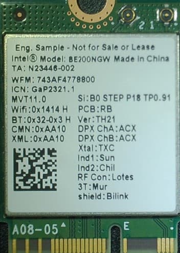
PD9BE200NG
Sep 13, 2023Intel BE200
Equipment Class
6CD - 15E 6 GHz Low Power Dual Client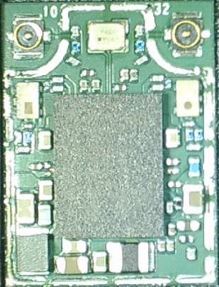
PD9BE200D2
Sep 13, 2023Intel BE200
Equipment Class
6CD - 15E 6 GHz Low Power Dual Client