PD9WM3B2100AMini-PCI Type 3B 802.11a and 802.11b WLAN Adapter
Intel Corporation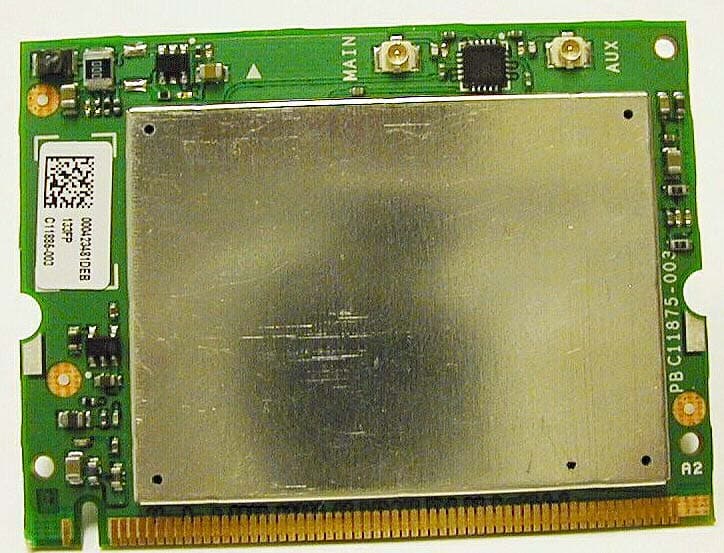
Click to zoom
Application Details
- Equipment Class
- DTS - Digital Transmission System
- Date of Grant
- May 28, 2003
- Application Purpose
- Original Equipment
- Date of Application
- May 28, 2003
- Equipment Note
- Mini-PCI Type 3B 802.11a and 802.11b WLAN Adapter
- Frequency Range
- 2412.00000000 - 2462.00000000
- Company
- Intel Corporation
- Country
- France
Documents & Files
Document Text
Text extracted from the exhibit documents filed with the FCC. Open a document above to read the original.
Users Manual
Calexico I Dual Band (802.11a and 802.11b) Compliance Guidelines Wireless Networking Division Regulatory and Safety Notices User Documentation Guidelines for OEMs and Integrators Calexico I (Dual Band 802.11a and 802.11b) Note: Due to the evolving state of regulations and standards in the wireless LAN field (IEEE 802.11 and similar), the information provided herein is subject to change. Intel Corporation assumes no responsibility for errors or omissions in this document. Nor does Intel make any commitment to update the information contained herein. Created: 02/13/03 Last Updated: 02/24/03 Page 1 Date printed: 2/24/2003 Calexico I Dual Band (802.11a and 802.11b) Compliance Guidelines Revision History Date Changes 02/10/03 Created dual-band document to meet requirements for worldwide compliance submittal on February 14, 2003. 02/24/03 Added FCC statement on restriction to indoor use. Copyright © 2003, Intel Corporation. All rights reserved. Disclaimer: If this pre-release document is supplied under the terms of a non-disclosure agreement with Intel Corporation, it may not be copied or disclosed except in accordance with the terms of that agreement. Intel Corporation assumes no responsibility for errors or omissions in this document. Nor does Intel make any commitment to update the information contained herein. Intel is a registered trademark of Intel Corporation. Other product and corporate names may be trademarks of other companies and are used only for explanation and to the owners' benefit, without intent to infringe. Page 2 Date printed: 2/24/2003 Calexico I Dual Band (802.11a and 802.11b) Compliance Guidelines Intel® PRO/Wireless LAN 2100A Mini PCI Adapters Safety and Regulatory Notices User Documentation Guidelines for OEMs and Integrators Purpose of This Document This document is provided for the information of original equipment manufacturers (OEMs), system integrators, and others who manufacture and distribute systems or products that incorporate a version of the Intel PRO/Wireless LAN 2100A (dual-band 802.11a and 802.11b) Mini PCI adapter. The purpose of the document is to provide safety and regulatory information pertaining to the Intel products of reference and guidance as to what information must be communicated by the OEM/integrator to the end user of the products. As new approval information becomes available over the course of the worldwide approvals process, additional guidelines will be developed as required. Note: This document should not be distributed directly to end users of the Intel products of reference. The format and content of the regulatory information supplied to the end user is the responsibility of the OEM or integrator, and not of Intel. The information in this document applies to the following products: Dual-band wireless LAN adapters (802.11a and 802.11b) Intel® PRO/Wireless LAN 2100A 3B Mini PCI Adapter (model WM3B2100A) Intel® PRO/Wireless LAN 2100A 3A Mini PCI Adapter (model WM3A2100A) Information for OEMs and Integrators The following statement must be included with all versions of this document supplied to an OEM or integrator, but should not be distributed to the end user. • This device is intended for OEM integrators only. • This device cannot be co-located with any other transmitter. • Please refer to the full Grant of Equipment document for other restrictions. This device is intended for OEM integrators only. This device cannot be co-located with any othertransmitter. Information To Be Supplied to the End User by the OEM or Integrator The following regulatory and safety notices must be published in documentation supplied to the end user of the product or system incorporating an Intel® PRO/Wireless LAN 2100A Mini PCI Adapter in compliance with local regulations. Local Restriction of 802.11a and 802.11b Radio Usage The following statement on local restrictions must be published as part of the compliance documentation for all 802.11a and 802.11b products. Caution: Due to the fact that the frequencies used by 802.11a and 802.11b wireless LAN devices may not yet be harmonized in all countries, 802.11a and 802.11b products are designed for use only in specific countries, and are not allowed to be operated in countries other than those of designated use. As a user of these products, you are responsible for ensuring that the products are used only in the countries for which they were intended and for verifying that they are configured with the correct selection of frequency and channel for the country of use. Any deviation from permissible settings and restrictions in the country of use could be an infringement of national law and may be punished as such. FCC Radio Frequency Interference Requirements This device is restricted to indoor use due to its operation in the 5.15 to 5.25 GHz frequency range. FCC requires this product to be used indoors for the frequency range 5.15 to 5.25 GHz to reduce the potential for harmful interference to co-channel Mobile Satellite systems. High power radars are allocated as primary users of the 5.25 to 5.35 GHz and 5.65 to 5.85 GHz bands. These radar stations can cause interference with and /or damage this device. Page 3 Date printed: 2/24/2003 Calexico I Dual Band (802.11a and 802.11b) Compliance Guidelines USA and Canada Safety Requirements and Notices The FCC with its action in ET Docket 93-62 has adopted a safety standard for human exposure to radio frequency (RF) electromagnetic energy emitted by FCC certified equipment. The Intel PRO/Wireless LAN 2100A Mini PCI Adapter products meet the Human Exposure limits found in OET Bulletin 65, 2001, and ANSI/IEEE C95.1, 1992. Proper operation of this radio according to the instructions found in this manual will result in exposure substantially below the FCC’s recommended limits. The following safety precautions should be observed: • Do not touch or move antenna while the unit is transmitting or receiving. • Do not hold any component containing the radio such that the antenna …
Text truncated - open the document above for the full version.
Users Manual
Intel(R) PRO/Wireless LAN Mini PCI Adapter User's Guide This document provides information for the following wireless devices: l Intel(R) PRO/Wireless LAN 2100A 3B Mini PCI Adapter l Intel(R) PRO/Wireless LAN 2100 3B Mini PCI Adapter These wireless adapters operate with high-capacity networks using multiple access points within large or small environments. Using the Intel(R) PROSet Windows utility you can configure, manage wireless local area network (WLAN) management tasks, adapter switching functions, and connections. Wireless LAN General Information About Wireless LAN Technology Adapter Setup and Configuration Software Installation Using Intel(R) PROSet Connecting to a Network Security Overview Setting Up Security Troubleshooting Specifications Glossary Support and Warranty Customer Support Software License Safety and Regulatory Notices Limited Warranty Adapter Registration Legal Notices Copyright (c) 2003 Intel Corporation. All rights reserved. Intel Corporation, 5200 N.E. Elam Young Parkway, Hillsboro, OR 97124-6497 USA Intel Corporation assumes no responsibility for errors or omissions in this document. Nor does Intel make any commitment to update the information contained herein. Intel, Itanium, and Pentium are trademarks or registered trademarks of Intel Corporation or its subsidiaries in the United States and other countries. *Other names and brands may be claimed as the property of others. Back to Contents Page About Wireless LAN Technology l Choosing a WLAN l Configuring a WLAN l Identifying a WLAN l Surveying the Site of Your WLAN l Factors Affecting Range l Stronger Security A wireless network connects computers without using network cables. Computers use radio communications to send data between each other. You can communicate directly with other wireless computers, or connect to an existing network through a wireless access point. When you set up your wireless adapter, you select the operating mode for the kind of wireless network you want. You can use your Intel(R) PRO/Wireless adapter to connect to other similar wireless devices that comply with the 802.11 standard for wireless networking. Choosing a Wireless LAN Mode Wireless LANs can operate with or without access points, depending on the number of users in the network. Infrastructure mode uses access points to allow wireless computers to send and receive information. Wireless computers transmit to the access point, the access point receives the information and rebroadcasts it to other computers. The access point can also connect to a wired network or to the Internet. Multiple access points can work together to provide coverage over a wide area. Peer-to-Peer mode, also called Ad Hoc mode, works without access points and allows wireless computers to send information directly to other wireless computers. You can use Peer-to-Peer mode to network computers in a home or small office or to set up a temporary wireless network for a meeting. Configuring a Wireless LAN There are three basic components that must be configured for a wireless LAN to operate properly: l Network Name—Each wireless network uses a unique Network Name to identify the network. This name is called the Service Set Identifier (SSID). When you set up your wireless adapter, you specify the SSID. If you want to connect to an existing network, you must use the name for that network. If you are setting up your own network you can make up your own name and use it on each computer. The name can be up to 32 characters long and contain letters and numbers. l Profiles—When you set up your computer to access a wireless network, Intel(R) PROSet creates a profile for the wireless settings that you specify. If you want to connect to another network, you can scan for existing networks and make a temporary connection, or create a new profile for that network. After you create profiles, your computer will automatically connect when you change locations. l Security—The 802.11 wireless networks use encryption to help protect your data. Wired equivalent privacy (WEP) uses a 64-bit or 128-bit shared encryption key to scramble data. Before a computer transmits data, it scrambles the data using the secret encryption key. The receiving computer uses this same key to unscramble the data. If you are connecting to an existing network, use the encryption key provided by the administrator of the wireless network. If you are setting up your own network you can make up your own key and use it on each computer. Identifying a Wireless Network Depending on the size and components of a wireless LAN, there are many ways to identify a wireless LAN: l The Network Name or Service Set Identifier (SSID)—Identifies a wireless network. All wireless devices on the network must use the same SSID. l Extended Service Set Identifier (ESSID)—A special case of SSID used to identify a wireless network that includes access points. l Independent Basic Service Set Identifier (IBSSID)—A special case of SSID used to identify a network of wireless computers configured to communicate directly with one another without using an access point. l Basic Service Set Identifier (BSSID)—A unique identifier for each wireless device. The BSSID is the Ethernet MAC address of the device. l Broadcast SSID—An access point can respond to computers sending probe packets with the broadcast SSID. If this feature is enabled on the access point, any wireless user can associate with the access point by using a blank (null) SSID. Surveying the Site of Your Wireless LAN Conducting a site survey for your wireless LAN is the most crucial step in the process of setting up a wireless network. It greatly reduces the amount of troubleshooting you will have to do once you have the wireless LAN set up and ready for connection testing. To conduct a site survey, you will need the following tools: l An access point (or laptop computer) that is set up to be the transmitter. It should be mounted near and at the same height as the designated location…
Text truncated - open the document above for the full version.
Block Diagram
May 9, 2003 American TCB 6731 Whittier Ave. Suite C110 McLean, VA. 22101 RE: Intel FCC ID: PD9WM3B2100A 1.) For the sake of simplicity, please use only one Form 731 for any Composite application. It would be appreciated if a revised form could be uploaded to the AmericanTCB.com website. Responds: Understood. 2.) Both the Internal Photos and the External Photos are too small and not clear enough. 47CFR 2.1033(b)(7) specifies 8” x 10” photographs. It is expected that photographs should be clear enough to easily read major components on the PCB. Responds: New External and Internal Photos Uploaded. 3.) Please address the modular approval concerns of DA 00-1407. Responds: Modular cover letter uploaded 4.) Please provide larger Test Setup photographs [full size landscape orientation would be helpful]. It is not possible to determine compliance with either the modular approval setup requirements of DA 00-1407 or the EMC test setup requirements of ANSI C63.4. Responds: Photos have been place on landscape. New test configuration photos have been provided. 5.) The sample label does not contain an FCC ID. Please provide complete label. Responds: Label with FCC ID has been uploaded. 6.) Two manuals were supplied with this Application. Under what circumstances will one be supplied over the other? Responds: The user guide is what the end user will receive, but it will be implemented in the OEM user guide. The OEM regulatory notices is what we give the OEM integrator for reference to have in their user guide regulatory notice section. So both manuals will be given to the OEM Integrator. 7.) The manual titled “Intel(R) PRO/Wireless LAN Mini PCI Adapter User's Guide” references the use of high gain antennas in a fixed environment with the user required to maintain a minimum of 30cm from the antenna. The MPE report does not refer to any high gain antennas. Please explain. Responds: This reference is under the safety precautions mentioning if a high gain antenna is used the included precautions must be followed, under normal conditions this would not be the case due to this card is planned for use in OEM Laptops. 8.) OEM integration manuals should caution against supplying installation and removal instructions to the end user. Responds: This is on page 5 of the User Documentation Guidelines for OEMs and Integrators. 9.) Please help me find the required information of 15.21. Responds: This is on page 6 of the User Documentation Guidelines for OEMs and Integrators. 10.) Please show how this device will meet the integral antenna requirements of 15.407(d). Responds: In most cases this device will be non accessible to the user. In cases where it is possible that the user may find access by design of the laptop, the connector will be permanently affixed to the MiniPCI module via a suitable permanent connection such as glue, solder, epoxy or any other means to comply with 15.407(d) of the FCC Rules. 11.) Please specify the temperature range and operational frequencies for normal operations . Your Operational Description seems to indicate that this product is capable of transmitting directly on the band edges, and consequently will not meet the requirements of 15.407(g). Responds: For the U.S. the 802.11B radio will only operate on channels 1 – 11 (2.4GHz – 2.462GHz), depending on the country Sku the firmware which is not accessible and can not be changed by the user will be flashed to the specific country channels as shown on page 12 of the Functional Description document. For the U.S. the 802.11A radio will only operate on channels 36 – 64 (5.15GHz – 5.35GHz), depending on the country Sku the firmware which is not accessible and can not be changed by the user will be flashed to the specific country channels as shown on page 12 of the Functional Description document. 12.) Is this dual-band product capable of transmitting in the 2.4 and 5GHz bands simultaneously? Responds: No, it can only operate at one time. 13.) FCC recommends the spectral power density test be performed over a 1.5MHz span. Responds: New PSD measurements have been provided in the report. 14.) The note comments on page 21 of the DTS test report do not seem appropriate to 2.4GHz equipment. Please explain. Responds: Comments have been changed to note correct frequency for 2.4GHz. 15.) Please review the peak excursion data for the UNII report. The quoted value of 2.83dB seems very small for 802.11a emissions. Responds: Peak Excursion has been tested on a separate spectrum analyzer and gave same results (Documents is label “Peak Excursion”. Values measured previously show that they are correct. 16.) FYI: Please note that Parts Lists are not required for any unlicensed Part 15 device. Do you still want the parts list included in this Application? If not, a revised Confidentiality letter will be required. Responds: Yes we understand this and it was given as information only.
ID Label/Location Info
CE mark applicable only with Intel authorized antenna solutions GENERIC WM3B2100A MASTER VERSION This Class B digital apparatus meets all requirements of the Canadian Interference-Causing equipment Regulations. Exxxxxx CUS Approved by IDA for use in Singapore. DBxxxxx FOR HOME OR OFFICE USE Tested to Comply with FCC Standards FCC ID: PD9WM3B2100A Model: WM3B2100A Type: WM3B2100A 0000 CANADA ICES/NMB-003 Class/Classe (B) IC: xxxx xxxxxx TRE-xxx/xxxx/xxxx-xx-xxxx MTC xxxxxxxx CNC: xx-xxxx SUBTEL: xxxxx SCT: xxxxxxxx-xxx Federal regulations restrict use of this component outside of this product. Use only with the Intel supplied antennas designated for this product Potwierdzenie Inr. xxx/xxxx xxxxxxxx CMII ID: xxxxxxxxxx BARCODE AREA MALAYSIA xxxxxx-xxxxxxx
RF Exposure Info
MPE Calculations FCC part 1.1310, Table 1 limits the power density for uncontrolled exposure to 1mW/ cm 2 for systems operating in the UNII bands. The distance, d(cm) from the antenna at which the power density, P d (mW/cm 2 ) is below this limit is calculated from the maximum EIRP, P t (mW) using the equation: P d = P t /(4 pd 2 ) Re-arranging for the distance at which the power density is 1mW/cm2 gives: d = √ (P t /(4 p)) HITACHI ANTENNA(s) Frequency Maximum Output Power (dBm) Max. Antenna Gain (dBi) EIRP (mW) Pd at 20cm Calculated distance (in cm) where Pd < 1mW/ cm2 2412 - 2462 MHz 16.6 0 45.7 0.009 1.9 5180 - 5320 MHz 17.3 0 53.7 0.010 2.1 ETHERTRONICS ANTENNA(s) Frequency Maximum Output Power (dBm) Max. Antenna Gain (dBi) EIRP (mW) Pd at 20cm Calculated distance (in cm) where Pd < 1mW/ cm2 2412 - 2462 MHz 16.6 2.0 72.4 0.014 2.4 5180 - 5320 MHz 17.3 5.0 169.8 0.034 3.7 The minimum distance from the antenna that the power density is 1mW/ cm 2 is, therefore, 2.8 cm for all operating frequencies, based on the use of the Hitachi and Ethertronics antennas detailed for this application. The OEM will be responsible for determining the distance based on the antenna configuration(s) used in their systems. This information is detailed in the OEM compliance guide provided by Intel.
RF Exposure Info
Reference Antenna Kit for Intel ® PRO/Wireless LAN Mini-PCI Adapters The Intel ® PRO/Wireless LAN Mini-PCI adapter (models: 5000, 7100 and 2100) requires an embedded antenna in a notebook PC or other platform where the adapter is used. It is recommended that the antenna have similar characteristics to the antenna specification described in this technical reference sheet. The antenna detailed in this document is designed for operation in both 802.11a and 802.11b radio spectrums (i.e. 2.4 GHz and 5 GHz). Note: only the 5 GHz is required. This antenna is available with a 400mm (20-inch) connect cable from the external vendor as detailed on the back page. The antenna directivity patterns in the azimuth XY and XZ planes are displayed below at both 2.4 GHz and 5.2 GHz. 2.4 GHz (802.11b) Range (Frequency: 2.45 GHz. Power: 5dBm) Vertical Polarization peak gain: -0.88 dBi Horizontal Polarization peak gain: 1.67 dBi XY plane average gain: -2.34 dBi Vertical Polarization peak gain: -0.60 dBi Horizontal Polarization peak gain: -5.11 dBi XZ plane average gain: -4.07 dBi XY Plane XZ Plane 5 GHz (802.11a) Range (Frequency: 5.25 GHz. Power: 5dBm) Vertical Polarization peak gain: -0.78 dBi Horizontal Polarization peak gain: -1.01 dBi XY plane average gain: -3.42 dBi Vertical Polarization peak gain: 4.15 dBi Horizontal Polarization peak gain: -1.50 dBi XZ plane average gain: -1. 81dBi XY Plane XZ Plane Antenna Specifications Copyright 2002, Intel Corporation. All rights reserved. Intel Corporation, 5200 N.E. Elam Young Parkway, Hillsboro, OR 97124-6497 Intel Corporation assumes no responsibility for errors or omissions in this document. Nor does Intel make any commitment to update the information contained herein. Other product and corporate names may be trademarks of other companies and are used only for explanations and to the owners’ benefit, without intent to infringe. Antenna specifications based on Hitachi-Cable antenna. Antenna Cable Measured Gain The Hitachi-Cable dual-band elements were measured with 400mm (20-inch) of coaxial cables. It is estimated that this length of cable attributes ~4 dB of loss. With Cable Loss Without Cable Loss (assumed 4 dB) Percent Gain 2.4 GHz 5.2 GHz 2.4 GHz 5.2 GHz 95% -8.00 dBi -6.7600 dBi -4.00 dBi -2.7600 dBi 90% -2.66 dBi -6.1200 dBi +1.34 dBi -2.1200 dBi 80% -1.23 dBi -3.6900 dBi +2.77 dBi +0.3100 dBi The connector on the opposite end of the connect cable from the antenna, is a Hirose U.FL. connector. This connector cable and antenna assembly is designed specifically for use with Intel ® PRO/Wireless 5000, 7100 and 2100 Mini-PCI Adapters. The cable specifications are: • Diameter 1.13 mm • Length 400 mm Frequency Range 802.11b – 2.4 – 2.5 GHz 802.11a – 5.15 – 5.35 GHz Nominal Peak Antenna Gain 0 dBi Polarization Linear, vertical Input VSWR <2.0:1 Max Input Feedpoint Impedance 50 ohms Maximum Power Input 10 watts Static Protection Element and Feed are recommended Regulatory Approvals FCC Parts 15B and 68, UL, C-UL, Industry Canada, CE Approval, VCCI (Japan), ETSI. Width 30.98 mm Length 30.54 mm Height 1.29 mm To Hirose U.FL Connector Elevation Plane Azimuth Plane Aki Kenmotsu - Hitachi Cable America, Inc. 3625 Del Amo Blvd., Suite 385. Torrance, CA 90503 Phone (310) 542-9680 - Fax (310) 542-9610 Volume Purchasing Contact Information Hitachi Long Antenna Assembly. Part Number - HFD01-IT02 The Hitachi-Cable antenna is constructed from rolled copper with Kapton tape on both sides. This configuration yields thin radiating elements. A Hitachi-Cable coax is directly soldered to the structure as shown above. The antenna can be mounted in the rear of the laptop LCD panel. The following shows the 2.4 GHz and 5 GHz Band Free-Space Azimuth Pattern. Hirose U.FL Connector
Test Report
File: R51032 Page 1 of 17 Electromagnetic Emissions Test Report and Application for Grant of Equipment Authorization pursuant to FCC Part 15, Subpart C Specifications for an Intentional Radiator on the Intel Corporation Model: WM3B2100A FCC ID: PD9WM3B2100A GRANTEE: Intel Corporation 2300 Corporate Center Drive Thousand Oaks, CA 91320 TEST SITE: Elliott Laboratories, Inc. 684 W. Maude Avenue Sunnyvale, CA 94086 REPORT DATE: April 29, 2003 FINAL TEST DATE: April 23 and April 24, 2003 AUTHORIZED SIGNATORY: ______________________________ Juan Martinez Sr. EMC Engineer Elliott Laboratories, Inc. is accredited by the A2LA, certificate number 2016-01, to perform the test(s) listed in this report. This report shall not be reproduced, except in its entirety, without the written approval of Elliott Laboratories, Inc. Elliott Laboratories, Inc. -- EMC Department Test Report Report Date: April 29, 2003 File: R51032 Page 2 of 17 Pages TABLE OF CONTENTS COVER PAGE...................................................................................................................................................................................1 APPLICATION AND AGREEMENT FOR CERTIFICATION SERVICES.........................................................................1 TABLE OF CONTENTS..............................................................................................................................................................2 DECLARATIONS OF COMPLIANCE......................................................................................................................................3 SCOPE............................................................................................................................................................................................4 OBJECTIVE...................................................................................................................................................................................4 STATEMENT OF COMPLIANCE..............................................................................................................................................4 SUMMARY OF RESULTS...........................................................................................................................................................5 MEASUREMENT UNCERTAINTIES....................................................................................................................................6 EQUIPMENT UNDER TEST (EUT) DETAILS..........................................................................................................................7 GENERAL...................................................................................................................................................................................7 OTHER EUT DETAILS.............................................................................................................................................................7 ENCLOSURE..............................................................................................................................................................................7 MODIFICATIONS.....................................................................................................................................................................7 SUPPORT EQUIPMENT...........................................................................................................................................................7 EUT INTERFACE PORTS........................................................................................................................................................8 EUT OPERATION DURING TESTING...................................................................................................................................8 TEST SITE......................................................................................................................................................................................9 GENERAL INFORMATION.....................................................................................................................................................9 CONDUCTED EMISSIONS CONSIDERATIONS.................................................................................................................9 RADIATED EMISSIONS CONSIDERATIONS....................................................................................................................9 MEASUREMENT INSTRUMENTATION................................................................................................................................10 INSTRUMENT CONTROL COMPUTER.............................................................................................................................10 LINE IMPEDANCE STABILIZATION NETWORK (LISN)..............................................................................................10 POWER METER......................................................................................................................................................................11 FILTERS/ATTENUATORS....................................................................................................................................................11 ANTENNAS.............................................................................................................................................................................11 ANTENNA MAST AND EQUIPMENT TURNTABLE.....................................................................................................11 INSTRUMENT CALIBRATION............................................................................................................................................11 TEST PROCEDURES.........................................................................................................................................…
Text truncated - open the document above for the full version.
Test Setup Photos
MINI PCI CARD OUTSIDE THE HOST SYSTEM
Contact Information
Applicant
Benjamin Lavenant(Regulatory Engineer)
Technical Contact
Elliott Laboratories Inc.Juan Martinez
[email protected]408 245 7800
684 West Maude Avenue · Sunnyvale, California · United States
Test Firm
Elliott Laboratories Inc.David Bare
Technical Specifications
| # | Rule Parts | Frequency Range | Power Output |
|---|---|---|---|
| 1 | 15C | 2.41 GHz - 2.46 GHz | 45.00 mW |
Other Applications from Intel Corporation
PD9BE201D2P
Aug 20, 2024Intel BE201D2WP
Equipment Class
NII - Unlicensed National Information Infrastructure TXPD9AX411NG
Jul 02, 2024Intel WiFi 6E AX411
Equipment Class
6CD - 15E 6 GHz Low Power Dual ClientPD9AX211D2H
Jan 28, 2024Intel Wi-Fi 6E AX211
Equipment Class
DSS - Part 15 Spread Spectrum Transmitter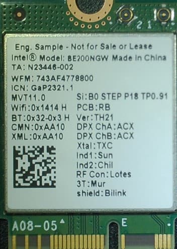
PD9BE200NG
Sep 13, 2023Intel BE200
Equipment Class
6CD - 15E 6 GHz Low Power Dual Client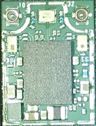
PD9BE200D2
Sep 13, 2023Intel BE200
Equipment Class
6CD - 15E 6 GHz Low Power Dual Client