PD9WM3B2200BGPRO/Wireless 2200BG
Intel Corporation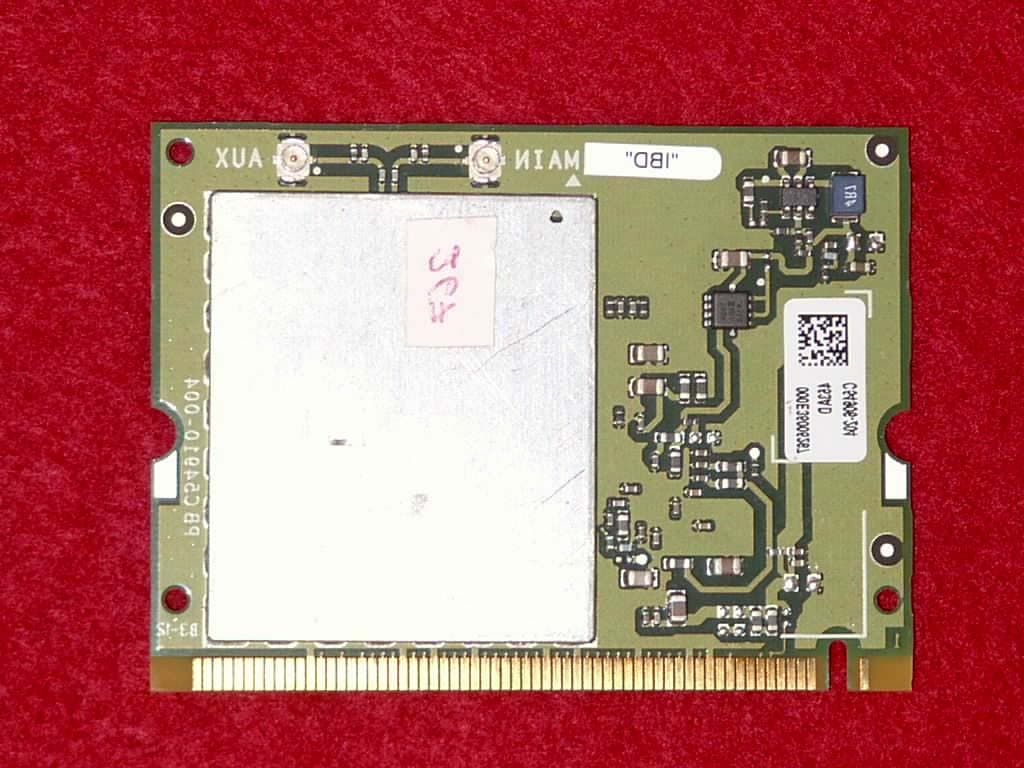
Click to zoom
Application Details
- Equipment Class
- DTS - Digital Transmission System
- Date of Grant
- Dec 11, 2003
- Application Purpose
- Original Equipment
- Date of Application
- Dec 11, 2003
- Equipment Note
- PRO/Wireless 2200BG
- Frequency Range
- 2412.00000000 - 2462.00000000
- Company
- Intel Corporation
- Country
- France
Documents & Files
Document Text
Text extracted from the exhibit documents filed with the FCC. Open a document above to read the original.
Users Manual
Intel(R) PRO/Wireless 2200BG User's Guide Your Intel(R) PRO/Wireless 2200BG Network Connection adapter works with either 802.11b or 802.11g wireless standard. Operating at 2.4 GHz frequency at speeds of up to 54 Mbps you can now connect your computer to high-capacity existing 802.11b networks using multiple access points within large or small environments, and also to high-speed 802.11g networks. Your wireless adapter maintains automatic data rate control according to access point location to achieve the fastest possible connection. All your wireless client connections can be easily managed by the Intel(R) PROSet for Wireless utility. Using the Intel(R) PROSet for Wireless Profile Wizard, you can create profiles automatically to suite your specific connection requirements. Enhanced security measures using 802.1x, WPA encryption and authentication, and 128-bit WEP encryption is standard for both 802.11b and 802.11g. Introduction to Wireless Networking Software Installation Using Intel(R) PROSet for Wireless Connecting to a Network Security Overview Setting up Connection Security Troubleshooting Specifications Glossary Customer Support Safety and Regulatory Notices Warranty Adapter Registration Information in this document is subject to change without notice. (c) 2000–2003 Intel Corporation. All rights reserved. Intel Corporation, 5200 N.E. Elam Young Parkway, Hillsboro, OR 97124-6497 USA The copying or reproducing of any material in this document in any manner whatsoever without the written permission of Intel Corporation is strictly forbidden. Intel(R) is a trademark or registered trademark of Intel Corporation or its subsidiaries in the United States and other countries. Other trademarks and trade names may be used in this document to refer to either the entities claiming the marks and names or their products. Intel disclaims any proprietary interest in trademarks and trade names other than its own. Microsoft and Windows are registered trademarks of Microsoft Corporation. *Other names and brands may be claimed as the property of others. Intel Corporation assumes no responsibility for errors or omissions in this document. Nor does Intel make any commitment to update the information contained herein. September 2003 Back to Contents Page Wireless LAN Overview: Intel(R) PRO/Wireless 2200BG User's Guide About Wireless LAN Technology l Choosing a WLAN l Configuring a WLAN l Identifying a WLAN l Surveying the Site of Your WLAN l Factors Affecting Range A wireless network connects computers without using network cables. Computers use radio communications to send data between each other. You can communicate directly with other wireless computers, or connect to an existing network through a wireless access point. When you set up your wireless adapter, you select the operating mode for the kind of wireless network you want. You can use your wireless adapter to connect to other similar wireless devices that comply with the 802.11 standard for wireless networking. Choosing a Wireless LAN Wireless LANs can operate with or without access points, depending on the number of users in the network. Infrastructure mode uses access points to allow wireless computers to send and receive information. Wireless computers transmit to the access point, the access point receives the information and rebroadcasts it to other computers. The access point can also connect to a wired network or to the Internet. Multiple access points can work together to provide coverage over a wide area. Peer-to-Peer mode, also called Ad Hoc mode, works without access points and allows wireless computers to send information directly to other wireless computers. Ad Hoc Mode is only supported in 802.11b and 802.11g networks. You can use Peer-to-Peer mode to network computers in a home or small office or to set up a temporary wireless network for a meeting. Configuring a Wireless LAN There are three basic components that must be configured for an 802.11 wireless LAN to operate properly: l Network Name: Each wireless network uses a unique Network Name to identify the network. This name is called the Service Set Identifier (SSID). When you set up your wireless adapter, you specify the SSID. If you want to connect to an existing network, you must use the name for that network. If you are setting up your own network you can make up your own name and use it on each computer. The name can be up to 32 characters long and contain letters and numbers. l Profiles: When you set up your computer to access a wireless network, the wireless client manager creates a profile for the wireless settings that you specify. If you want to connect to another network, you can scan for existing networks and make a temporary connection, or create a new profile for that network. After you create profiles, your computer will automatically connect when you change locations. l Security: The 802.11 wireless networks use encryption to help protect your data. Wired equivalent privacy (WEP) uses a 64-bit or 128-bit shared encryption key to scramble data. Before a computer transmits data, it scrambles the data using the secret encryption key. The receiving computer uses this same key to unscramble the data. If you are connecting to an existing network, use the encryption key provided by the administrator of the wireless network. If you are setting up your own network you can make up your own key and use it on each computer. m Wi-Fi Protected Access (WPA) is a security enhancement that strongly increases the level of data protection and access control to a WLAN. WPA mode enforces 802.1x authentication and key-exchange to strengthen data encryption. WPA utilizes its Temporal Key Integrity Protocol (TKIP). TKIP provides important data encryption enhancements that include a per-packet key mixing function, a message integrity check (MIC) named "Michael", an extended initialization vector (IV) with sequencing rules, and a also re-keying mechanism. Using these improvement enhanceme…
Text truncated - open the document above for the full version.
Cover Letter(s)
AEGIS LABS, INC 22431 Antonio Parkway B160-417, Rancho Santa Margarita, CA 92688 949-459-7886 TEL 949-459-7869 FAX www.aegislabsinc.com TRANSMITTER MODULAR APPROVAL ATTESTATION November 19, 2003 Federal Communications Commission Re: Application Modular Approval Certification for FCC ID: PD9WM3B2200BG Gentlemen: The following attestation addresses the eight requirements to support modular approval as required by the FCC Public Notice DA00-1407 “Part 15 Unlicensed Modular Transmitter Approval” 1 The modular transmitter has its own RF shielding and does not rely upon the shielding provided by the device into which it is installed in order to comply with Part 15 limits. 2 The modular transmitter has buffered modulation/data inputs. All inputs to the modules are buffered through the radio circuitry. 3 The modular transmitter has its own power supply regulator. 4 The modular transmitter has an antenna that complies with section 15.203 and 15.204(c) of the FCC rules. It has a UFL type of connector at the transmitter end and is soldered to the antenna (depending on OEM configuration). Also the antenna will be internal in the OEM host equipment and inaccessible to the user. 5 The modular transmitter was tested outside of a host desktop computer using a PCI extender card. The PCI extender card allows the transmitter to be placed outside of the chassis of the host desktop computer. 6 The modular transmitter will be labeled with its own FCC ID. Also, the OEM host computer manufacturer will be informed to display a label referring to the enclosed module. The exterior label will read as follows: “Contains Transmitter Module FCC ID” or “Contains TXFCCID”. 7 The modular transmitter is manufactured so that the user cannot influence the operation of the transmitter that will operate outside of the scope of the regulations. 8 The modular transmitter meets the MPE calculations of 47 CFR 1.1307(b)(1). Also, SAR data is available if necessary. If there are any additional questions or if further information is needed, please contact us at your earliest convenience at (949) 459-7886. Sincerely, Rick Candelas Aegis Labs, Inc. Lab Manager
Cover Letter(s)
November 19, 2003 American TCB 6731 Whittier Ave., Suite C110 McLean, VA 22101 Gentlemen: The attached documentation is provided in support of a formal submission to your organization for a modular approval of an intentional unlicensed transmitter. On behalf of our client, Aegis Labs has included an application for a Grant of Equipment Authorization pursuant to Subpart C of part 15 of FCC Rules (47 CFR) regarding intentional radiators. The data within the test report demonstrates the equipment was tested in a manner described under Part 2 and 15 of the Code of Federal Regulations. This is a modular approval of the 802.11b/g MiniPCI Type 3B Wireless Adapter (MN: WM3B2200BG, FCC ID: PD9WM3B2200BG), which is a dual band WLAN adapter (802.11b and 802.11g). It was tested externally to a computer chassis with a set of Hitachi and Ethertronics multi-band antennas continuously transmitting and receiving form the MAIN and AUX antenna ports. If there are any additional questions or if further information is needed, please contact us at your earliest convenience. Sincerely, Rick Candelas Aegis Labs, Inc. Lab Manager Enclosure (1 Emissions Test Report + Exhibits) AEGIS LABS, INC 22431 Antonio Parkway B160-417, Rancho Santa Margarita, CA 92688 949-459-7886 TEL 949-459-7869 FAX www.aegislabsinc.com
Cover Letter(s)
American Telecommunications Certification Body Inc. 6731 Whittier Ave, McLean, VA 22101 November 24, 2003 RE: FCC ID: PD9WM3B2200BG I have a few comments on this Application. 1. Please fill in the technical contact information fields on the 731. 2. Please note that you have put the grantee code in the equipment code field. Please note that the equipment code for this type device is DTS. Please correct the 731 to show the proper equipment code. 3. Please note that the users guide appears to be the guide to the end user. Please provide the OEM installation guide for this mobile module. 4. FYI - no action needed . Please note that this module is restricted to mobile installations only. 5. Please note that the test setup photos are not clear and they appear that the module is located inside the desk top. Please note that this makes the application an LMA for the specific desktop. For a full modular approval, the module MUST be tested in stand alone configuration. Please revise your application for LMA, or alternately, please test the module in stand alone configuration. 6. Please explain the copper tape in the setup photo. Is this needed for compliance? How will this be implemented? If it is not needed, please remove it and retest the device without the copper tape. 7. It appears that the antenna(s) are mounted to a large metal frame. This may affect the radiation pattern and most likely affect radiated emissions. Please explain why this large metal frame was used. If this is not part of the normal antenna configuration, please remove the metal frame and retest in a normal antenna configuration. If this is part of the normal antenna configuration, please provide information on this in the OEM installers guide. 8. Please explain why the desktop PC is laying on its side during testing. 9. There appears to be more than ample room on the label to place the 2-condition statement. Please explain why this statement in not on the label. Alternately, please provide a label with the 2 condition statement. 10. Please provide a photo or drawing showing where the label will be placed. Please provide an explanation of how the label is permanently affixed to the device. 11. Please note that you have used CISPR22/EN55022 limits for radiated emissions. Please note that while CISPR limits may be used for part 15 unintentional radiators they may not be used for intentional radiators. Please recalculate your radiated emissions using the intentional radiator limits of 15.209. 12. FYI – No action needed. For PPSD measurements the video bandwidth is usually set to the same as the RBW (i.e.3kHz). 13. I believe that most mini PCI cards use reverse SMA connectors, however, the schematics for this device show UFL connectors. Please verify/explain. Dennis Ward mailto:[email protected] The items indicated above must be submitted before processing can continue on the above referenced application. Failure to provide the requested information may result in application termination. Correspondence should be considered part of the permanent submission and may be viewed from the Internet after a Grant of Equipment Authorization is issued. z Page 2 November 24, 2003 Please do not respond to this correspondence using the email reply button. In order for your response to be processed expeditiously, you must submit your documents through the AmericanTCB.com website. Also, please note that partial responses increase processing time and should not be submitted. Any questions about the content of this correspondence should be directed to the sender.
Cover Letter(s)
December 10, 2003 RE: Intel Corporation FCC ID: PD9WM3B2200BG Answers to the ATCB comments on the above referenced Application. 1. Please fill in the technical contact information fields on the 731. Refer to “Form 731 (Rev. A, 11-25-03)” 2. Please note that you have put the grantee code in the equipment code field. Please note that the equipment code for this type device is DTS. Please correct the 731 to show the proper equipment code. Refer to “Form 731 (Rev. A, 11-25-03)” 3. Please note that the users guide appears to be the guide to the end user. Please provide the OEM installation guide for this mobile module. The OEM will have their own specific instructions as all laptop vendors will have different locations of where the WLAN card is placed. Since Intel does not make the OEM laptops, Intel cannot provide the OEM installation instruction for all the OEM vendors. 5. Please note that the test setup photos are not clear and they appear that the module is located inside the desktop. Please note that this makes the application an LMA for the specific desktop. For a full modular approval, the module MUST be tested in standalone configuration. Please revise your application for LMA, or alternately, please test the module in standalone configuration. The module was tested in a standalone configuration. It was installed outside the host computer chassis. Refer to “Photographs – Test Setup (Close up)”. 6. Please explain the copper tape in the setup photo. Is this needed for compliance? How will this be implemented? If it is not needed, please remove it and retest the device without the copper tape. The copper tape was installed because a PCI extender board was placed in the host computer PCI slot in order to bring the PCI slot outside the computer chassis. The copper tape is to simulate a PCI slot bracket. 7. It appears that the antenna(s) are mounted to a large metal frame. This may affect the radiation pattern and most likely affect radiated emissions. Please explain why this large metal frame was used. If this is not part of the normal antenna configuration, please remove the metal frame and retest in a normal antenna configuration. If this is part of the normal antenna configuration, please provide information on this in the OEM installer’s guide. The large metal frame simulates an LCD laptop screen and is needed to load the antennas for the purpose of the radiation pattern. 8. Please explain why the desktop PC is laying on its side during testing. This was the easiest way to mount the antennas above the WLAN module to better simulate a notebook computer. 9. There appears to be more than ample room on the label to place the 2-condition statement. Please explain why this statement in not on the label. Alternately, please provide a label with the 2-condition statement. The 2-condition statement will be provided in the manual. Refer to pages 87 & 88 Regulatory of the “User’s Guide” 10. Please provide a photo or drawing showing where the label will be placed. Please provide an explanation of how the label is permanently affixed to the device. The label covers the whole card on both front and back. Refer to “Photograph – Label Placement”. This label is not the correct exact label but will be placed in the same manner. For the correct label refer to “Label1” & Label2”. 11. Please note that you have used CISPR22/EN55022 limits for radiated emissions. Please note that while CISPR limits may be used for part 15 unintentional radiators they may not be used for intentional radiators. Please recalculate your radiated emissions using the intentional radiator limits of 15.209. Refer to “Test Report – EMC (Rev. B, 12-08-03) 13. I believe that most mini PCI cards use reverse SMA connectors, however, the schematics for this device show UFL connectors. Please verify/explain. The mini PCI WLAN device use UFL connectors not reverse SMA connectors.
External Photos
Top View “With Shield” Bottom View
Internal Photos
Top View “Shielding removed”
RF Exposure Info
MPE Calculations Systems operating under the provision of 47 CFR 1.1307(b)(1) shall be operated in a manor that ensures that the public is not exposed to radio frequency energy levels in excess of the FCC guidelines. The EUT will only be used with a separation of 20 centimeters or greater between the antenna and the body of the user or nearby persons and can therefore be considered a mobile transmitter per 47 CFR 2.1091(b). The MPE calculation for this exposure is shown below. Using the Hitachi Antennas: The peak radiated output power (EIRP) is calculated as follows: EIRP = P + G EIRP = 17.51 dBm + 1.67 dBi EIRP = 19.18 dBm (82.79mW) Where P = Power input to the antenna (mW). G = Power gain of the antenna (dBi) Power density at the specific separation: S = PG/(4R 2 π) S = (56.36 x 1.469) / (4 x 20 2 x π) S = 0.016 mW/cm 2 Where S = Maximum power density (mW/cm 2 ) P = Power input to the antenna (mW). G = Numeric power gain of the antenna R = Distance to the center of the radiation of the antenna (20cm = limit for MPE) The maximum permissible exposure (MPE) for the general population is 1mW/cm 2 . The power density at 20cm does not exceed the 1mW/cm 2 limit. Therefore, the exposure condition is compliant with FCC rules. Estimated safe separation: R = PG/4π R = (56.36 x 1.469) / 4π R = 2.57 cm Where P = Power input to the antenna (mW). G = Numeric power gain of the antenna R = The safe estimated separation that the user must maintain from the antenna (cm) The numeric gain (G) of the antenna with a gain specified in dB is determined by: G = Log -1 (dB antenna gain/10) G = Log -1 (1.67 dBi/10) G = 1.469 Using the Ethertronics Antennas: The peak radiated output power (EIRP) is calculated as follows: EIRP = P + G EIRP = 17.51 dBm + 2.00 dBi EIRP = 19.51 dBm (89.33 mW) Where P = Power input to the antenna (mW). G = Power gain of the antenna (dBi) Power density at the specific separation: S = PG/(4R 2 π) S = (56.36 x 1.585) / (4 x 20 2 x π) S = 0.018 mW/cm 2 Where S = Maximum power density (mW/cm 2 ) P = Power input to the antenna (mW). G = Numeric power gain of the antenna R = Distance to the center of the radiation of the antenna (20cm = limit for MPE) The maximum permissible exposure (MPE) for the general population is 1mW/cm 2 . The power density at 20cm does not exceed the 1mW/cm 2 limit. Therefore, the exposure condition is compliant with FCC rules. Estimated safe separation: R = PG/4π R = (56.36 x 1.585) / 4π R = 2.67 cm Where P = Power input to the antenna (mW). G = Numeric power gain of the antenna R = The safe estimated separation that the user must maintain from the antenna (cm) The numeric gain (G) of the antenna with a gain specified in dB is determined by: G = Log -1 (dB antenna gain/10) G = Log -1 (2.00 dBi/10) G = 1.585
Test Report
Page 1 of 15 Report Number: INTEL-031111F FCC ID: PD9WM3B2200BG Modular Approval Test Report And Application for Grant of Equipment Authorization Pertaining To: EUT FCC ID: 802.11b/g MiniPCI Type 3B Wireless Adapter, MN: WM3B2200BG PD9WM3B2200BG Configuration 802.11b / 802.11g MEASUREMENTS PERFORMED IN ACCORDANCE WITH Regulatory Standard(s) 47 CFR Part 15, Subpart C Section 15.247 Test Method: ANSI C63.4: 1992 American National Standard for Methods of Measurement of Radio-Noise Emissions from Low- Voltage Electrical and Electronic Equipment in the Range of 9 kHz to 40 GHz Certificate Number: 1111.01 APPLICANT: PREPARED BY: Intel Corporation Aegis Labs, Inc. EC2-02 13280 Evening Creek Drive 22431 Antonio Parkway B160-417 San Diego, California 92128 Rancho S. Margarita, CA 92688 Contact(s): Mr. James K. Baer Agent(s): Mr. Steve Kuiper Mr. Rick Candelas Test Report #: INTEL-031111F APPENDICES REPORT BODY A TOTAL PAGES PAGES 15 81 96 Test Report Revision: Rev. C, 12-12-2003 The contents of this report shall not be reproduced except in full, without the written approval of Aegis Labs, Inc. Page 2 of 15 Report Number: INTEL-031111F FCC ID: PD9WM3B2200BG TABLE OF CONTENTS SECTION TITLE PAGE COVER SHEET.................................................................................... 01 TABLE OF CONTENTS............................................................................................... 02 1.0 CERTIFICATION OF TEST DATA............................................................................. 03 2.0 SUMMARY OF TEST RESULTS.............................................................. 04 3.0 ADMINISTRATIVE DATA AND TEST DESCRIPTION.......................................... 05 4.0 DESCRIPTION OF EUT..................................................................................... 06 4.1 EUT Description..................................................................................... 06 4.1.1 Channel Number and Frequencies................................................................ 07 4.2 EUT Configuration.................................................................................. 08 4.3 List of EUT Sub-Assemblies and Host Equipment...................................................... 09 4.4 I/O Cabling Diagram and Description............................................................................. 10 5.0 TEST EQUIPMENT AND TEST SETUPS............................................................... 11 5.1 AC Power Line Conducted Emissions............................................................ 11 5.2 Spurious Radiated Emissions...................................................................... 12 5.3 Conducted Emissions At The Antenna Port.................................................................... 12 5.4 Test and Measurement Equipment Used......................................................... 13 6.0 SAMPLE CALCULATIONS.......................................................................................... 14 7.0 MODIFICATIONS AND RECOMMENDATIONS........................................ 15 APPENDICES A Test Data Page 3 of 15 Report Number: INTEL-031111F FCC ID: PD9WM3B2200BG 1.0 CERTIFICATION OF TEST DATA Aegis Labs, Inc. operates as both a Nevada and California Corporation with no organizational or financial relationship with any company, institution, or private individual. Testing and engineering functions provided by Aegis Labs are furnished through the use of part-time, full-time or consulting engineers with the appropriate qualifications to carry out their duties. The intended purpose of this test report is to describe the measurement procedure and to determine whether the equipment under test “EUT” complies with both the conducted and radiated limits. Limits for emissions testing are described under Subpart C of Part 15 of the FCC rules. The data, data evaluation and equipment configuration represented herein are a true and accurate representation of the Equipment Under Test (EUT) under the requirements specified in the emissions standard as described below. The test results contained in this report are only representative of the test sample tested as described in Section 3.0 of this report. Certification of the EUT is required as a prerequisite to marketing as defined in Part 2 of the FCC Rules. Prepared By: ________________________11/19/03 Rick Candelas Date: Staff Engineer Aegis Labs, Inc. Report Approved By: ________________________11/19/03 Steve J. Kuiper Date: Quality Assurance Manager Aegis Labs, Inc. Page 4 of 15 Report Number: INTEL-031111F FCC ID: PD9WM3B2200BG 2.0 SUMMARY OF TEST RESULTS The test results provided within this report, indicate that the EUT has been found to be in COMPLIANCE with the test specifications based upon the following RF compliance standards: Pass/Fail determination is based upon the nominal values of the test data. EMISSIONS STANDARD FCC Part 15 Section Description Results Comments 15.247(a)(2) The minimum 6dB bandwidth shall be at least 500 kHz. PASSED See Data Sheets 15.247(b)(1) The maximum peak output power of the intentional radiator shall not exceed 1 watt. PASSED See Data Sheets 15.247(b)(4) The intentional radiator shall be operated in a manner that ensures that the public is not exposed to radio frequency energy levels in excess of the FCC guidelines per Section 1.1307(b)(1). PASSED Refer to MPE Calculations Exhibit 15.247(c) In any 100 kHz bandwidth outside the frequency band in which the spread spectrum intentional radiator is operating, the radio frequency power that is produced by the intentional radiator shall be at least 20 dB below that in the 100 kHz bandwidth within the band that contains the highest level of the desired power. PASSED See Data Sheets 15.247(c) Radiated emissions, which fall in the restricted bands, as defined in Sec. 15.205(a), must also comply with the radiated emission limits specified in Sec. 15.209(a). All others must be < -20dBc. PASSED See Data Sheets 15.247(d) T…
Text truncated - open the document above for the full version.
Test Setup Photos
Maximum Peak Output Power Measurement Setup Conducted Emissions at Antenna Terminal Setup AC Conducted Emissions Measurement (Front View) Setup AC Conducted Emissions Measurement (Rear View) Setup Radiated Emissions Measurement (30-1000 MHz) (Front View) Setup Radiated Emissions Measurement (30-1000 MHz) (Rear View) Setup Radiated Emissions Measurement (1-26.5 GHz) (Front View) Setup Radiated Emissions Measurement (1-26.5 GHz) (Rear View) Setup
Test Setup Photos
Test Setup “Close Up”
Contact Information
Applicant
Benjamin Lavenant(Regulatory Engineer)
Technical Contact
Aegis Labs, Inc.Rick Candelas
[email protected]949) 459-7886
22431-B160 Antonio Parkway #417 · Rancho Santa Margarita, California · United States
Test Firm
Aegis Labs, Inc.Rick Candelas
Technical Specifications
| # | Rule Parts | Frequency Range | Power Output |
|---|---|---|---|
| 1 | 15C | 2.41 GHz - 2.46 GHz | 56.00 mW |
Other Applications from Intel Corporation
PD9BE201D2P
Aug 20, 2024Intel BE201D2WP
Equipment Class
NII - Unlicensed National Information Infrastructure TXPD9AX411NG
Jul 02, 2024Intel WiFi 6E AX411
Equipment Class
6CD - 15E 6 GHz Low Power Dual ClientPD9AX211D2H
Jan 28, 2024Intel Wi-Fi 6E AX211
Equipment Class
DSS - Part 15 Spread Spectrum Transmitter
PD9BE200NG
Sep 13, 2023Intel BE200
Equipment Class
6CD - 15E 6 GHz Low Power Dual Client
PD9BE200D2
Sep 13, 2023Intel BE200
Equipment Class
6CD - 15E 6 GHz Low Power Dual Client