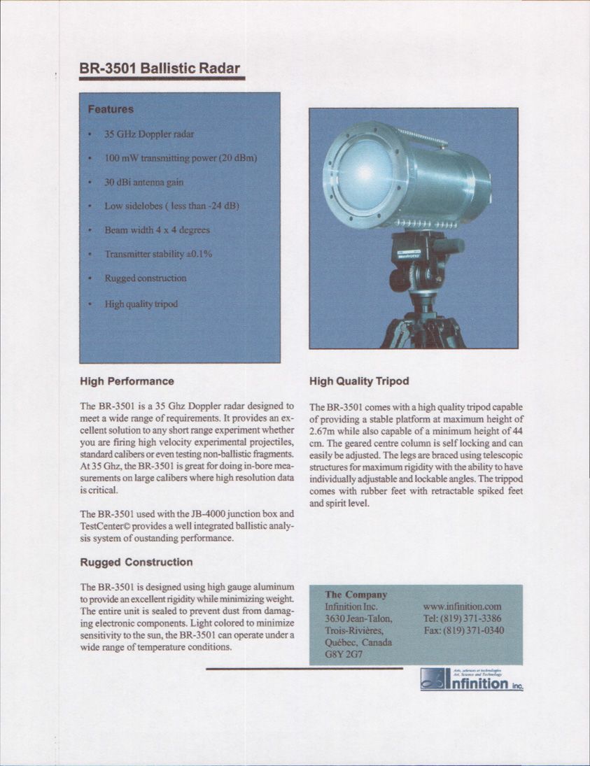
PDGBR-3501BR-3501 35 GHz Doppler Radar
Infinition Inc
Click to zoom
Application Details
- Equipment Class
- TNB - Licensed Non-Broadcast Station Transmitter
- Date of Grant
- Apr 11, 2001
- Application Purpose
- Original Equipment
- Date of Application
- Jan 08, 2001
- Equipment Note
- BR-3501 35 GHz Doppler Radar
- Frequency Range
- 34800.00000000 - 35200.00000000
- Company
- Infinition Inc
- Country
- Canada
Documents & Files
Document Text
Text extracted from the exhibit documents filed with the FCC. Open a document above to read the original.
Users Manual
BR-3501 User Manual Warning Based on the recommendations of the National Council on Radiation Protection and Measurements (NCRP) in occupational/controlled situations, continued exposure to radiation should be avoided within 1 meter in front of the radar. Radiation levels outside this region fall within regulations of 5 mW/cm 2 (for periods less than 6 minutes) and are not considered safety hazards. Direct visual contact with the radar when transmitting should be avoided at all times. Specifications Installation The BR-3501 radar system includes the following three components: ï Radar antenna ï Tripod ï Tripod mounting adapter Before attempting to install your radar, you should familiarize yourself with your new tripod and under- stand how the mounting adapter can be secured in place to hold the radar. Installation Steps: ï Adjust your tripod to a convenient height and orientation. ï Install the tripod mounting adapter under the base of the radar. ï Mount the radar on the tripod ensuring that the mounting adapter is properly locked in place. ï Adjust the radar height, tilt and inclination to your needs using the tripod controls. Operating Frequency35 GHz Transmitting Power100 mW Antenna Gain30 dBi Transmitter Stability±0.1% Beam Width4 ∞ x 4∞ Side Lobes-24 dB Weight12 Kg ! Operation The BR-3501 rear panel contains only three components: Power/Signal Connector The BR-3501 is interfaced to a processing unit using a single six-wire cable equipped with military connectors. This cable is used to provide power to the antenna, to carry the radar doppler signal to the processing unit and to carry the antenna transmission control. You should connect your radar cable from this connector to the appropiate radar input on your processing unit. The connector type is ITT Cannon MS3124E16-8P. The following table discribes the pinout of this connector: The remote activation of the transmitter can be achieved by short circuiting pins D and E of the connec- tor. Transmitter Switch The transmitter switch controls the state of the radar transmitter. When set to On, the radar will transmit the radar signal. When set to Remote, the radar will not actually transmit until the system is armed. The armed state is controlled by the processing unit via the Power/Signal cable. Gain Adjustment Knob Depending on the type of projectile being tested, the amplitude of the return signal may vary greatly. Just think of the returned signal of a 155mm projectile versus the returned signal of a 2mm fragment. Typical Doppler processing units have a minimum dynamic range of 72 dB . The gain adjustment allows you to control the level of amplification applied to the returned signal before it is output to a processing unit. The gain adjustment knob provides nine (9) gain levels ranging from 10 dB up to 90 dB. Having control over the gain allows you to avoid very strong signals from being amplified outside the supported dy- namic range which would lead to a loss of information when processing. Similarly, it allows you to maximize the gain applied to a very weak signal returned by a small projectile. Pin Function AAC Neutral B110 Volts AC CNot Connected DRemote Make (+ 5 Vdc Output) EMake Ground FDoppler Signal + (5 Vpp max.) GDoppler Signal - (5 Vpp max.) HGround
Users Manual
BR-3501 User Manual Safety Warning Based on limits specified by the Federal Communication Commission (FCC) on Radio Fre- quency (RF) emissions in a general population environment, continued exposure to radiation should be avoided within 1.1 meter in front of the radar. Radiation levels outside this region fall within regulations of 1 mW/cm 2 and are not considered safety hazards. When setting up the antenna, special care should be taken to avoid situations where the antenna radiates towards individuals. The antenna should be positioned such that bystanders are located behind the antenna. During antenna setup, the antenna power cord should be unplugged to avoid accidental hazardous exposures to radiations. Always turn the antenna transmitter off during periods of inactivity. Specifications Installation The BR-3501 radar system includes the following three components: • Radar antenna • Tripod • Tripod mounting adapter Before attempting to install your radar, you should familiarize yourself with your new tripod and under- stand how the mounting adapter can be secured in place to hold the radar. Installation Steps: • Adjust your tripod to a convenient height and orientation. • Install the tripod mounting adapter under the base of the radar. • Mount the radar on the tripod ensuring that the mounting adapter is properly locked in place. • Adjust the radar height, tilt and inclination to you needs using the tripod controls. Operating Frequency35 GHz Nominal Transmitting Power100 mW Antenna Gain30 dBi Transmitter Stability±0.1% Beam Width4 ° x 4° Side Lobes-24 dB Weight12 Kg ! Operation The BR-3501 rear panel contains only three components: Power/Signal Connector The BR-3501 is interfaced to a processing unit using a single six-wire cable equipped with military connectors. This cable is used to provide power to the antenna, to carry the radar doppler signal to the processing unit and to carry the antenna transmission control. You should connect your radar cable from this connector to the appropiate radar input on your processing unit. The connector type is ITT Cannon MS3124E16-8P. The following table discribes the pinout of this connector: The remote activation of the transmitter can be achieved by short circuiting pins D and E of the connec- tor. Transmitter Switch The transmitter switch controls the state of the radar transmitter. When set to On, the radar will transmit the radar signal. When set to Remote, the radar will not actually transmit until the system is armed. The armed state is controlled by the processing unit via the Power/Signal cable. Gain Adjustment Knob Depending on the type of projectile being tested, the amplitude of the return signal may vary greatly. Just think of the returned signal of a 155mm projectile versus the returned signal of a 2mm fragment. Typical Doppler processing units have a minimum dynamic range of 72 dB . The gain adjustment allows you to control the level of amplification applied to the returned signal before it is output to a processing unit. The gain adjustment knob provides nine (9) gain levels ranging for 10 dB up to 90 dB. Having control over the gain allows you to avoid very strong signals from being amplified outside the supported dy- namic range which would lead to a loss of information when processing. Similarly, it allows you the maximize the gain applied to a very weak signal returned by a small projectile. PinFunction AAC Neutral B110 Volts AC CNot Connected DRemote Make (+ 5 Vdc Output) EMake Ground FDoppler Signal + (5 Vpp max.) GDoppler Signal - (5 Vpp max.) HGround
Cover Letter(s)
28 November, 2000 Federal Communications Commission 7435 Oakland Mills Road Columbia, MD 21046 USA Authority to Act as Agent to the Federal Communications Commission On our behalf, I appoint KTL Ottawa to act as agent in the preparation of this application for equipment authorization to the Federal Communications Commission. I certify that submitted Exhibits properly describe the device or system for which equipment authorization is sought. I also certify that each unit manufactured, imported or marketed, as defined in the Commission’s regulations will have affixed to it a label identical to that submitted for approval with this application. Dated this28 Day ofNovember 2000 Agency agreement expiration date:30 November, 2001 By:Jean-Luc Gagnon SignaturePrinted Title:President Telephone:(819) 371-3386 Applicant:Infinition inc. http://www.infinition.com
Cover Letter(s)
12 December, 2000 Federal Communications Commission 7435 Oakland Mills Road Columbia, MD 21046 Gentlemen: This letter is to comply with Section 0.457(d)(2)(I), pertaining to confidential material. Infinition Inc. would like the following documents regarding this submission to be kept confidential:All schematics and parts lists. The above material contains trade secrets or technical data that would customarily be guarded from competitors. We do not want these documents to be accessible to the general public. Sincerely, Jean-Luc Gagnon President Infinition Inc. http://www.infinition.com
ID Label/Location Info
BR-3501 Doppler Radar Gain Transmitter Remote On Power / Signal 120V 60Hz 2A Fuse Made in Canada FCC ID: PDGBR-3501
RF Exposure Info
26 March, 2001 Federal Communications Commission 7435 Oakland Mills Road Columbia, MD 21046 Attention:Frank Coperich [email protected] FCC Application Processing Branch Re:FCC ID PDGBR-3501 Applicant:Infinition inc Correspondence Reference Number:18565 731 Confirmation Number:EA99716 Subject:Safety Warning Justification for BR-3501 Doppler Radar Mr. Coperich, This letter is in response to your e-mail dated 23 March, 2001 requesting a justification of the conditions contained in the Warning statement for RF exposure (limits). The following Warning Statement: “Based on the recommendations of the National Council on Radiation Protection and Measurements (NCRP) in occupational/controlled situations, continued exposure to radiation should be avoided within 1 meter in front of the radar. Radiation levels outside this region fall within regulations of 5 mW/cm 2 (for periods less than 6 minutes) and are not considered safety hazards. Direct visual contact with the radar when transmitting should be avoided at all times.“ contained in the BR-3501 User Manual is justified below. The maximum permissible exposure for occupational/controlled situations is obtained as follow: Radar Specifications Transmitter Frequency:35 GHz l Page 2March 26, 2001 Transmitter Power:100 mW or 0.1 W Antenna Gain:30 dBi Limits for Occupational/Controlled Exposure Frequency Range:1500 – 100000 MHz Power Density:5 mW/cm 2 or 50 W/m 2 Averaging Time:6 minutes Based on the radar equation, the power density at a given distance can be calculated as follow: where Gis the antenna gain [dBi] PTransmitter Power [W] RRange [m] PDPower Density [W/m 2 ] The minimum range for a safe exposure based on the radar specifications and the limits for occupational/controlled situations is given by: whereG = 30 dBi P = 0.1 W PD = 50 W/m 2 Exposure to radiation should be avoided within 0.4 meter in front of the radar. For additional safety, the minimum range specified in the safety warning has been increased to 1 meter. Sincerely, Jean-Luc Gagnon President Infinition Inc.http://www.infinition.com PD R P G = 2 10/ **4 *10 π m PD P R G 40.0 *4*50 1.0*10 *4* *10 10/3010/ ==≥ ππ
RF Exposure Info
10 April, 2001 Federal Communications Commission 7435 Oakland Mills Road Columbia, MD 21046 Attention:Frank Coperich [email protected] FCC Application Processing Branch Re:FCC ID PDGBR-3501 Applicant:Infinition inc Correspondence Reference Number:18801 731 Confirmation Number:EA99716 Subject:RF Exposure Issues Identified Mr. Coperich, This letter is in response to your e-mail dated 10 April, 2001. The following Warning Statement: “Based on limits specified by the Federal Communication Commission (FCC) on Radio Frequency (RF) emissions in a general population environment, continued exposure to radiation should be avoided within 1.1 meter in front of the radar. Radiation levels outside this region fall within regulations of 1 mW/cm 2 and are not considered safety hazards. When setting up the antenna, special care should be taken to avoid situations where the antenna radiates towards individuals. The antenna should be positioned such that bystanders are located behind the antenna. During antenna setup, the antenna power cord should be unplugged to avoid accidental hazardous exposures to radiations. Always turn the antenna transmitter off during periods of inactivity.” now appears in the revised BR-3501 User Manual and is justified below. The maximum permissible exposure for the general population is obtained as follow: Radar Specifications Transmitter Frequency:35 GHz Measured EIRP:141.2 W l Page 2April 10, 2001 Limits for General Population Exposure Frequency Range:1500 – 100000 MHz Power Density:1 mW/cm 2 or 10 W/m 2 Since the radar is based on a lens antenna, equation for aperture antennas cannot be used. General radar equation (eq. 4 in OET Bulletin 65 from FCC, p. 19) has been used to calculate the power density: where EIRPis the Effective Isotropic Radiated Power RRange [m] PDPower Density [W/m 2 ] The minimum range for a safe exposure based on the radar specifications and the limits for General Population Exposure situations is given by: whereEIRP = 141.2 W PD = 10 W/m 2 (General Population Exposure Limit) Exposure to radiation should be avoided within 1.06 meter in front of the radar. The minimum range specified in the safety warning has been increased to 1.1 meter. Sincerely, Jean-Luc Gagnon President Infinition Inc.http://www.infinition.com PD R EIRP = 2 **4π m EIRP PD EIRP R06.1 *4*10*4* ==≥ ππ
Test Report
Master: ktlPT90PLMT Date: August 16, 2000 KTL Test Report:0R03335 Applicant:Infinition Inc. 3630 Jean Talon Trois Rivieres, Quebec G8Y 2G7 Equipment Under Test:35 GHz Doppler Radar (E.U.T.)BR-3501 Land Mobile Location Station FCC ID:PDGBR-3501 In Accordance With:FCC Part 90 Tested By:KTL Ottawa Inc. 3325 River Road, R.R. 5 Ottawa, Ontario K1V 1H2 Authorized By: G. Westwell, Technologist Date: Total Number of Pages:14 KTL Ottawa FCC PART 90 PRIVATE LAND MOBILE TRANSMITTER PROJECT NO.: 0R03335 EQUIPMENT: 35 GHz Doppler Radar BR-3501 Land Mobile Location Station FCC ID: PDGBR-3501 Page 2 of 14 Table of Contents Section 1. Summary of Test Results.......................................................................................... 3 Section 2. General Equipment Specification ........................................................................... 5 Section 3. RF Power Output .....................................................................................................6 Section 4. Occupied Bandwidth................................................................................................ 7 Section 5. Spurious Emissions at Antenna Terminals............................................................. 9 Section 6. Field Strength of Spurious Emissions................................................................... 10 Section 7. Frequency Stability................................................................................................ 11 Section 8. Test Equipment List ............................................................................................... 12 Section 9. Test Diagrams ......................................................................................................... 13 KTL Ottawa FCC PART 90 PRIVATE LAND MOBILE TRANSMITTER PROJECT NO.: 0R03335 EQUIPMENT: 35 GHz Doppler Radar BR-3501 Land Mobile Location Station FCC ID: PDGBR-3501 Page 3 of 14 Section 1.Summary of Test Results General All measurements are traceable to national standards. These tests were conducted on a sample of the equipment for the purpose of demonstrating compliance with FCC Part 90. New SubmissionProduction Unit Class II Permissive ChangePre-Production Unit TNB Equipment Code THIS TEST REPORT RELATES ONLY TO THE ITEM(S) TESTED. THE FOLLOWING DEVIATIONS FROM, ADDITIONS TO, OR EXCLUSIONS FROM THE TEST SPECIFICATIONS HAVE BEEN MADE. See “ Summary of Test Data”. NVLAP LAB CODE: 100351-0 TESTED BY: _____________________________________ DATE: ___________________ Russell Grant, Wireless Group Manager KTL Ottawa Inc. authorizes the above named company to reproduce this report provided it is reproduced in its entirety and for use by the company’s employees only. Any us e whic h a third p a rty ma k e s o f this re p o rt, o r a ny re lia nc e o n o r d e c is io ns to b e ma d e b a s e d o n it, a re the re s p o ns ib ility of such third parties. KTL Ottawa Inc. accepts no responsibility fo r d a ma ge s , if a ny, s uffe re d b y a ny third p a rty a s a re s ult o f d e c is io ns ma d e o r a c tio ns b a s e d o n this re p o rt. This report applies only to the items tested. KTL Ottawa FCC PART 90 PRIVATE LAND MOBILE TRANSMITTER PROJECT NO.: 0R03335 EQUIPMENT: 35 GHz Doppler Radar BR-3501 Land Mobile Location Station FCC ID: PDGBR-3501 Page 4 of 14 Summary Of Test Data Name Of TestPara. No.Result RF Power Output2.1046Complies Audio Frequency Response2.1047Not Applicable Audio Low-Pass Filter Response2.1047Not Applicable Modulation Limiting2.1047Not Applicable Occupied Bandwidth2.1049Complies Spurious Emissions at Antenna Terminals 2.1051Complies Field Strength of Spurious Emissions2.1053Complies Frequency Stability2.1055Complies Transient Frequency Behavior——Not Applicable . KTL Ottawa FCC PART 90 PRIVATE LAND MOBILE TRANSMITTER PROJECT NO.: 0R03335 EQUIPMENT: 35 GHz Doppler Radar BR-3501 Land Mobile Location Station FCC ID: PDGBR-3501 Page 5 of 14 Section 2.General Equipment Specification Manufacturer: Infinition Inc. Model No.: BR-3501 Date Received In Laboratory: January 3, 2001 KTL Identification No.: Item #1 Equipment: Doppler Radar Frequency of Operation: 35 GHz RF Power Output: 20.6 dBm Emission Designator: N0N KTL Ottawa FCC PART 90 PRIVATE LAND MOBILE TRANSMITTER PROJECT NO.: 0R03335 EQUIPMENT: 35 GHz Doppler Radar BR-3501 Land Mobile Location Station FCC ID: PDGBR-3501 Page 6 of 14 Section 3.RF Power Output Para. No.: 2.1046 Test Performed By: Russell Grant Date of Test: January 3, 2001 Minimum Standard: ±1dB Test Results: Complies. The RF output power is 21.5dBm. This is within 1dB of the manufacturer’s rating. Measurement Data: Field Strength: 96.3dBμV + 44.2dB = 140.5 dBμV/m, 10.6V/m @ 3m EIRP: 30 96.10 2 x = 33.7W, 45.3 dBm Cable Loss:6.2dB EIRP:45.3dBm + 6.2dB = 51.5dBm Tx Antenna Gain:30dBi RF Output Power:51.5dBm – 30dBi = 21.5dBm Rated RF Output Power:20.6dBm Rated Measured = +0.9dB KTL Ottawa FCC PART 90 PRIVATE LAND MOBILE TRANSMITTER PROJECT NO.: 0R03335 EQUIPMENT: 35 GHz Doppler Radar BR-3501 Land Mobile Location Station FCC ID: PDGBR-3501 Page 7 of 14 Section 4.Occupied Bandwidth Para. No.: 2.1049 Test Performed By: Russell Grant Date of Test: January 3, 2001 Minimum Standard: N/A Test Results: Complies. Measurement Data: Unmodulated Carrier KTL Ottawa FCC PART 90 PRIVATE LAND MOBILE TRANSMITTER PROJECT NO.: 0R03335 EQUIPMENT: 35 GHz Doppler Radar BR-3501 Land Mobile Location Station FCC ID: PDGBR-3501 Page 8 of 14 KTL Ottawa FCC PART 90 PRIVATE LAND MOBILE TRANSMITTER PROJECT NO.: 0R03335 EQUIPMENT: 35 GHz Doppler Radar BR-3501 Land Mobile Location Station FCC ID: PDGBR-3501 Page 9 of 14 Section 5.Spurious Emissions at Antenna Terminals Para. No.: 2.1051 Test Performed By: Russell Grant Date of Test: January 3, 2001 Minimum Standard: -13dBm Test Results: Complies. Measurement Data: This equipment uses an integral antenna which does not readily lend itself for direct connection to a spectrum analyzer. Therefore, field strength measurements were made…
Text truncated - open the document above for the full version.
Contact Information
Applicant
Guy Desbiens(Radar Engineer)
Technical Contact
KTL OTTAWA INC.RUBY C DULMAGE
[email protected]613-737-9680
3325 RIVER ROAD · OTTAWA, ONTARIO · Canada
Non-Technical Contact
KTL OTTAWA INC.RUBY C DULMAGE
[email protected]613-737-9680
Test Firm
Nemko Canada Inc.Stuart Beck
Technical Specifications
| # | Rule Parts | Frequency Range | Power Output | Emission | Tolerance |
|---|---|---|---|---|---|
| 1 | 90F | 34.80 GHz - 35.20 GHz | 100.00 mW | NON | 0.1000000000 % |
Other Applications from Infinition Inc

PDG-LABRADAR
Jan 15, 2015Radar, Velocity Detector
Equipment Class
FDS - Part 15 Field Disturbance Sensor
PDGBR-29015
Aug 30, 2010Ballistic Doppler Radar
Equipment Class
TNB - Licensed Non-Broadcast Station Transmitter
PDGBR-3503
May 04, 2010Ballistic Doppler Radar
Equipment Class
TNB - Licensed Non-Broadcast Station Transmitter
PDGBR-1001
Mar 22, 200710.5 GHz Ballistic Doppler Radar
Equipment Class
TNB - Licensed Non-Broadcast Station Transmitter
PDGBR-1022
Oct 07, 2004BR-1022 Doppler Radar
Equipment Class
TNB - Licensed Non-Broadcast Station Transmitter