PDHGMRS-1200LFRS/GMRS Combination Transceiver
TTI Tech Co., Ltd.
Click to zoom
Application Details
- Equipment Class
- FRF - Part 95 Family Radio Face Held Transmitter
- Date of Grant
- Jul 29, 2002
- Application Purpose
- Original Equipment
- Date of Application
- Apr 21, 2002
- Equipment Note
- FRS/GMRS Combination Transceiver
- Frequency Range
- 462.56250000 - 467.71250000
- Company
- TTI Tech Co., Ltd.
- Country
- South Korea
Documents & Files

Document Text
Text extracted from the exhibit documents filed with the FCC. Open a document above to read the original.
Users Manual
1/15 GMRS-1200B USER MANUAL 2-WAY PORTABLE HANDHELD RADIO (FCC License Required) January 23, 2002 2/15 CONTENT 1. GENERAL 1.1 General 1.2 Characteristic 1.3 Composition 2. SPECIFICATION 2.1 General Specification 2.2 Electrical Specification 3. OPERATION 3.1 ICON on LCD 3.2 Key Functions 3.3 Setting and Operation 4. CHANNEL DATA 3/15 1. GENERAL 1.1 GENERAL This equipment, GMRS-1200B is called 2 way portable handheld radios using FRS channels and GMRS channels together. The frequency range is 462MHz, UHF operating Channel for international 2 way radio. Also it has a 38 CTCSS feature to get the clear communication without interference. 1.2 CHARACTERISTIC a) All active device in this radio is composed of semiconductor and high density IC. b) To design this radio in compact and weight approximately 110g with out battery. c) CPU of this equipment is H8/3802 from HITACHI d) It’s power can operate by use of alkaline 4 cell(1.5V AAA) battery. 1.3 COMPOSITION This radio is composed of following. a) Transceiver (W/Antenna) b) Belt clip 4/15 2. SPECIFICATION 2.1 GENERAL SPECIFICATIONS a) Frequency range : 462.5625 ~ 462.7250 MHz b) Communication Mode : Half duplex c) Channel Capacity : 22 channel d) Channel Spacing : 12.5 kHz e) Power : 6.0V(alkaline) f) Battery Life : Alkaline. 20hours (Tx5%, Rx5%, Stand-by90%) g) Operating Temperature : -20°C ~ +60°C h) Dimension : 174(H) x 58(W) x 39(D) i) Weight : 110g (without battery) 2.2 ELECTRICAL SPECIFICATION a) TRANSMITTER 1) Output power : Max . 1.2W Conducted power for GMRS channels(Channel 1~7, channel 15~22), 0.5W ERP for FRS channels(Channel 8~14) 2) Frequency Stability : ± 5 ppm(-20°C ~ +60°C) 3) Modulation Method : FM 4) Oscillation Method : PLL SYNTHESIZER 5) Max. Frequency Deviation : < ± 2.5 kHz (with tone) 6) Cooling Method : air-cooling Method 7) Spurious Emission : < -60dB 8) FM Hum/Noise : > -40dB(1kHz 60% modulation, w/CCITT) 9) Distortion : < 5% (1kHz 60% modulation) 10) Tx Audio Response : 6dB / OCT ± 3dB Pre-Emphasis(300Hz ~ 3kHz) b) RECEIVER 1) Receiver Method : Double Super Heterodyne 2) Receiver Sensitivity : < 0.28uV(12dB SINAD) : > -118dBm 3) Squelch Sensitivity : -120dBm ~ -130dBm(AUDIO On/Off Point) 4) Bandwidth : > 8kHz (6dB ATT point) 5) Selectivity : < - 60 dB (12.5kHz) 6) Local Frequency Stability : ± 2.5ppm(-30°C ~ +60°C) 7) Spurious Response : > 45 dB 8) Audio output : 200mW (Internal 8 Ω load THD 10%) 9) Distortion : < 5% (1kHz 60% Modulation) 10) RxAudio Response : 6dB/OCT +1/-10dB De-Emphasis(300Hz~2.5kHz) 11) S/N Radio : < 40 dB(1kHz 60% Modulation) 12) IF : 1’st IF --- 21.7MHz 2’nd IF --- 450kHz 13) Local Frequency : 1’st Local Frequency --- fc – 21.7MHz 2’nd Local Frequency --- 21.250MHz 5/15 3. OPERATION 3.1 ICONS on LCD 1) Monitor indicator : Appears when the CTCSS isn’t in use and squelch is open. 2) Key lock indicator : Indicates that the key lock function is in use. 3) Beep ON/OFF indicator : Appears while key tone is in use. 4) Roger On/Off indicator : Appears while Roger tone is in use. 5) Battery indicator : Indicates the battery status 6) Receive signal indicator : Appears when receiving signal or squelch noise is existing. 7) ID indicator : Appears when the ID function is in use. 8) Weather mode indicator : Icon will be on steady when in the weather band mode. The Icon will blink in every 2 seconds when in the FRS mode with the alert active. 9) Channel readout : Shows the current channel number. 10) CTCSS readout : Shows the operating CTCSS frequency or code. 11) SCAN indicator : Indicates that scan is enabled. 12) CTCSS indicator : Appears when the CTCSS function is in use. 13) Dual Watch indicator : Appears when the Dual Watch function is in use. 14) Out Of Range indicator : Appears when the Out Of Range function is in use. 15) VOX (Voice Activated Transmit) Indicator : Turning on the power while pressing PTT button activates VOX function. 3.2 Key Function 6/15 MODE EMG SCAN 1) PTT switch : Push and hold to transmit ; release to receive. 2) Monitor : Press and hold this key for over 2 seconds to enable the receive CTCSS feature. 3) Up/Down key : In the stand-by mode, Pressing this button will increment or decrement the listening volume. When in function edit mode, this button will be used to adjust the unit settings.. 4) Scan / Lock key : Push this key to momentarily to enable or disable the scan. Press and hold this key for over 2seconds to lock or unlock keypad. 5) Mode (Function) key : Push to select the following function setting mode. Brief press mode : 1'st press – Channel , 2’nd press – CTCSS, 3’rd press – VOX level, 4'th press – Dual Watch Channel, 5’th press – Roger On/Off, 6'th press – Beep On/Off, 7’th press – ID, 8’th press – Call 6) Speaker / Microphone 7) LCD (Liquid Crystal Display) 8) Transmit / Receive indicator : When receiving an incoming signal, the LED indicator will light green, and while the PTT button is pressed, the LED will light red. These LED’s are used for backlighting as 7/15 well. 9)External speaker/mic jacks : Connect an optional speaker/mic or headset, if desired. The internal mic and speaker will not function when either one is connected. 2) Function display Monitor Indicator: Icon appears when the monitor button is pressed and the channel monitor function is activated. Key Lock Indicator: Icon appears when the keypad is locked. This function disables keys such as channel up/down and mode. Signal Strength Indicator: Icon appears when a signal is being received. The Icon consists of five bars to indicate the received signal level. Beep Tone Indicator: Icon appears when beep tone confirmation tone is selected. Icon disappears when tone is off. Roger Beep Tone On/Off Indicator: Icon appears when the roger beep tone is selected. Icon disappears when tone is off. Battery Level Indicator: Icon indicates the battery charge level. Large Segment Display: Indicates the channel number in use. Caller ID Indicator: Icon appears when caller ID function is turned on. Icon disappears when …
Text truncated - open the document above for the full version.
Block Diagram
12345678 A B C D 87654321 D C B A LOW-PASS FILTER ANTENNA SWITCHING FINAL AMPLIFIER DRIVERDRIVER PRE- RF AMP AUDUIO AMPLIFIRE LED INDICATOR TX/BAT LED (RED) BUSY LED (GRN) RESET SWITCH REG. MICROPROCESSOR AUDIO PA SWITCH 1 Kyosey Co., Ltd. 1 E72-00024Z MAR 22, 2002 Title Size:Number: Date:File: Revision: SheetofTime: A2 GMRS-1200L BLOCK DIAGRAM Drw:Chk:Apr:Nakamura ANTENNA Q2 SAW FILTER F1 Q19,Q20Q21,Q22Q18 VBTT 21.7MHz IF amp1 MIX2 MIX1 IF amp2 450KHz FM Det RSSI Noise Squeich Pre-Amp RX Mute EXP EVOL Pre-Sp Amp DivPD Div Programable Crystal OSC Serial Data Decoder VOXCOMPLIM Mic Amp TX Mute Q6 5-CTCSS Low Pass FilterComparator RX Tone Pre-EmphasisMic AMP Low Pass Filter VCO LPF 21.25MHz EXTERNAL SPEAKER JACK VBTT Q35 Q10 Q11 +4.0V LCD DISPLAY UP SW DOWM SW EMG SW DN SW SCAN SW PTT SW MONI SW Q34 4.00MHz +4.0VVBATT Q36 POWER CONTROL 3bit 1 2 MICROPHONE SPEAKER Q27 Q5 Q16 +4.0V RV501 +4.0V POWER ON/OFF 5-High Pass Filter For Reject CTCSS Tone Q508B,A Q502A TX Audio LPF PWM OUT CTCSS OUT
Cover Letter(s)
Timco Engineering Inc. 849 NW State Road 45 Newberry FL 32669 Page 1 of 3 From: Mario de Aranzeta [email protected] To: Stan Lyles [email protected] FCC Application Processing Branch Re: FCC ID PDHGMRS-1200L Applicant: TTI Tech Co., Ltd. Correspondence Reference Number: 23031 731 Confirmation Number: EA751360 1.) You have two power levels for GMRS. How is the power levels control? Please explain. The radio has a High and Low power setting from the menu that allows its selection on GMRS frequencies. On FRS frequencies Low power is the only power that the microprocessor allows. High and low power are accomplished in the circuitry by microprocessor control of a transistor in the RF amplifier stage. 2.) Please provide the dBm power levels on pages 11 and 12 of the radiated spurious emissions measurements. Our test method for the substitution method as described in TIA/EIA 603 (2.2.12) using a dipole for frequencies below 2500MHz. Above 2.5 GHz a double ridged guide antenna was used and referenced back to a dipole. We usually do not keep the raw data in our files just the adjusted to dipole data. In this case we remeasured the EUT and the adjusted signal generator readings were tabulated. I have remeasured the EUT and included this data on page 3 of this reply. 3.) Please resubmit new data for battery end-point. Section 2.1055 (d) (2). Your data looks like plus and minus 15%. A revised temperature stability page is attached as page 2 of this reply. The alignment instructions page has also been updated and uploaded to you. Regards, Mario de Aranzeta, Engineer Timco Engineering Inc. 849 NW State Road 45 Newberry FL 32669 Page 2 of 3 2.1055 Frequency stability: 95.621(b) Temperature and voltage tests were performed to verify that the frequency remains within the 0.00025%, 2.5 ppm specification limit. The test was conducted as follows: The transmitter was placed in the temperature chamber at 25 degrees C and allowed to stabilize for one hour. The transmitter was keyed ON for one minute during which four frequency readings were recorded at 15 second intervals. The worse case number was taken for temperature plotting. The assigned channel frequency was considered to be the reference frequency. The temperature was then reduced to -30 degrees C after which the transmitter was again allowed to stabi- lize for one hour. The transmitter was keyed ON for one minute, and again frequency readings were noted at 15 second intervals The worst case number was recorded for temperature plotting This procedure was repeated in 10 degree increments up to + 50 degrees C. Readings were also taken at the end point of the battery voltage of 6.0 VDC. MEASUREMENT DATA: Assigned Frequency (Ref. Frequency): 462.725 265 TEMPERATURE°C FREQUENCY_MHz PPM REFERENCE_____________ 462.725265 00.00 -30C____________ 462.725242 -0.05 -20C____________ 462.725955 1.49 -10C____________ 462.725371 0.23 0C____________ 462.725039 -0.49 10C____________ 462.725347 0.18 20C____________ 462.725345 0.17 30C____________ 462.725108 -0.34 40C____________ 462.725898 1.37 50C____________ 462.725849 1.26 BATT. DATA VOLTS BATT. PPM end point 462.725258 5.1 -0.02 RESULTS OF MEASUREMENTS: The maximum frequency variation over the temperature range was –0.49 to +1.49 ppm. The maximum fre- quency variation with voltage was -0.02 ppm. Timco Engineering Inc. 849 NW State Road 45 Newberry FL 32669 Page 3 of 3 High power (1.2 Watts) MHz Generator Level dBc in dBm 462 +31 0 924 -26 57 1386 -** ** FCC limit for High power 1850 -27 58 43+10 log(1.2)= 44 dB 2310 -37 68 2772 -** ** 3234 -30 61 3696 ** ** 4160 ** ** 4620 ** ** Low Power (0.5 Watts) MHz Generator Level dBc in dBm 462 +27 0 924 -29 56 1386 -38 65 FCC limit for Low power 1850 -29 56 43+10 log(0.5)=40 dB 2310 ** ** 2772 ** ** 3234 -28 55 3696 ** ** 4160 ** ** 4620 ** ** ** levels below measurement capabilities and 20 dB below FCC limit
Operational Description
GMRS-1200L 1 SPECIFICATIONS 1) GENERAL SPECIFICATIONS * Channel Frequency (GMRS) 462.5625 ~ 462.7250 MHz * Channel Frequency (FRS) 467.5625 ~ 467.7125 MHz * Channel Capacity 22 * Frequency Control PLL synthesize * Frequency Stability ± 5.0ppm * Channel Spacing 12.5 KHz * Ambient temperature -30°C to +50°C * Antenna Fixed 1/4 Wave * Power Supply 6.0V Alkaline (4 x AAA) 4.8V Ni-MH (4 x AAA) * Battery Life AL: 2.0W-14hours, 1000mA-5(TX):5(RX):90(Standby) Ni-MH: 1.6W-10hours, 650mA-5(TX):5(RX):90(Standby) 2) TRANSMITTER * RF Output (Conduted Power) GMRS:2.0 W FRS : 0.7W * Modulation F3E * Audio Distortion <5% at 1 KHz * Current Drain 2.0W/800 mA * FM Hum & Noise 35dB Min * Spurious and Harmonics emission -60 dBc 3) RECEIVER * Sensitivity 12dB SINAD 0.25 uV 20dB Quieting 0.35 uV * Selectivity -50dB * Intermodulation -50dB * Spurious and Image Rejection -50dB * Audio output power 300mW Max at 8 ohm * FM Hum & Noise -45dB 4) DIMENSION * 115 mm(H) x 60mm(W) x 34 mm(D) without antenna 5) BASIC PACKAGE * Radio * User’s manual 6) OPTION * Speaker / MIC * Ear / Mic GMRS-1200L 2 FREQUENCY CHARTS l GMRS Frequency Chart Channel Frequency (MHz) Channel Frequency (MHz) 1 462.5625 15 462.5750 2 462.5875 16 462.6250 3 462.6125 17 462.6750 4 462.6375 18 462.5500 5 462.6625 19 462.6000 6 462.6875 20 462.6500 7 462.7125 21 462.7000 22 462.7250 l FRS Frequency Chart Channel Frequency (MHz) Channel Frequency (MHz) 8 467.5625 13 467.6875 9 467.5875 14 467.7125 10 467.6125 11 467.6375 12 467.6625 l CTCSS Tone Frequency Chart NO FREQ.(Hz) NO FREQ. (Hz) NO FREQ. (Hz) 1 67.0 14 107.2 27 167.9 2 71.9 15 110.9 28 186.2 3 74.4 16 114.8 29 179.9 4 77.0 17 118.8 30 186.2 5 79.7 18 123.0 31 192.8 6 82.5 19 127.3 32 203.5 7 85.4 20 131.8 33 210.7 8 88.5 21 136.5 34 218.1 9 91.5 22 141.3 35 225.7 10 94.8 23 146.2 36 233.6 11 97.4 24 151.4 37 241.8 12 100.0 25 156.7 38 250.3 13 103.5 26 162.2 OF 0 GMRS-1200L 3 THEORY OF OPRATION 1. Circuit Composition and Operation Theory The basic explanation for the circuit composition GMRS-1200L consists mainly of the one board controlling the analog circuit parts and the digital circuit parts for the other control. 2. Receiver GMRS-1200L transmission parts is composed in the double conversion system, which has the 1 st IF frequency of double 21.7 MHz and the 2 nd IF frequency of 450 kHz. With the RF fronted which has an excellent band characteristics and skirt characteristics, the 2 pole MCF used in the 1 st IF, and the 3 pole ceramic filter in the 2 nd IF, the reception interrupting factors such as the image and the sensitivity repression are reduced for the more stable reception. 2-1. RF Front-end The signal received by the antenna will be transmitted to the band pass filter through the antenna switching circuit consisted of L16, L17, L18, L19, C95, C96, C97, C98. The front RF amplifier transistor Q1 consists of the L1, C7, C8, R1, R2 input band pass filter and F1 output band pass filter, primarily diminishes the other signal rather than the 1 st IF image and other signal within the reception band and amplifier only the necessary signal within the RF. 2-2. 1 st Mixer The receiver which has been amplifier in the RF front-end is provided to the base of the 1 st mixer Q2. The 1 st L/O signal provide from the VCO is supplied to the emitter of Q2 and Converted to the 1 st IF 21.7 MHz. 2-3. 1 st IF Filter and 1 st IF Amplifier The signal covered by Q2 to 21.7 MHz, the 1 st frequency, change its impedance through C13, L5 and then is infused to the fundamental MCF which has the center frequency of 21.7 MHz and the width of +/- 3.75 KHz. Here, the signal reduces the image and other unwanted signal for the 2 nd IF , and changes its impedance again through the R10. Then the signal is infused to the Q6(1 st IF amplifier part). The signal infused to the Q6 is amplifier approximately by 20 dB in other to acquire the required reception sensitivity, and infused to the Q6 which functions as the 2 nd mixer, the 2 nd IF amplifier, and the FM detector. 2-4. 2 nd Mixer, and IF, FM Detector (Q6) The receiver IF signal of 21.7 MHz, which has been infused to Q6 is mixed with the 2 nd L/O converted to 450 KHz, the 2 nd IF frequency. The receiver signal converted to the 2 nd IF signal frequency passed through the CF1, the ceramic filter of 450 kHz again. After the limiting inside the Q6 and the FM demodulating by the quadrature detector inside the Q6, the signal offers the output through the 26 th pin of Q6. The squelch circuit is composed to detect the noises from the received signal demodulate in the 26 th pin of the Q6. For this purpose, the noise filter is using the OP amplifier inside the Q6. GMRS-1200L 4 2-5. Audio Power Amplifier (Q35) The receiver audio signal, which has been adjusted to the appropriate electrical volume by controlled CPU and Tone IC are supplied to the 3 rd pin of the Q35 and amplified approximately by 20 dB. Then, it turns up the speaker with the maximum output of 0.3 watts. The 7 th pin of Q35 is the audio mute terminal. If a voltage supply to the 7 th pin of the Q35 is from VBTT line supplied to this terminal, the Q35 stops functioning as the audio power amplifier regardless of the signal supplied to the 3 rd pin of the Q35, and there is no sound emitter from the speaker. 3. Transmitter The transmitter parts of the GMRS-1200L is designed to amplify the RF signal oscillated and modulated by the synthesizer to approximately 2W by the power FET of Q19, Q20. 3-1. Pre-emphasis The voice signal input from the microphone is infused to Q6(Mic amplifier part). And The signal is pre-emphasized at the C506, R509. Ther the sigal is MIC amplifierd by Q502A. The signal which comes out of the Q502D is limited to a certain amplitude for the voice signal not to exceed the allowable band width assigned for transmission. 3-2. Tx Power (Q19, Q20) The transmitted signal of, combined at the driver TR is supplied to the gate of the Q19/Q20 amplifier. The transmitted signal amplifier to 2W here passes the …
Text truncated - open the document above for the full version.
Parts List/Tune Up Info
GMRS-1200L ALIGNMENT INSTRUCTIONS WARNING Any repairs or adjustment should be made under the supervision of a qualified radio-telephone technician. 1. TRANSMITTER 1-1. Power Supply Voltage The power supply voltage should be set for 6.0 V DC measured at the radio during transmit. Periodically check the supply voltage during the alignment procedure. 1-2. Frequency Setting A. Connect a frequency counter or Communications Service Monitor to the antenna connector through an RF power attenuates (10 watt minimum rating, 20 dB minimum attenuation). B. Depress the PTT switch. C. Adjust the C19 such that output frequency is equal to the channel. Frequency with a maximum error of ±200 Hz. D. Release the PTT switch. 1-3. Output Power Alignment A. Set the power supply voltage for 6.0 V DC. B. Connect a communications Service Monitor or a wattmeter and dummy load to the antenna connector. C. Depress the PTT switch. D. Adjust the RV2 such that the power output is equal 2.0+ watt with a maximum error of ±0.2 watt. E. Release the PTT switch. 1-4. Deviation Adjustment A. Connect an audio generator to the microphone jack JIG. The audio frequency should be set at 1KHz B. Connect an FM deviation meter or communication Service Monitor to the antenna connector Through an RF power attenuates (10 watt minimum rating, 20 dB minimum attenuates ). Set the monitor to read peak deviation. C. Depress the PTT switch. D. Adjust the audio generator level 100 mV rms. E. Adjust RV501 for 2.1 KHz maximum deviation. F. Release the PTT switch. 2. RECEIVER Note : Insure that the proper channel has been selected before proceedings with the alignment procedure. 2-1. Power Supply Voltage. The proper voltage for testing is 6.0 V DC. 2-2. Receiver Alignment A. Connect an RF signal generator or Communications Service Monitor to the antenna connect. B. Connect a SINAD meter and oscilloscope across the speaker terminals. C. Set the output level of the RF signal generator for –47 dBm the generator should be set for 1.5 KHz deviation of a 1 KHz tone. D. Set the audio output level for 0.6 Vrms by adjusting volume. E. Reduce the output level of the RF signal generator for produce a 12 dB SINAD indication.
Parts List/Tune Up Info
GMRS-1200L ALIGNMENT INSTRUCTIONS WARNING Any repairs or adjustment should be made under the supervision of a qualified radio-telephone technician. 1. TRANSMITTER 1- 1. Power Supply Voltage The power supply voltage should be set for 6.0 V DC measured at the radio during transmit. Periodically check the supply voltage during the alignment procedure. 1- 2. Frequency Setting A. Connect a frequency counter or Communications Service Monitor to the antenna connector through an RF power attenuates (10 watt minimum rating, 20 dB minimum attenuation). B. Depress the PTT switch. C. Adjust the C19 such that output frequency is equal to the channel. Frequency with a maximum error of ±200 Hz. D. Release the PTT switch. 1- 3. Output Power Alignment A. Set the power supply voltage for 6.0 V DC. B. Connect a communications Service Monitor or a wattmeter and dummy load to the antenna connector. C. Depress the PTT switch. D. Adjust the RV2 such that the power output is equal 2.0+ watt E. Release the PTT switch. 1- 4. Deviation Adjustment A. Connect an audio generator to the microphone jack JIG. The audio frequency should be set at 1KHz B. Connect an FM deviation meter or communication Service Monitor to the antenna connector Through an RF power attenuates (10 watt minimum rating, 20 dB minimum attenuates ). Set the monitor to read peak deviation. C. Depress the PTT switch. D. Adjust the audio generator level 100 mV rms. E. Adjust RV501 for 2.1 KHz maximum deviation. F. Release the PTT switch. 2. RECEIVER Note : Insure that the proper channel has been selected before proceedings with the alignment procedure. 2- 1. Power Supply Voltage. The proper voltage for testing is 6.0 V DC. 2- 2. Receiver Alignment A. Connect an RF signal generator or Communications Service Monitor to the antenna connect. B. Connect a SINAD meter and oscilloscope across the speaker terminals. C. Set the output level of the RF signal generator for – 47 dBm the generator should be set for 1.5 KHz deviation of a 1 KHz tone. D. Set the audio output level for 0.6 Vrms by adjusting volume. E. Reduce the output level of the RF signal generator for produce a 12 dB SINAD indication.
Schematics
123456789101112 A B C D 12 1110987654321 D C B A 123456789 1011121314 15 16 17 18 19 20 21 22 23 24 25 26 27 28 2930313233343536373839404142 43 44 45 46 47 48 49 50 51 52 53 54 55 56 Q6 AN6311FA L1 39nH(HK1608) 21 3 D1 KDS226 C7 22p Q1 BFQ67W R2 56K L3 10nH(HK1608) C9 0.01 C10 5p R3 220 C11 7p L4 33nH(HK1608) Q2 BFQ67W R5 470K C14 0.5p C13 20p L5 2.2uH(LK1608) R9 4.7K C15 47p R10 - - - XF1 21.7MHz R13 4.7K C17 470p R8 220 C16 0.01 Q4 KRA305 Q12 KRA305 R747K Q13 KRC404 C53 220p D9 KDS114 R39 10K R1110K C572.4p# Q5 KTC3875 R124.7K C18 0.01 Q16 BFQ67W R428.2K C61 12p R43 150 C64 22p C62 6p R41 12K C58 3p C59 2p L8 0.26-1.0L-4T C55 6p(UJ) D2 MA2S372 R38 22 C56 0.1 C52 220p L7 220nH(HK1608) R37 1K C51 0.047 R36 1.2K + C503.3u6V(T) C49 - - - C54 470p R40 2.2K C63 1.5p R1533K Q17 BFQ67W L6 27nH(HK1608) R44 270 C66 470p C65 4p C67 0.01 Q15 KRC402 R722 10K C124 0.047 1 2 E2 EM-04FP C123 0.001 Q30 KRA305 R88 4.7K R854.7K C126 1u R86 10 1/4W R91 100K C127 0.01 S1 SKTS-1106R S2 SKTS-1106R C129 0.001 C130 0.001 R721 220 R720 180 D701 LT8B23-110T Q703 KRC404 C706 0.1 R736 100K C39 0.01 + C44100u/16V C46 0.1 + C47 220u/10V + 1 2 E1 M40N8B R34 4.7K Q11 KRC404 Q7 KRA226S R5110K R26 22 L10 18nH(HK1608) C83 470p C82 5p C81 4p R524.7K L14 0.45-1.4L-2T C88 9p C90 22p L15220nH(HK1608) R32 470 C91 470p C93 5p C95 5p C96 6p C97 5p C98 4p C92 47p L17 0.35-1.5R-5T L18 0.35-1.5R-5T L19 0.35-1.5R-5T ANT1 ANT R96 4.7K SW1 PWR ON/OFF R95220K + CHG.TER - CHG.TER C133 0.1 R100 150K R101150K + C135 22u/10V C136 0.1 C710.1 C72 0.1 C73 0.1 C74 100p R46 470K R472.2K C77 150p C78 0.1 C79 470p R48 68K R49220K C80 0.1 C33 0.1 C37 0.1 R24470K C34 330p R21 120K R22 56K C38 0.1 C35 47p R23 3.3K R18 470K C31 150pC32150p R1912K R20 27K C36 0.001 C30 0.1 C290.1 C270.1 C26100p C25 0.1 R17 47K C240.1 C23 0.1 C69 100p C68 100p C70 100p X1 21.25MHz C21 6p C19 10p.T C20 22p R11.8K C8 47p C703 0.1 (PTT) (MONI) L16 0.35-1.5R-5T C94 2p X2 JTBM450C3 2 4 5 3 1 JACK2 SKJS-3515S 1 Kyosey Co.,Ltd. 1 E12-00087Z0 Title Size:Number: Date:File: Revision: Sheetof Time: A2 GMRS-1200L Drw:Chk:Apr: APR 2, 2002 K.Nakamura COM0COM1COM2COM3SEG0SEG1SEG2SEG3SEG4SEG5SEG6SEG7SEG8SEG9SEG10SEG11SEG12 PLL_DATA CLK PLL_EN 2 1 3 D8 KDS184 Q10 KRA226S Q18 BFQ67W 1 2 CN1 2400-SS(30, 20)-2000 COM0 1 COM1 2 COM2 3 COM3 4 SEG0 5 SEG1 6 SEG2 7 SEG3 8 SEG4 9 SEG5 10 SCAN VOXDW SEG6 11 SEG7 12 SEG8 13 SEG9 14 SEG10 15 SEG11 16 SEG12 17 CTC RANGE OUT OF EMG ID LCD1 TCE4089SG PC-4079 D702 LT8B73-110T 12 34 CF1 LTM450HTU C139 2p C141 0.1 C140 0.1 R104 2.2K R105 100 (Red) (Green) C142 100p R106 330 R107 33K C143 0.022 R10910K + C14522u/10V R50 220K SW701EMG SW702MODE SW703DN SW704SCAN SW705UP R723 2.2K R724 22K R725 10K R726 5.1K 123456789 10111213141516 17 18 19 20 21 22 23 24 25 26 27 28 29 30 31 32 33343536373839404142434445464748 49 50 51 52 53 54 55 56 57 58 59 60 61 62 63 64 Q701 HD6473802 R713 10K R712 10K R711 10K R710 10K R709 10K R708 10K R707 10K R706 10K R705 10K R704 10K R703 10K R702 10K R701 10K COM0 R714 10K R715 10K R716 10K R717 10K R733 10K R732 10K R734 10K R731 1.8KC705 0.1 R730 20K R729 20K R728 20K R727 1M RX-SWTX-SWPLL-ENCLKPLL-DATA R718 47K R502 2.2K C5110.001 R504 0 C501 0.01 C502 0.01 R52015K C503 0.01 R505 7.32K 9 10 8 Q501C LM324MX R524160K C504 0.01 C505 0.01 13 12 14 Q501D LM324MX R506 5.36K R529430K C510 0.22 R514 100K C515 0.022 R517 100K R519 100K C517 0.047 2 3 1 4 11 Q501A LM324MX C5190.0018 R525 100K R527 100K 6 5 7 Q501B LM324MX C523 0.056 C524680p R530 10K R531 100K C5250.22 R518 10K C518 0.22 R521470K R522 10K R523 10K C5200.012 R526 10K C522470p 6 5 7 Q502B LM324MX C521 0.068 R528 22K 2 3 1 4 11 Q502A LM324MX C5260.012 R534 6.8K C527 470p R536 10K R535 100 C410.1 C40 0.1 R501 - - - D5 KDS114 D4 KDS114 R56 6.8K Q22 BFQ67W Q21 BFQ67W L11 15nH(HK1608) R55 10 C106 100p C102 0.001 C101 1u C103 5p L501 5.6nH(HK1608) C104 15p C105 0.001 RV210K.B R53 4.7K L13 0.35-1.5R-5T C701 0.022 R719 - - - C99 1u C100 100p 123 45 Q36 R1120N401B R512 470K C702 1u TX-SWRX-SW 1 2 3 4 7 8 6 5 Q35 LM386M COM1 COM2 COM3 C22 - - - R57- - - R58- - -TH TP1 3 1 2 Q20 2SK3078 3 1 2 Q19 2SK3078 C43 0.01 C42 0.047 R453.3K 13 12 14 Q502D LM324MX 9 10 8 Q502C LM324MX R508 150K R507 27K C506 0.068 C507 100p RV501 50K.B SEG0SEG1SEG2SEG3 SEG4 SEG5 SEG6 SEG7 SEG8 SEG9 SEG10 SEG11 SEG12 C508 0.033 R51522K R5094.7K C514 0.022 R511 120K 14 F1 DFF2R0465G02 + BATT.TER + - BATT.TER - C6100p C107 8p C134 0.001 + C528 10u/16V D14 - - - C146 0.001 + C14822u/10V Q710 KRC402 RV1 1M R6220 PCB_L1 R54 100 D10KDS114 Q25 KRC402 R591.8K C153 0.1 C152 0.1 C60 4.7u6V X701 4.0MHz(HC-49S) C71033p C711 33p R741 20K R744 - - - R743 20K C147 10u6V R738 - - - R540 100K R539 100K R541 22K C529 0.056 R538 100K R53722K C516 0.1 R533 10K R739 - - - + C2810u/16V + C76 10u/16V R745 10K R746 10K R747 10K R74847K D15 KDS114 + C704 22u/16V R92 10K C109 15p D11 MA2S372 R61 47K C108 0.001 R60 100K R542100K R543 100K C530 0.22 Q37 KRA226S
Test Report
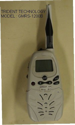
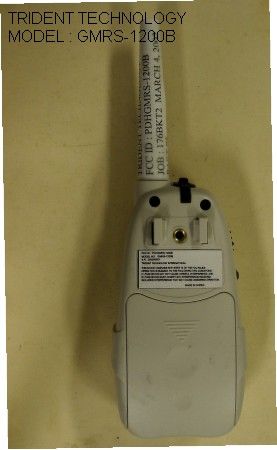
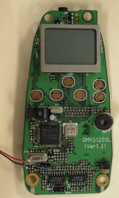
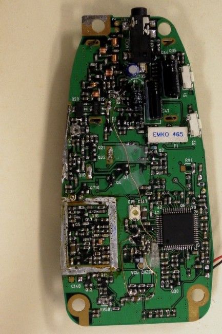
Applicant: TTI TECH CO., LTD. FCC ID: PDHGMRS-1200L Report #: T:\T\TTI_PDH\306KT2\306KT2TestReport.doc Page #: Table of Contents TABLE OF CONTENTS LIST APPLICANT: TTI TECH CO., LTD. FCC ID: PDHGMRS-1200L TEST REPORT: PAGE 1......COVER SHEET - GENERAL INFORMATION & TECHNICAL DESCR. PAGE 2......TECHNICAL DESCRIPTION CONTINUED & RF POWER OUTPUT PAGE 3......AUDIO FREQUENCY RESPONSE GRAPH PAGE 4......MODULATION LIMITING 300 Hz PAGE 5......MODULATION LIMITING 1000 Hz PAGE 6......MODULATION LIMITING 3000 Hz PAGE 7......AUDIO LOW PASS FILTER GRAPH PAGE 8......OCCUPIED BANDWIDTH PAGE 9-10...OCCUPIED BANDWIDTH PLOTS PAGE 11.....UNWANTED RADIATION – GMRS PAGE 12.....UNWANTED RADIATION - FRS PAGE 13.....METHOD OF MEASURING SPURIOUS EMISSIONS PAGE 14.....FREQUENCY STABILITY PAGE 15-18..LIST OF TEST EQUIPMENT EXHIBITS CONTAINING: EXHIBIT 1.........FCC ID LABEL SAMPLE EXHIBIT 2.........SKETCH OF LOCATION EXHIBIT 3.........EXTERNAL FRONT VIEW PHOTOGRAPH EXHIBIT 4.........EXTERNAL BACK VIEW PHOTOGRAPH EXHIBIT 5.........INTERNAL COMPONENT VIEW PHOTOGRAPH EXHIBIT 6.........INTERNAL COPPER VIEW PHOTOGRAPH EXHIBIT 7.........BLOCK DIAGRAM EXHIBIT 8.........SCHEMATIC EXHIBIT 9.........USERS MANUAL EXHIBIT 10........OPERATIONAL DESCRIPTION EXHIBIT 11........TUNING PROCEDURE EXHIBIT 12........TEST SET UP PHOTO Applicant: TTI TECH CO., LTD. FCC ID: PDHGMRS-1200L Report #: T:\T\TTI_PDH\306KT2\306KT2TestReport.doc Page #: 1 of 18 GENERAL INFORMATION REQUIRED FOR CERTIFICATION 2.1033(c)(1)(2) TTI TECH CO., LTD. will manufacture the FCCID: PDHGMRS-1200L GMRS CHANNELS TRANSCEIVER in quantity, for use under FCC RULES PART 95. TTI TECH CO., LTD. EUNDO BLDG. # 402, 737-19, BANPO-1DONG SEOCHO-KU 137-041 KOREA 2.1033 (c) TECHNICAL DESCRIPTION 2.1033(c)(3) Instruction book. A draft copy of the instruction manual is included as EXHIBIT 9. 2.1033(c) (4) Type of Emission: 10K0F3E 95.631 Bn = 2M + 2DK M = 3000 D = 2.0K Bn = 2(3.0)+2(2.0) = 10.0K Authorized Bandwidth 12.5 kHz 2.1033(c)(5) Frequency Range: 1. 462.5500 13. 462.7000 95.621 2. 462.5625 14. 462.7125 3. 462.5750 15. 462.7250 4. 462.5875 16. 467.5500 5. 462.6000 17. 467.5750 6. 462.6125 18. 467.6000 7. 462.6250 19. 467.6250 8. 462.6375 20. 467.6500 9. 462.6500 21. 467.6750 10. 462.6625 22. 467.7000 11. 462.6750 23. 467.7250 12. 462.6875 2.10311c)(6)(7) The Maximum Output Power Rating: GMRS High: 1.2 Watts ERP. Low: 0.5 Watts ERP. FRS 0.5 Watts effective radiated power. Applicant: TTI TECH CO., LTD. FCC ID: PDHGMRS-1200L Report #: T:\T\TTI_PDH\306KT2\306KT2TestReport.doc Page #: 2 of 18 2.1033(c)(8) DC Voltages and Current into Final Amplifier: FINAL AMPLIFIER ONLY FOR LOW POWER SETTING INPUT POWER: (6.0V)(.225A) = 1.35 Watts FOR HIGH POWER SETTING INPUT POWER: (6.0V)(.560A) =3.36 Watts 2.1033(c)(9) Tune-up procedure. The tune-up procedure is included 11. 2.1033(c)(10) Complete Circuit Diagrams: The circuit diagram is included as EXHIBIT 8 of this report. The block diagrams are included as EXHIBIT 7 of this report. 2.1033(c)(11) A photograph or a drawing of the equipment identification label is included as exhibit No. 1. 2.1033(c)(12) Photographs(8"X10") of the equipment of sufficient clarity to reveal equipment construction and layout, including meters, labels for controls, including any view under shields. See exhibits 3-6. 2.1033(c)(13) Digital modulation is not allowed. 2.1033(c)(14) The data required by 2.1046 through 2.1057 is submitted below. 95.639 Power Output shall not exceed 50.0 Watts effective radiated power. There can be no provisions for 95.649 increasing the power or varying the power. 2.1046(a) RF power (ERP) was measured by the substitution method and the ERP values are shown below. OUTPUT POWER: GMRS HIGH: 1.2 Watts ERP LOW: 0.5 Watts ERP FRS – 0.5 Watts ERP 2.1046(a) RF power output. The test procedure used was TIA/EIA-603 S2.2.1. Applican…
Text truncated - open the document above for the full version.
Contact Information
Applicant
J. N. LEE(Manager)
Technical Contact
Timco Engineering, Inc.Mario R de Aranzeta
[email protected]888-472-2424
849 N.W. State Road 45 · Newberry, Florida · United States
Non-Technical Contact
Timco Engineering, Inc.Sharon A Hoffman
[email protected]888-472-2424
Test Firm
Timco Engineering, Inc.S Sanders
Technical Specifications
| # | Rule Parts | Frequency Range | Power Output | Emission | Tolerance |
|---|---|---|---|---|---|
| 3 | 95B | 462.5625 MHz - 467.7125 MHz | 500.00 mW | 10K0F3E | 2.5 ppm |
Other Applications from TTI Tech Co., Ltd.
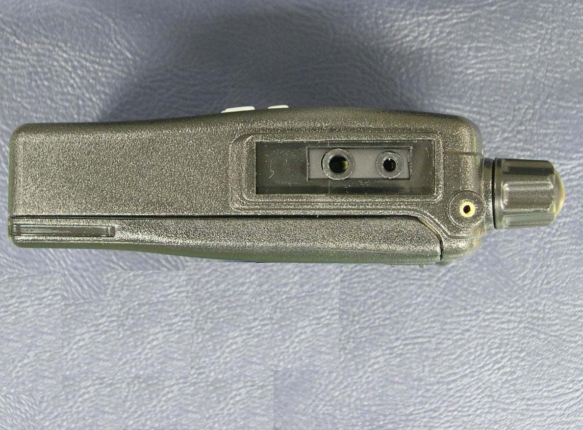
PDHTX150M
Jan 18, 2007HANDHELD MARINE RADIO
Equipment Class
TNF - Licensed Non-Broadcast Transmitter Held to Face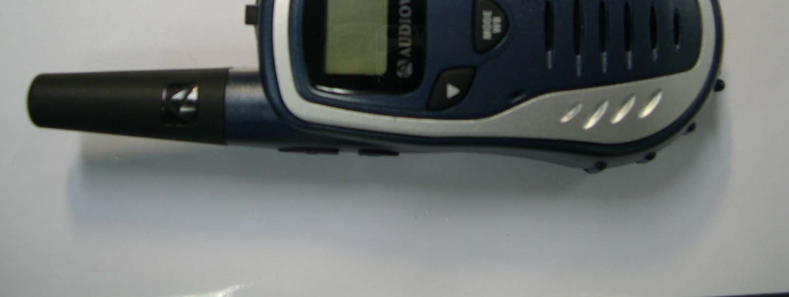
PDHGMRS200
Jul 05, 2005FRS/GMRS COMBINATION
Equipment Class
FRF - Part 95 Family Radio Face Held Transmitter
PDHGMRS1202
Feb 06, 2005FRS/ GMRS Combination
Equipment Class
FRF - Part 95 Family Radio Face Held Transmitter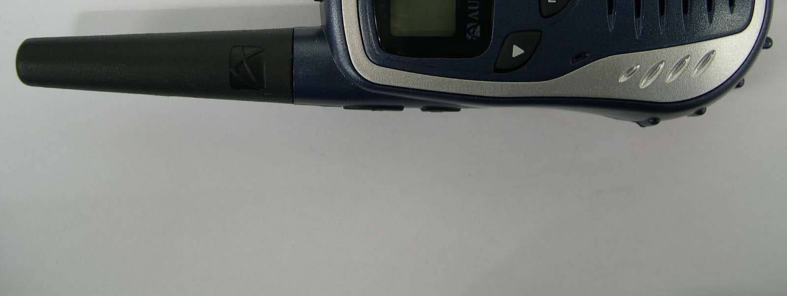
PDHGMRS602
Feb 06, 2005FRS/ GMRS Combination
Equipment Class
FRF - Part 95 Family Radio Face Held Transmitter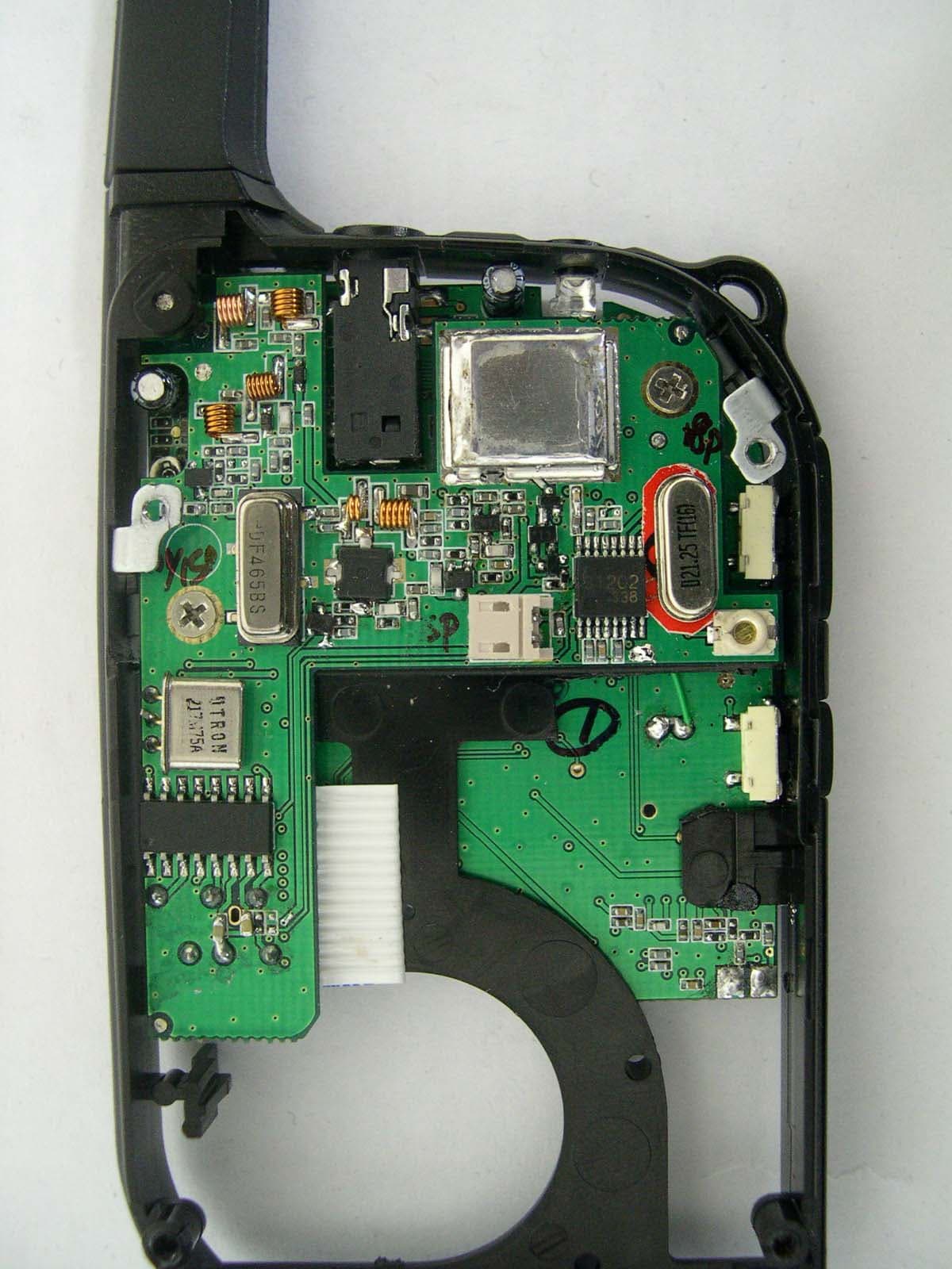
PDHGMRS500SLK
Apr 06, 2004GMRS/FRS Combination
Equipment Class
FRF - Part 95 Family Radio Face Held Transmitter