PDHGMRS-1545CHhandheld GMRS TX
TTI Tech Co., Ltd.
Click to zoom
Application Details
- Equipment Class
- TNF - Licensed Non-Broadcast Transmitter Held to Face
- Date of Grant
- Jul 02, 2001
- Application Purpose
- Original Equipment
- Date of Application
- Mar 29, 2001
- Equipment Note
- handheld GMRS TX
- Frequency Range
- 462.55000000 - 462.72500000
- Company
- TTI Tech Co., Ltd.
- Country
- South Korea
Documents & Files

Document Text
Text extracted from the exhibit documents filed with the FCC. Open a document above to read the original.
Users Manual
INDEX page 1. INTRODUCTION 1) Product Description3 2) Package Contents3 3) Features3 4) Front side Overview4 Instruction Manual * 38 CTCSS Sub Tone * Electronic Compass & Calibration mode * Vibrator Call * VOX mode * Scanning * Monitor * Key Pad Lock * Dual Watch * TX Power HI/LO * RSSI * Auto Power Save Mode * NOAA Weather Band (10CH) * Weather Alert * Battery Status Indicator * Emergency Channel * Back Light LCD Display * Choice of Battery - Rechargeable Battery - Standard Alkaline GMRS-1545 General Mobile Radio Service 462MHz,15CH 1 5) Rear side Overview5 6) Function and Feature Display 6 7) Mode (Function) key sequence - short press7 8) Mode (Weather ) key sequence - Long Press7 9) Electronic Compass Calibration7 2. INSTALLATION 1) Installation of the batteries7 2) Antenna7 3. BASIC OPRATION 1) On/Off & Volume control Switch8 2) Setting the Channel and tone code(CTCSS)8 3) VOX(Voice Operated Switching)8 4) Beep Tone8 5) Weather Alert9 6) Vibrator9 7) Setting the Transmit Power HI/LO9 8) Roger Tone9 9) Setting the DW(dual watch) 10 10) Call Ringer Selection Mode10 11) Transmitting10 12) Receiving10 13) Channel Scanning10 14) Emergency Channel11 15) Call11 16) Monitoring the channel11 17) Keypad Lock11 18) Backlight11 19) Battery status indicator12 20) External DC socket12 21) External Speaker/Mic12 4. Weather Radio 1) Weather Radio setting12 5. Calibrat the Electronic Compass12 6.Calibration mode13 7. INFORMATION 1) Radio13 2) Battery13 8. SPECIFICATIONS 13 9. MAIN CHANNEL FREQUENCY TABLE 13 10. CTCSS TONE CODE TABLE 14 11. WEATHER CHANNEL FREQUENCY TABLE 14 1. INTRODUCTION 1) Product Description GMRS-1545 General Mobile Radio Service has been designed to enable you to use for general purpose. This is a battery powered 462 MHz transceiver. The controls are easy to use and GMRS-1545 correspond to FRS for channel 1 to 7. Also it has a 38 CTCSS feature to get the clear communication without interference. GMRS-1545 has 10 NOAA weather channel and weather alert feature. GMRS-1545 is equipped with Electronic Compass and Vibrator Call feature. 2) Package Contents When you open the package,you should have; * GMRS-1545 Radio Unit 2 * Antenna * Wall charger * Rechargeable Battery ( AA x 5) * User’s Manual 3) Features * CTCSS(38 Frequency) * Electronic Compass * Calibration mode for Compass * Vibrator Call * VOX(Voice Operated Switching) * Scanning * Monitor * Keypad Lock * Dual Watch * TX Power HI/LO * AUto Squelch * RSSI(Received Signal Strength Indicator) * PSC(Auto Power Saving Control) * NOAA Weather Band(10CH) * Weather Alert * Battery Status Indicator * Emergency channel * LCD Back lighting * Transmitting LED * Call Signal (5 ringer signal) * Beep ON/OFF * Roger beep ON/OFF 4) Front side Overview 1 2 3 4 13 16 15 17 18 3 1External Speaker/Microphone Jack9Built-in Speaker (External Charger jack)10Desk top charger terminal 2Transmit LED indicator 11Channel & Volume DOWN button 3Liquid Crystal Display12Power ON/OFF button 4SCAN button13Emergency Channel button 5Monitopr/Lamp button14Battery Cover 6Channel & Volume UP button15Belt Clip 7Built-in Microphone16Push-To-Talk(PTT) button 8MODE button17Latch of belt clip 18Detachable Antenna 5) Rear side Overview 4 5 6 7 8 9 10 11 12 13 14 15 4 6) Function and Feature Display Battery indicator : Indicates the battery status. Receive signal indicator Monitor indicator Key lock indicator : Indicates that the key lock function is in Beep ON/OFF indicator : Indicates that the key tone is in use. Channel readout : Shows the current channel number CTCSS tone code number Weather Radio Indicator Emergency Channel indicator 5 7) Mode (Function) key sequence - short press * 1'st press -- Channel * 2'nd press -- CTCSS * 3’rd press -- VOX ON/OFF and sensitivity select * 4'th press -- Beep tone ON/OFF * 5'th press -- Weather Alert ON/OFF * 6’th press -- Vibrator ON/OFF select * 7'th press -- Tx power Hi / Low select * 8’th press -- Roger tone ON/OFF * 9’th press -- Dual watch channel select *10'th press -- Call Ringer setting 8) Mode (Weather ) key sequence - Long Press * 1’st press – Weather Channel select 9) Electronic Compass Calibration * While EMG button hold down,Power ON (2sec hold down) 2. INSTALLATION Your GMRS-1545 is designed to operate both in five "AA" size rechargeable battery (supplied) or Alkaline Batteries(not supplied). Cautions Never attempt to charge Alkaline or Dry Cell Batteries. When recharging the rechargeable batteries, use only recommended one.Use of other batteries will cause demage to your GMRS-1545 transceiver. Other type of batteries may burst causing personal injury. 1) Installation of the batteries * Ensure that the GMRS-1545 sets to power off. * Hold the radio and battery cover with the back facing you. * Press and slide the battery cover. Scan indicator : Indicates that scan is CTCSS indicator: Indicates that the CTCSS function is in use. VOX (Voice Activated Transmit) Indicator Roger ON/OFF indicator : Indicates that the key tone is in use. CTC HI SCAN DW LO VOX TX power High setting Indicator Dual Watch enable Indicator TX power Low setting Indicator VIB Electronic Compass Indicator Vibrator Call Indicator 6 * Install five "AA" size Alkaline batteries or rechargeable batteries. Note : Carefully observe the polarity of the batteries before installing. * Replace the cover. 2) Antenna The antenna is detachable type.You can replace it to external antenna. Keep the Antenna at 1inch away from your head and body. 3. Basic Operation 1) On/Off & Volume control Switch Radio ON : Press the power button at least for 2 seconds.You will hear confirming melody to indicated the unit is on. Radio Off : Press the power button at least for 2 seconds. Volume setting : Press up[ ] or down[ ] button to adjust a level that is most comfortable for you while monitor is active. 2) Setting the Channel and tone code(CTCSS) GMRS-1545 has 15 main channels and 38 sub-channels. * 15 Frequency channels * 38 CTCSS Code ( indicated by CTC icon on the LCD ) To s…
Text truncated - open the document above for the full version.
Cover Letter(s)
TIMCO ENGINEERING, INC. P.O. BOX 370 849 N.W. STATE ROAD 45 NEWBERRY, FL 32669 PHONE: 888-472-2424 OR 352-472-5500 FAX: 352-472-2030 EMAIL: [email protected] 6/15/01 Mr. Joe Dichoso Federal Communications Commission Authorization and Evaluation Division 7435 Oakland Mills Road Columbia, MD 21046 Ref: Trident Technology International’s FCC ID: PDHGMRS-1545CH, Confirmation # EA100508, Your Correspondence ID 19352 Dear Joe: I have uploaded a revised test report with corrections made. The pages that have been changed are Page 1, 3, 4, 5. There were some errors in the report. Per your request of 5/21/01; 1. Please correct the 731 form to read 9K8F3E which is the correct emission designator. I’ve also corrected Page 1 of the test report to reflect this change. 2. I’ve uploaded better internal photographs. 3. This device is a GMRS device. The correct frequency range on the report (Page 1) and on the 731 form should be: 462.550-462.7250 MHz. I’ve corrected Page 1 of the report. Please correct the 731 form. 4a. The tuneup procedure is correct. The 731 form was in error. The correct output power is 2.0 Watts (High) and 0.5 Watts (Low). On the page that you read 4.43 and 1.5 as the listed ERP (Page 1) – that is actually the dc input power, not the output power. 4b. The conducted output power is 2.0 Watts (High), 0.5 Watts (Low). Please refer to page 4 of the corrected test report. Please correct the 731 form. 4c. The antenna has negative gain. 4d. The ERP is 2.0 Watts (High), 0.5 Watts (Low) 4e. The field strength level of the fundamental is: 130.44 dBuV/m (High) 124.94 dBuV/m (Low) 5. They have included statements in their manual (please refer to Page 7) regarding the distance between the user and the antenna. Should you have any further questions, please advise. Regards, Sharon A. Hoffman TIMCO ENGINEERING, INC.
Cover Letter(s)
TIMCO ENGINEERING, INC. P.O. BOX 370 849 N.W. STATE ROAD 45 NEWBERRY, FL 32669 PHONE: 888-472-2424 OR 352-472-5500 FAX: 352-472-2030 EMAIL: [email protected] 6/27/01 Mr. Joe Dichoso Federal Communications Commission Authorization and Evaluation Division 7435 Oakland Mills Road Columbia, MD 21046 Ref: Trident Technology International’s FCC ID: PDHGMRS-1545CH, Confirmation # EA100508, Your Correspondence ID 19678 Dear Joe: Per your request of 6/19/01; 1. The conducted output power and the ERP are the same because the antenna gain is 0 db. 2. We have done the calculation for SAR and I have attached that calculation for our review. Should you have any further questions,please advise. Regards, Sharon A. Hoffman TIMCO ENGINEERING, INC.
Test Report
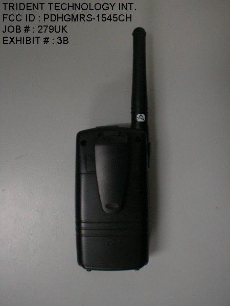
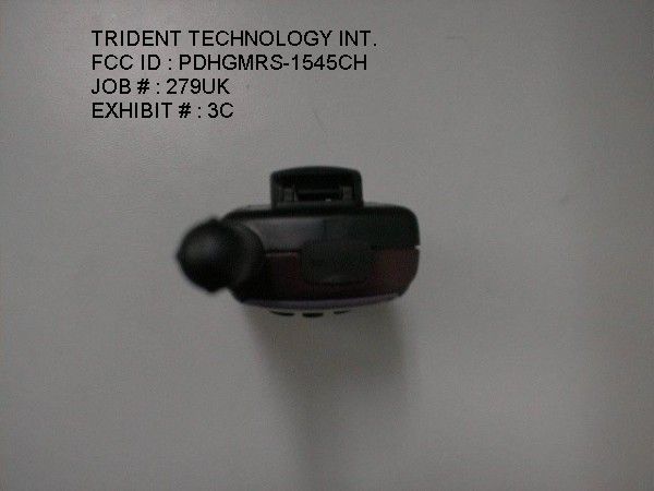
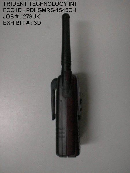
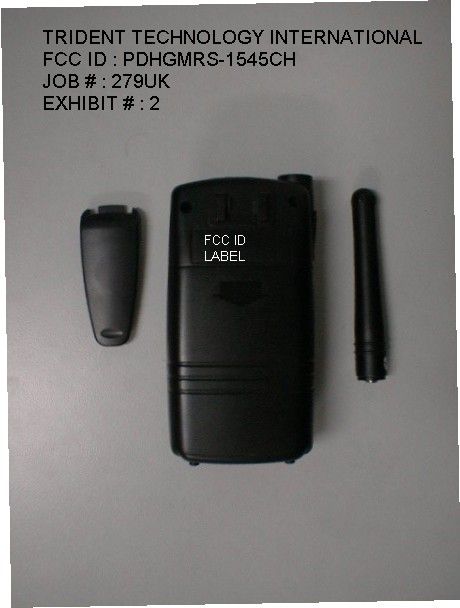
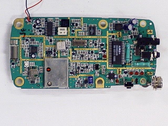
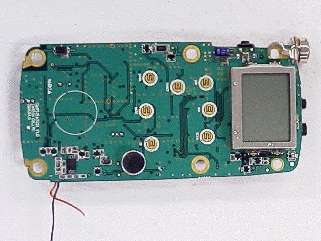
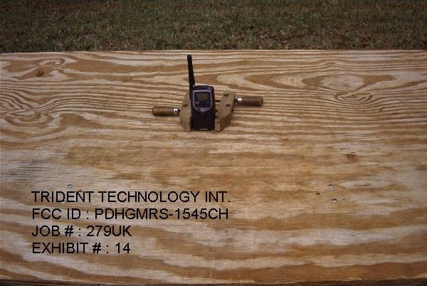
TABLE OF CONTENTS LIST APPLICANT: TRIDENT TECHNOLOGY INTERNATIONAL FCC ID: PDHGMRS-1545CH TEST REPORT: PAGE 1......COVER SHEET - GENERAL INFORMATION & TECHNICAL DESCR. PAGE 2......TECHNICAL DESCRIPTION CONTINUED & RF POWER OUTPUT PAGE 3......MODULATION CHARACTERISTICS & OCCUPIED BANDWIDTH PAGE 4......SPURIOUS EMISSIONS AT ANTENNA TERMINALS PAGE 5......UNWANTED RADIATION PAGE 6......METHOD OF MEASURING SPURIOUS EMISSIONS PAGE 7......FREQUENCY STABILITY PAGE 8......LIST OF TEST EQUIPMENT EXHIBITS CONTAINING: EXHIBIT 1.........FCC ID LABEL SAMPLE EXHIBIT 2.........SKETCH OF FCC ID LABEL LOCATION EXHIBIT 3A........EXTERNAL PHOTO – FRONT VIEW EXHIBIT 3B........EXTERNAL PHOTO – REAR VIEW EXHIBIT 3C........EXTERNAL PHOTO – TOP VIEW EXHIBIT 3D......................EXTERNAL PHOTO – SIDE VIEW EXHIBIT 3E......................INTERNAL PHOTO – COMPONENT VIEW EXHIBIT 3F......................INTERNAL PHOTO – COPPER VIEW EXHIBIT 4.........BLOCK DIAGRAM EXHIBIT 5A-5B.....SCHEMATICS EXHIBIT 6.........USER'S MANUAL EXHIBIT 7.........THEORY OF OPERATION EXHIBIT 8.........TUNING PROCEDURE EXHIBIT 9.........AUDIO LOW PASS FILTER EXHIBIT 10A.......MODULATION LIMITING 300 Hz EXHIBIT 10B.......MODULATION LIMITING 1000 Hz EXHIBIT 10C.......MODULATION LIMITING 3000 Hz EXHIBIT 11........AUDIO FREQUENCY RESPONSE GRAPH EXHIBIT 12........OCCUPIED BANDWIDTH CW PLOT EXHIBIT 13........OCCUPIED BANDWIDTH EXHIBIT 14........TEST SET UP PHOTO APPLICANT: TRIDENT TECHNOLOGY INTERNATIONAL FCC ID: PDHGMRS-1545CH DATE: MARCH 23, 2001 REPORT #: T:\CUS\T\TRIDENT\279UK1\279UK1RPT.DOC PAGE: TABLE OF CONTENTS GENERAL INFORMATION REQUIRED FOR CERTIFICATION 2.1033(c)(1)(2) TRIDENT TECHNOLOGY INTERNATIONAL will manufacture the FCCID: PDHGMRS-1545CH GMRS CHANNELS TRANSCEIVER in quantity, for use under FCC RULES PART 95. TRIDENT TECHNOLOGY INTERNATIONAL 100 THROCKMORTON STREET SUITE 1300 FT. WORTH, TX 76102-2802 2.1033 (c) TECHNICAL DESCRIPTION 2.1033(c)(3) Instruction book. A draft copy of the instruction manual is included as EXHIBIT 6. 2.1033(c) (4) Type of Emission: 9K8F3E 95.629 Bn = 2M + 2DK M = 3000 D = 1.75K Bn = 2(3.0)+2(1.90) = 9.8K Authorized Bandwidth 20.0KHz 2.1033(c)(5) Frequency Range: 462.5625 - 462.7250 MHz 95.627 2.10311c)(6)(7) The Maximum Output Power Rating: High: 1.5 Watts Low: 1.0 Watts effective radiated power. 2.1033(c)(8) DC Voltages and Current into Final Amplifier: FINAL AMPLIFIER ONLY FOR LOW POWER SETTING INPUT POWER: (7.5V)(.24A) = 1.8 Watts FOR HIGH POWER SETTING INPUT POWER:(7.5V)(.59A) = 4.43 Watts 2.1033(c)(9) Tune-up procedure. The tune-up procedure is included 8. APPLICANT: TRIDENT TECHNOLOGY INTERNATIONAL FCC ID: PDHGMRS-1545CH DATE: MARCH 23, 2001 REPORT #: T:\CUS\T\TRIDENT\279UK1\279UK1RPT.DOC PAGE #: 1 2.1033(c)(10) Complete Circuit Diagrams: The circuit diagram is included as EXHIBIT 5 of this report. The block diagrams are included as EXHIBIT 4 of this report. 2.1033(c)(11) A photograph or a drawing of the equipment identification label is included as exhibit No. 1. 2.1033(c)(12) Photographs(8" X 10") of the equipment of sufficient clarity to reveal equipment construction and layout, including meters, labels for controls, including any view under shields. See exhibits 2-3. 2.1033(c)(13) Digital modulation is not allowed. 2.1033(c)(14) The data required by 2.1046 through 2.1057 is submitted below. 95.639 Power Output shall not exceed 50.0 Watts effective radiated power. There can be no provisions for 95.649 increasing the power or varying the power.RF power output. 2.1046(a) RF power is measured by connecting a 50 ohm, resistive watt meter to the RF output connector. With a nominal battery voltage of 7.5 V, and the transmitter properly adjusted the RF output measures: OUTPUT POWER: HIGH: 1.5 Watts LOW: 1.0 Watt 2.1046(a) RF power output. The test procedure used was TIA/EIA-603 S2.2.1. APPLICANT: TRIDENT TECHNOLOGY INTERNATIONAL FCC ID: PDHGMRS-1545CH DATE: MARCH 23, 2001 REPORT #: T:\CUS\T\TRIDENT\279UK1\279UK1RPT.DOC PAGE #: 2 2.1047(a)(b) Modulation characteristics: AUDIO FREQUENCY RESPONSE The audio frequency response was measured in ac- cordance with TIA/EIA Specification 603. The audio frequency response curve is shown on the next page. The audio signal was fed into a dummy microphone circuit and into the microphone connector. The input required to produce 30 percent modulation level was measured. See Exhibit 11. 2.1047(b) Audio input versus modulation The audio input level needed for a particular per- percentage of modulation was measured in accor- dance with TIA/EIA Specification 603. The audio input curves versus modulation are on the following pages. Curves are provided for audio input frequen- cies of 300, 1000, and 3000 Hz. See Exhibits 10A-10C. 95.637 Post Limiter Filter Each GMRS transmitter, except a mobile station transmitter with a power of 2.5Watts or less, must be equipped with an audio low pass filter. At any frequency between 3 & 20KHz the filter must have an attenuation of 60log (f/3) greater than the attenuation at 1KHz. See Exhibit 9. 2.1049 Occupied bandwidth: 95.635(b)(1)(3)(7) At least 25dB on any frequency removed from the center of the authorized bandwidth by more than 50%up to and including 100% of the authorized bandwidth. At least 35 dB on any frequency removed from the center of the authorized BW by more than 100% up to and including 250% of the authorized BW. At least 43+log10(T) on any frequency removed from the center of the authorized bandwidth by more than 250%. REPORT #: T:\CUS\T\TRIDENT\279UK1\279UK1RPT.DOC PAGE #: 3 2.1051 Spurious emissions at antenna terminals(conducted): The following data shows the level of conducted spurious responses at the antenna terminal. The test procedure used was TIA/EIA 603 S2.2.13 with the exception that the emissions were recorded in dBc. The spectrum was scanned from 0.4 to at least the 10th harmonic of the fundamental. Method of Measuring Conducted Spurious Emissions 2.1051 Spurious emissions at the Antenna Terminals NAME OF …
Text truncated - open the document above for the full version.
Test Report
TABLE OF CONTENTS LIST APPLICANT: TRIDENT TECHNOLOGY INTERNATIONAL FCC ID: PDHGMRS-1545CH TEST REPORT: PAGE 1......COVER SHEET - GENERAL INFORMATION & TECHNICAL DESCR. PAGE 2......TECHNICAL DESCRIPTION CONTINUED & RF POWER OUTPUT PAGE 3......MODULATION CHARACTERISTICS & OCCUPIED BANDWIDTH PAGE 4......SPURIOUS EMISSIONS AT ANTENNA TERMINALS PAGE 5......UNWANTED RADIATION PAGE 6......METHOD OF MEASURING SPURIOUS EMISSIONS PAGE 7......FREQUENCY STABILITY PAGE 8......LIST OF TEST EQUIPMENT EXHIBITS CONTAINING: EXHIBIT 1.........FCC ID LABEL SAMPLE EXHIBIT 2.........SKETCH OF FCC ID LABEL LOCATION EXHIBIT 3A........EXTERNAL PHOTO – FRONT VIEW EXHIBIT 3B........EXTERNAL PHOTO – REAR VIEW EXHIBIT 3C........EXTERNAL PHOTO – TOP VIEW EXHIBIT 3D......................EXTERNAL PHOTO – SIDE VIEW EXHIBIT 3E......................INTERNAL PHOTO – COMPONENT VIEW EXHIBIT 3F......................INTERNAL PHOTO – COPPER VIEW EXHIBIT 4.........BLOCK DIAGRAM EXHIBIT 5A-5B.....SCHEMATICS EXHIBIT 6.........USER'S MANUAL EXHIBIT 7.........THEORY OF OPERATION EXHIBIT 8.........TUNING PROCEDURE EXHIBIT 9.........AUDIO LOW PASS FILTER EXHIBIT 10A.......MODULATION LIMITING 300 Hz EXHIBIT 10B.......MODULATION LIMITING 1000 Hz EXHIBIT 10C.......MODULATION LIMITING 3000 Hz EXHIBIT 11........AUDIO FREQUENCY RESPONSE GRAPH EXHIBIT 12........OCCUPIED BANDWIDTH CW PLOT EXHIBIT 13........OCCUPIED BANDWIDTH EXHIBIT 14........TEST SET UP PHOTO APPLICANT: TRIDENT TECHNOLOGY INTERNATIONAL FCC ID: PDHGMRS-1545CH DATE: MARCH 23, 2001 REPORT #: T:\CUS\T\TRIDENT\279UK1\279UK1RPT.DOC PAGE: TABLE OF CONTENTS GENERAL INFORMATION REQUIRED FOR CERTIFICATION 2.1033(c)(1)(2) TRIDENT TECHNOLOGY INTERNATIONAL will manufacture the FCCID: PDHGMRS-1545CH GMRS CHANNELS TRANSCEIVER in quantity, for use under FCC RULES PART 95. TRIDENT TECHNOLOGY INTERNATIONAL 100 THROCKMORTON STREET SUITE 1300 FT. WORTH, TX 76102-2802 2.1033 (c) TECHNICAL DESCRIPTION 2.1033(c)(3) Instruction book. A draft copy of the instruction manual is included as EXHIBIT 6. 2.1033(c) (4) Type of Emission: 9K8F3E 95.629 Bn = 2M + 2DK M = 3000 D = 1.9K Bn = 2(3.0)+2(1.90) = 9.8K Authorized Bandwidth 20.0KHz 2.1033(c)(5) Frequency Range: 462.5500 - 462.7250 MHz 95.627 2.10311c)(6)(7) The Maximum Output Power Rating: High: 2.0 Watts Low: 0.5 Watts effective radiated power. 2.1033(c)(8) DC Voltages and Current into Final Amplifier: FINAL AMPLIFIER ONLY FOR LOW POWER SETTING INPUT POWER: (7.5V)(.24A) = 1.8 Watts FOR HIGH POWER SETTING INPUT POWER:(7.5V)(.59A) = 4.43 Watts 2.1033(c)(9) Tune-up procedure. The tune-up procedure is included 8. APPLICANT: TRIDENT TECHNOLOGY INTERNATIONAL FCC ID: PDHGMRS-1545CH DATE: MARCH 23, 2001 REPORT #: T:\CUS\T\TRIDENT\279UK1\279UK1RPT.DOC PAGE #: 1 2.1033(c)(10) Complete Circuit Diagrams: The circuit diagram is included as EXHIBIT 5 of this report. The block diagrams are included as EXHIBIT 4 of this report. 2.1033(c)(11) A photograph or a drawing of the equipment identification label is included as exhibit No. 1. 2.1033(c)(12) Photographs(8" X 10") of the equipment of sufficient clarity to reveal equipment construction and layout, including meters, labels for controls, including any view under shields. See exhibits 2-3. 2.1033(c)(13) Digital modulation is not allowed. 2.1033(c)(14) The data required by 2.1046 through 2.1057 is submitted below. 95.639 Power Output shall not exceed 50.0 Watts effective radiated power. There can be no provisions for 95.649 increasing the power or varying the power.RF power output. 2.1046(a) RF power is measured by connecting a 50 ohm, resistive watt meter to the RF output connector. With a nominal battery voltage of 7.5 V, and the transmitter properly adjusted the RF output measures: OUTPUT POWER: HIGH: 2.0 Watts LOW: 0.5 Watt 2.1046(a) RF power output. The test procedure used was TIA/EIA-603 S2.2.1. APPLICANT: TRIDENT TECHNOLOGY INTERNATIONAL FCC ID: PDHGMRS-1545CH DATE: MARCH 23, 2001 REPORT #: T:\CUS\T\TRIDENT\279UK1\279UK1RPT.DOC PAGE #: 2 2.1047(a)(b) Modulation characteristics: AUDIO FREQUENCY RESPONSE The audio frequency response was measured in ac- cordance with TIA/EIA Specification 603. The audio frequency response curve is shown on the next page. The audio signal was fed into a dummy microphone circuit and into the microphone connector. The input required to produce 30 percent modulation level was measured. See Exhibit 11. 2.1047(b) Audio input versus modulation The audio input level needed for a particular per- percentage of modulation was measured in accor- dance with TIA/EIA Specification 603. The audio input curves versus modulation are on the following pages. Curves are provided for audio input frequen- cies of 300, 1000, and 3000 Hz. See Exhibits 10A-10C. 95.637 Post Limiter Filter Each GMRS transmitter, except a mobile station transmitter with a power of 2.5Watts or less, must be equipped with an audio low pass filter. At any frequency between 3 & 20KHz the filter must have an attenuation of 60log (f/3) greater than the attenuation at 1KHz. See Exhibit 9. 2.1049 Occupied bandwidth: 95.635(b)(1)(3)(7) At least 25dB on any frequency removed from the center of the authorized bandwidth by more than 50%up to and including 100% of the authorized bandwidth. At least 35 dB on any frequency removed from the center of the authorized BW by more than 100% up to and including 250% of the authorized BW. At least 43+log10(T) on any frequency removed from the center of the authorized bandwidth by more than 250%. REPORT #: T:\CUS\T\TRIDENT\279UK1\279UK1RPT.DOC PAGE #: 3 2.1051 Spurious emissions at antenna terminals(conducted): The following data shows the level of conducted spurious responses at the antenna terminal. The test procedure used was TIA/EIA 603 S2.2.13 with the exception that the emissions were recorded in dBc. The spectrum was scanned from 0.4 to at least the 10th harmonic of the fundamental. Method of Measuring Conducted Spurious Emissions 2.1051 Spurious emissions at the Antenna Terminals NAME OF T…
Text truncated - open the document above for the full version.
Contact Information
Applicant
J. N. LEE(Manager)
Technical Contact
Timco Engineering, Inc.Mario de Aranzeta
[email protected]888-472-2424
P.O. Box 370 · Newberry, Florida · United States
Non-Technical Contact
Timco Engineering, Inc.Mario de Aranzeta
[email protected]888-472-2424
Test Firm
Timco Engineering, Inc.S Sanders
Technical Specifications
| # | Rule Parts | Frequency Range | Power Output | Emission | Tolerance |
|---|---|---|---|---|---|
| 2 | 95A | 462.55 MHz - 462.725 MHz | 500.00 mW | 9K80F3E | 0.0005 % |
Other Applications from TTI Tech Co., Ltd.
PDHTX150M
Jan 18, 2007HANDHELD MARINE RADIO
Equipment Class
TNF - Licensed Non-Broadcast Transmitter Held to Face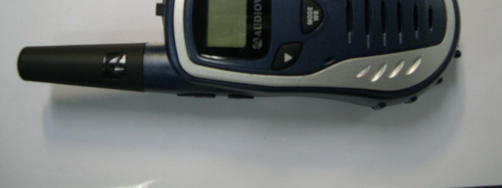
PDHGMRS200
Jul 05, 2005FRS/GMRS COMBINATION
Equipment Class
FRF - Part 95 Family Radio Face Held Transmitter
PDHGMRS1202
Feb 06, 2005FRS/ GMRS Combination
Equipment Class
FRF - Part 95 Family Radio Face Held Transmitter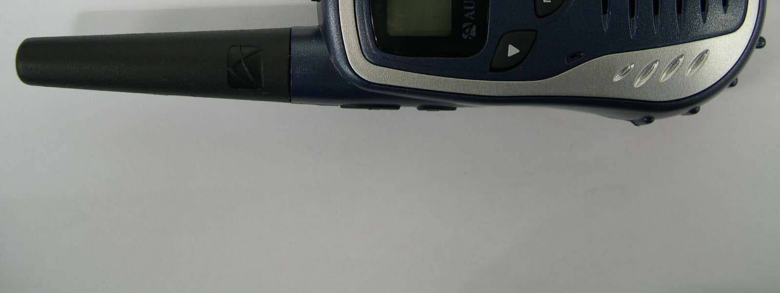
PDHGMRS602
Feb 06, 2005FRS/ GMRS Combination
Equipment Class
FRF - Part 95 Family Radio Face Held Transmitter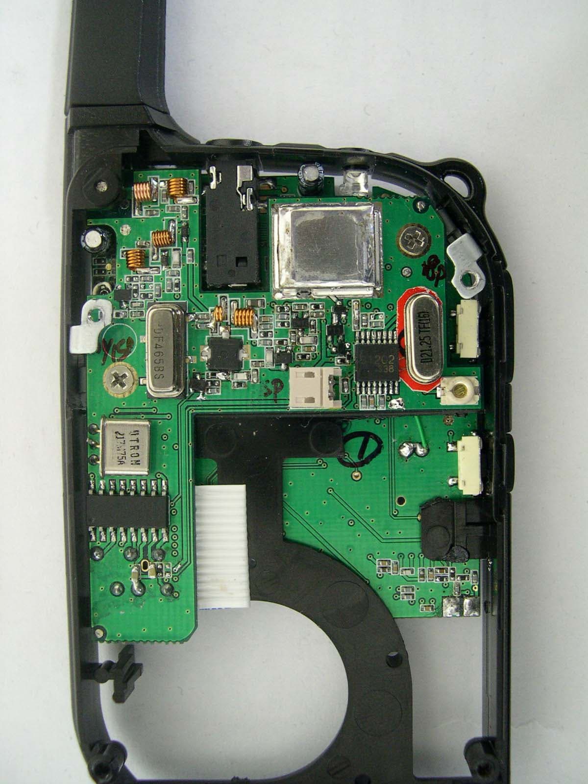
PDHGMRS500SLK
Apr 06, 2004GMRS/FRS Combination
Equipment Class
FRF - Part 95 Family Radio Face Held Transmitter