PE3DOYAK-RWIRELESS PEN MOUSE RECEIVER
ISV Co., Ltd.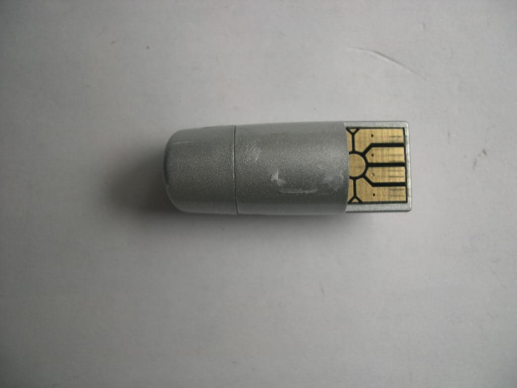
Click to zoom
Application Details
- Equipment Class
- DXX - Part 15 Low Power Communication Device Transmitter
- Date of Grant
- Oct 15, 2007
- Application Purpose
- Original Equipment
- Date of Application
- Oct 11, 2007
- Equipment Note
- WIRELESS PEN MOUSE RECEIVER
- Frequency Range
- 2403.00000000 - 2480.00000000
- Company
- ISV Co., Ltd.
- Country
- South Korea
Documents & Files
Document Text
Text extracted from the exhibit documents filed with the FCC. Open a document above to read the original.
Users Manual
Configuring Windows XP before Usage Important Safety Instructions When using your pen mouse equipment, basic safety precautions should always be followed to reduce the risk of fire, electric shock, and injury to persons, including the following: 1.Read and understand all instructions. 2.Do not use liquid cleaners or aerosol cleaners. Use a damp cloth for cleaning. 3. Do not use this product near water, for example, near a bathtub, washbowl, kitchen sink, or laundry tub, in a wet basement or near a swimming pool. 4.Do not place this product on an unstable cart, stand, or table. The product may fall, causing serious damag e to the product. 5. To reduce the risk of electric shock, do not disassemble this product, but take it to a qualified service contra ctor when some service or repair work is required. Opening or removing covers may expose you to dangero us voltages or other risks. Incorrect reassembly can cause electric shock when the appliance is subsequentl y used. 7.Unplug this product from the power source and refer servicing to qualified service personnel under the foll owing conditions: A. If liquid has been spilled into the product. •If the product has been exposed to rain or water. D. If the product does not operate normally by following the operating instructions, Adjust only those controls that are covered by the operating instructions. Improper E. Adjustments of other controls may result in damage and will often require extensive work by a qualified tec hnician to restore the product to normal operation. F. If the product has been dropped or the cabinet has been damaged. G. If the product exhibits a distinctive change in performance. THIS DEVICE COMPLIES WITH PART 15 OF THE FCC RULES. OPERATION IS SUBJECT TO THE FOLLOWING TWO CONDITIONS: (1) THIS DEVICE MAY NOT CAUSE HARMFUL INTERFERENCE, AND (2) THIS DEVICE MUST ACCEPT ANY INTERFERENCE RECEIVED, INCLUDING INTERFERENCE THAT MAY CAUSE UNDERSIRED OPERATION. FCC Notice This equipment has been tested and found to comply with the limits for a Class B digital device, pursuant to part 15 of the FCC Rules. These limits are designed to provide reasonable protection against harmful interference in a residential installation. This equipment generates, uses and can radiate radio frequency energy and, if not installed and used in accordance with the instructions, may cause harmful interference to radio communication. However, there is no guarantee that interference will not occur in a particular installation. If this equipment does cause harmful interference to radio or television reception, which can be determined by turning the equipment off and on, the user is encouraged to try to correct the interference by one or more of the following measures : - Reorient or relocate the receiving antenna. - Increase the separation between the equipment and receiver. - Connect the equipment into an outlet on a circuit difference from that to which the receiver is connected. - Consult the dealer of an experienced radio/TV technician for help. NOTE : The manufacturer is not responsible for any radio or TV interference caused by unauthorized modifications to this equipment. Such modifications could void the user's authority to operate the equipment. NEW PEN and MOUSE Operating Guide. Holding Pen and mouseInstallation of Receiver Docking Pen and mouse 1. Plug Receiver into USB Port with Computer 2. If Receiver is possible to use your computer, Receiver’s LED is flashing one time. 3. Press LED light button (See Page 5) Check that LED is turn on IF LED is not on, your Receiver is reverse plugged Battery indicator Low battery : Pen’s Led is Flashing While charging : Pen’s Led is on Full charge : Pen’s Led is off When Pen and Receiver is docked, Automatically power is off. To restart pen and memory mode, Press power button (See page 5) over 3 seconds Power Save 1. Goes power down mode without any action during 30 second. 2. When Pen is docked with Receiver, goes in to power down 3. Press and Hold ①button (see page5) over 3Second, goes in to power down Configuring Windows XP before Usage You can use Pen&Mouse as a natural pen, such as drawing a graph or write a text and sign. When Pen mode is selected, you can feel more comfortable and precisely drawing or writing by changing of setting of control panel. (This setting is only used in Windows XP version.) 1. Press STARTbutton →select control panel→select Printers and other Hardware →select mouse 2. It will appear on your mouse propertiesand select pointer optionstab You will see the “Enhance pointer precision”option. Please cancel the checked indication to use more comfortable using the Pen and mouse You can use penandmouse as a “Mouse” setting the acceleration faster on a mouse mode. you can adjust the acceleration to which you feel most comfortable with. NEW PEN and MOUSE Quick Guide 1 Power ON Press ①button to re-power on over 3 seconds ① Pen&Mouse Mode Power Off/On Key ② Scroll center Right Button Pen and Left Button Scroll <Wheel> Button ③ Memory Pen mode : Press the Button over 3 second Text size & Point size adjustment Laser Pointer button LED light button <Flash Lantern> DC Jack IN <Charging> RECEIVER Registration 1. Press ①and ②button at a time, Pen’s LED is flashing continuously 2. Press Receiver’s LED light button, Receiver’s LED is flashing one time. 1. Pen and Mouse Usage 1-1 Separate Receiver and Pen 1-2 Plug Receiver into USB Port with Computer 1-3 If Receiver is possible to use your computer, Receiver’s LED flashing one time 2. Memory pen Mode Usage Enter Memory mode. 2-1 Press and hold ④button over 3second The pen’s LED is flashing each 1 second 2-2 Press ②button, The LED is more fast flashing 2-3 write a text or drawing you want (Tip : more convenient write during open paint Program) 2-4 press ②button to Save the data The pen’s LED is flashing each 1 second again Play memorized data 2-5 Plug Receiver into USB Port with Computer 2-6 Press ①button to play data which was LAST memorized 2-7 Press…
Text truncated - open the document above for the full version.
Cover Letter(s)
October 8, 2007 Federal Communications Commission Authorization and Evaluation Division Confidentiality Request regarding application for certification of FCC ID: PE3DOYAK-R Pursuant to Sections 0.457 and 0.459 of the Commission’s Rules, we hereby request confidential treatment of information accompanying this application as outlined below: Exhibit Type File Name Technical Description PE3DOYAK-R Technical Description.pdf Schematics Diagram(s) PE3DOYAK-R SCHEMATIC.pdf Block Diagram PE3DOYAK-R Block Diagram.pdf The above materials contain trade secrets and proprietary information not customarily released to the public. The public disclosure of these materials may be harmful to the applicant and provide unjustified benefits to its competitors. The applicant understands that pursuant to Section 0.457 of the Rules, disclosure of this application and all accompanying documentation will not be made before the date of the Grant for this application. Sincerely,
Parts List/Tune Up Info
ITEM SPEC SIZE DESCRIPTION TOL. REFERENCE NUMBER UNIT Q'TY MANUFACTURE R AGENT U/PRICE AMOUNT ATTN. TEL RX DIP TYPEPCB FR-4 DOYAK 5 RX 1.0T (BLACK, GOLD) EA 1 SEWON ANT WRAPPING WIRE WRAPPING 30mm_STRIP1mm,BLUE ANT EA 1 DONGSEO DC JACK DIP DC064D-3 J100 EA 1 GANA LED FLASH LAMP 514UWC-TB LED100 EA 1 KOREA BRIGHT CABLE ROLL TYPE JS-003006 DC2.5 to DC2.5 800mm, White EA 1 GANA RX SMD TYPEIC MCU OPT CY7C63743CQ-13 U101 EA 1 CYPRESS ARROW IC RF NRF24L01 U102 EA 1 NORDIC AVNET IC LDO NJM2877F3-03-TE1 U103 EA 1 JRC JINTECH IC LDO NJM2877F3-42-TE1 U104 EA 1 JRC JINTECH IC VOLTAGE DETECT NJU7700F4-39-TE1 U105 EA 1 JRC JINTECH IC EEPROM CAT24WC02 U100 EA 1 CATALYST SHINYOUNG X-TAL SMD 2*3 AR16011203 16MHz 30PPM X100 EA 1 SUNNY JEIL SWITCH SKRELJE010 SW101 EA 1 ALPS HANNUNG RES CHIP 2012 7R5 1/4W J R1 EA 1 SAMSUNG YOUSUNG RES CHIP 1005 390 1/16W J R116,R117 EA 2 SAMSUNG YOUSUNG RES CHIP 1005 101 1/16W J R120 EA 1 SAMSUNG YOUSUNG RES CHIP 1005 102 1/16W J R100 EA 1 SAMSUNG YOUSUNG RES CHIP 1005 152 1/16W J R118 EA 1 SAMSUNG YOUSUNG RES CHIP 1005 332 1/16W J R107,R108,R109,R110,R112,R113 EA 6 SAMSUNG YOU SUNG RES CHIP 1005 103 1/16W J R105 EA 1 SAMSUNG YOUSUNG RES CHIP 1005 223 1/16W J R115 EA 1 SAMSUNG YOUSUNG RES CHIP 1005 154 1/16W J R103 EA 1 SAMSUNG YOUSUNG RES CHIP 1005 274 1/16W J R101,R102 EA 2 SAMSUNG YOUSUNG RES CHIP 1005 474 1/16W J R104 EA 1 SAMSUNG YOUSUNG RES CHIP 1005 105 1/16W J R114 EA 1 SAMSUNG YOUSUNG CAP CHIP 1005 1R5 25V C C105 EA 1 MURATA ASUNG TECHNO CAP CHIP 1005 4R7 25V C C108 EA 1 MURATA ASUNG TECHNO CAP CHIP 1005 180 25V K C101 EA 1 MURATA ASUNG TECHNO CAP CHIP 1005 240 25V K C100 EA 1 MURATA ASUNG TECHNO CAP CHIP 1005 222 25V K C107 EA 1 MURATA ASUNG TECHNO CAP CHIP 1005 103 25V K C109,C111 EA 2 MURATA ASUNG TECHNO CAP CHIP 1005 333 25V K C104 EA 1 MURATA ASUNG TECHNO MODEL DOYAK INTERNATIONAL SCIENCE VENTURE SUB LOCATION RX DOCUMENT NUMBER P A R T S L I S T P A R T S L I S T P A R T S L I S T P A R T S L I S T P A R T S L I S T P A R T S L I S T P A R T S L I S T P A R T S L I S T P A R T S L I S T P A R T S L I S T P A R T S L I S T P A R T S L I S T P A R T S L I S T P A R T S L I S T P A R T S L I S T P A R T S L I S T P A R T S L I S T P A R T S L I S T P A R T S L I S T P A R T S L I S T P A R T S L I S T P A R T S L I S T P A R T S L I S T P A R T S L I S T P A R T S L I S T P A R T S L I S T P A R T S L I S T P A R T S L I S T P A R T S L I S T P A R T S L I S T P A R T S L I S T P A R T S L I S T P A R T S L I S T P A R T S L I S T P A R T S L I S T P A R T S L I S T P A R T S L I S T P A R T S L I S T P A R T S L I S T P A R T S L I S T P A R T S L I S T P A R T S L I S T P A R T S L I S T P A R T S L I S T P A R T S L I S T P A R T S L I S T P A R T S L I S T P A R T S L I S T P A R T S L I S T P A R T S L I S T P A R T S L I S T P A R T S L I S T P A R T S L I S T P A R T S L I S T P A R T S L I S T P A R T S L I S T P A R T S L I S T P A R T S L I S T P A R T S L I S T P A R T S L I S T P A R T S L I S T P A R T S L I S T P A R T S L I S T P A R T S L I S T P A R T S L I S T P A R T S L I S T P A R T S L I S T P A R T S L I S T P A R T S L I S T P A R T S L I S T P A R T S L I S T P A R T S L I S T CAP CHIP 1005 104 25V Z C102 EA 1 MURATA ASUNG TECHNO CAP CHIP 1005 105 25V Z C112,C103 EA 2 MURATA ASUNG TECHNO IND CHIP 1005 2.7NH L102 EA 1 BIGBANK KOREA IND CHIP 1005 3.9NH L100 EA 1 BIGBANK KOREA IND CHIP 1005 8.2NH L101 EA 1 BIGBANK KOREA CAP TANTAL P 22uF/6.3V C110 EA 1 BIGBANK KOREA
Test Report
THRU Lab & Engineering. 477-6, Hager-Ri, Yoju-Up, Yoju-Gun Kyunggi-Do,469-803, Korea T820318835092 F820318835169 email [email protected] APPLICANT: ISV Co., Ltd. FCC ID: PE3DOYAK-R REPORT :THRU-710002 COVER SHEET Test Report Product Name: FCC ID: PE3DOYAK-R Applicant: ISV Co., Ltd. 102-705 Bucheon Techno park 364 Samjung-Dong, O-jung-Gu, Bucheon, korea Date Receipt: 09/17/2007 Date Tested: 09/17/2007 THRU Lab & Engineering. 477-6, Hager-Ri, Yoju-Up, Yoju-Gun Kyunggi-Do,469-803, Korea T820318835092 F820318835169 email [email protected] APPLICANT: ISV CO., LTD.. FCC ID: PE3DOYAK-R REPORT :THRU-710002 COVER SHEET TABLE OF CONTENTS APPLICANT: ISV Co., Ltd. FCC ID: PE3DOYAK-R TEST REPORT CONTAINING: PAGE 1...........TEST EQUIPMENT LIST PAGE 2...........TEST PROCEDURE CONTD. PAGE 3-5.........RADIATION INTERFERENCE TEST DATA PAGE 6...........POWERLINE CONDUCTED PAGE 7-8.........POWERLINE CONDUCTED PLOTS EXHIBIT ATTACHMENTS: EXHIBIT 1.........FCC ID LABEL SAMPLE EXHIBIT 2.........SKETCH OF FCC ID LABEL LOCATION EXHIBIT 3.........BLOCK DIAGRAM EXHIBIT 4.........SCHEMATIC EXHIBIT 5.........INSTRUCTION MANUAL EXHIBIT 6.........FRONT VIEW EXTERNAL PHOTO EXHIBIT 7.........REAR VIEW EXTERNAL PHOTO EXHIBIT 8.........COMPONENT SIDE INTERNAL PHOTOS EXHIBIT 9.........COPPER SIDE INTERNAL PHOTOS THRU Lab & Engineering. 477-6, Hager-Ri, Yoju-Up, Yoju-Gun Kyunggi-Do,469-803, Korea T820318835092 F820318835169 email [email protected] APPLICANT: ISV CO., LTD.. FCC ID: PE3DOYAK-R REPORT :THRU-710002 1 of 8 TEST EQUIPMENT LIST No Description Manufacturer Model No. Serial No. Due Cal.Used 1 Test Receiver Rohde & Schwarz ESHS 10 862970/018 2008.05.01 2 Test Receiver Rohde & Schwarz ESVS 10 826008/014 2008.06.12 3 Spectrum AnalyzerHewlett Packard 8566B 2311A02394 2008.06.13 4 Spectrum Display Hewlett Packard 85662A 2542A12429 2008.06.13 5 Quasi-peak AdapterHewlett Packard 85650A 2521A00887 2008.06.13 6 RF Preselector Hewlett Packard 85685A 2648A00504 2008.06.13 7 Preamplifer Hewlett Packard 8447F 2805A02570 2008.05.28 8 Preamplifer A.H. Systems PAM-0118 164 2008.05.08 9 Biconical Antenna Eaton Corp. 94455-1 0977 2008.04.01 10 Biconical Antenna EMCO 3104C 9111-2468 2008.06.07 11 Log Periodic Antenna EMCO 3146 2051 2008.05.11 12 Horn Antenna A.H. Systems SAS-571 414 2008.03.17 13 Loop Antenna Rohde & Schwarz HFH2-Z2.335.4711.52826532/006 2009.01.31 14 Dipole Antenna Rohde & Schwarz VHAP 574 2007.12.12 15 Dipole Antenna Rohde & Schwarz VHAP 575 2007.12.12 16 Dipole Antenna Rohde & Schwarz UHAP 546 2007.12.12 17 Dipole Antenna Rohde & Schwarz UHAP 547 2007.12.12 18 Signal Generator Hewlett Packard 8673D 2708A00448 2008.06.12 19 Spectrum AnalyzerAdvantest Corp. R3261C 61720208 2008.06.12 20 LISN EMCO 3825/2 9111-1912 2008.12.12 21 LISN Kyoritsu KNW-242 8-923-2 2009.05.23 22 Modulation AnalyzerHewlett Packard 8901B 3438A05094 2008.05.25 23 Waveform GeneratorHewlett Packard 33120A US34001190 2008.05.21 24 Audio analyzer Hewlett Packard 8903B 3011A12915 2008.05.21 25 Digital OscilloscopeTektronix TDS 340A B012287 2008.06.13 THRU Lab & Engineering. 477-6, Hager-Ri, Yoju-Up, Yoju-Gun Kyunggi-Do,469-803, Korea T820318835092 F820318835169 email [email protected] APPLICANT: ISV CO., LTD.. FCC ID: PE3DOYAK-R REPORT :THRU-710002 2 of 8 TEST PROCEDURE GENERAL: This report shall NOT be reproduced except in full without the written approval of Thru Lab & Engineering. The UUT was transmitting a test signal during the testing. RADIATION INTERFERENCE: The test procedure used was ANSI STANDARD C63.4-2003 using a HEWLETT PACKARD spectrum analyzer with a preselector. The analyzer was calibrated in dB above a microvolt at the output of the antenna. The resolution bandwidth was 100KHz and the video bandwidth was 300KHz up to 1.0GHz and 1.0MHz with a video BW of 3.0MHz above 1.0GHz. The ambient temperature of the UUT was 24°C with a humidity of 82%. FORMULA OF CONVERSION FACTORS: The Field Strength at 3m was established by adding the meter reading of the spectrum analyzer (which is set to read in units of dBuV) to the antenna correction factor supplied by the antenna manufacturer. The antenna correction factors are stated in terms of dB. The gain of the Preselector was accounted for in the Spectrum Analyzer Meter Reading. Example: Freq (MHz) METER READING + ACF = FS 33 20 dBuV + 10.36 dB = 30.36 dBuV/m @ 3m POWER LINE CONDUCTED INTERFERENCE: The procedure used was ANSI STANDARD C63.4- 2003 using a 50uH LISN. Both lines were observed. The bandwidth of the spectrum analyzer was 10kHz with an appropriate sweep speed. The ambient temperature of the UUT was 23°C with a humidity of 68%. ANSI STANDARD C63.4-2003 10.1.7 MEASUREMENT PROCEDURES: The UUT was placed on a table 80 cm high and with dimensions of 1m by 1.5m. The UUT was placed in the center of the table (1.5m side). The table used for radiated measurements is capable of continuous rotation. When an emission was found, the table was rotated to produce the maximum signal strength. At this point, the antenna was raised and lowered from 1m to 4m. The antenna was placed in both the horizontal and vertical planes. The situation was similar for the conducted measurement except that the table did not rotate. The EUT was setup as described in ANSIC63.4-2003 with the EUT 40 cm from the vertical ground wall. THRU Lab & Engineering. 477-6, Hager-Ri, Yoju-Up, Yoju-Gun Kyunggi-Do,469-803, Korea T820318835092 F820318835169 email [email protected] APPLICANT: ISV CO., LTD.. FCC ID: PE3DOYAK-R REPORT :THRU-710002 3 of 8 APPLICANT: ISV Co., Ltd. FCC ID: PE3DOYAK-R NAME OF TEST: RADIATION INTERFERENCE RULES PART NUMBER: 15.249, 15.205, 15.209 REQUIREMENTS: FIELD STRENGTH FIELD STRENGTH 15.209 of Fundamental: of Harmonics 30 - 88 MHz 40 dBuV/m @3M 902-928 MHZ 88 -216 MHz 43.5 2.4-2.4835 GHz 216 -960 MHz 46 94 dBuV/m @3m 54 dBuV/m @3m ABOVE 960 MHz 54dBuV/m EMISSIONS RADIATED OUTSIDE OF THE SPECIFIED FREQUENCY BANDS, EXCEPT FOR HARMONICS, SHALL BE ATTENUATED BY AT LEAST 50 dB BELOW THE LEVEL OF THE FUN…
Text truncated - open the document above for the full version.
Test Setup Photos
THRU Lab & Engineering. 477-6, Hager-Ri, Yoju-Up, Yoju-Gun Kyunggi-Do,469-803, Korea T820318835092 F820318835169 email [email protected] APPLICANT: ISV CO., LTD. FCC ID: PE3DOYAK-R REPORT :THRU-710002 THRU Lab & Engineering. 477-6, Hager-Ri, Yoju-Up, Yoju-Gun Kyunggi-Do,469-803, Korea T820318835092 F820318835169 email [email protected] APPLICANT: ISV CO., LTD. FCC ID: PE3DOYAK-R REPORT :THRU-710002 THRU Lab & Engineering. 477-6, Hager-Ri, Yoju-Up, Yoju-Gun Kyunggi-Do,469-803, Korea T820318835092 F820318835169 email [email protected] APPLICANT: ISV CO., LTD. FCC ID: PE3DOYAK-R REPORT :THRU-710002 THRU Lab & Engineering. 477-6, Hager-Ri, Yoju-Up, Yoju-Gun Kyunggi-Do,469-803, Korea T820318835092 F820318835169 email [email protected] APPLICANT: ISV CO., LTD. FCC ID: PE3DOYAK-R REPORT :THRU-710002 THRU Lab & Engineering. 477-6, Hager-Ri, Yoju-Up, Yoju-Gun Kyunggi-Do,469-803, Korea T820318835092 F820318835169 email [email protected] APPLICANT: ISV CO., LTD. FCC ID: PE3DOYAK-R REPORT :THRU-710002 THRU Lab & Engineering. 477-6, Hager-Ri, Yoju-Up, Yoju-Gun Kyunggi-Do,469-803, Korea T820318835092 F820318835169 email [email protected] APPLICANT: ISV CO., LTD. FCC ID: PE3DOYAK-R REPORT :THRU-710002
Contact Information
Applicant
Martin H Kim(R & D Director)
Test Firm
KES Co., Ltd.In-sung Ryu
Technical Specifications
| # | Rule Parts | Frequency Range | Power Output |
|---|---|---|---|
| 1 | 15C | 2.40 GHz - 2.48 GHz | - |
Other Applications from ISV Co., Ltd.

PE3DOYAK12-R
Sep 19, 2010BLUETOOTH USB DONGLE
Equipment Class
DSS - Part 15 Spread Spectrum Transmitter
PE3DOYAK12-T
Sep 19, 20102.4GHZ BT WIRELESS MOUSE
Equipment Class
DSS - Part 15 Spread Spectrum Transmitter
PE3WPM-2400R
Aug 31, 2010DIGITAL WIRELESS MICROPHONE SYSTEM
Equipment Class
DSS - Part 15 Spread Spectrum Transmitter
PE3WPM-2400T
Aug 31, 2010DIGITAL WIRELESS MICROPHONE SYSTEM
Equipment Class
DSS - Part 15 Spread Spectrum Transmitter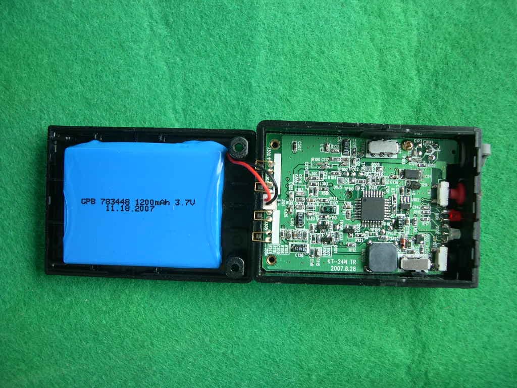
PE3KT-24NT
Apr 02, 2008DIGITAL TRANSMISSION SYSTEM
Equipment Class
DSS - Part 15 Spread Spectrum Transmitter