PE3WPM-2400TDIGITAL WIRELESS MICROPHONE SYSTEM
ISV Co., Ltd.
Click to zoom
Application Details
- Equipment Class
- DSS - Part 15 Spread Spectrum Transmitter
- Date of Grant
- Aug 31, 2010
- Application Purpose
- Original Equipment
- Date of Application
- Aug 30, 2010
- Equipment Note
- DIGITAL WIRELESS MICROPHONE SYSTEM
- Frequency Range
- 2401.05600000 - 2482.27200000
- Company
- ISV Co., Ltd.
- Country
- South Korea
Documents & Files
Document Text
Text extracted from the exhibit documents filed with the FCC. Open a document above to read the original.
Users Manual
2.4GHZ Digital Wireless Microphone System USER GUIDE TABLE OF CONTENTS 1. Description of the units ....................................... ........................3 1. Quick Set Up and Operation .......................................................4 2. Installation....................................................................................5 3. Guidelines For Best Performance................................................6 4. Troubleshooting Guide.................................................................7 5. Technical Specifications...............................................................8 6. Factory Service ............................................................................9 7. Warranty......................................................................................9 8. Accessories and Parts ............................... ...................................9 DESCRIPTION Receiver Transmitter Green LED: In-use, Record RED LED: Charging Green LED: Full charge Terminal For charging Antenna Connection Modular Jack Audio Jack Input Record Button Lapel Mic. Cover Emergency Button Green: In-use (Light On) Record (Flashing) RED LED: Out of Range RED LED: Low Battery Audible and Vibration Selectable Switch Power On/Off Switch 1. QUICK SET UP AND OPERATION Synching Up the Transmitter and Base The synch operation only needs to be performed the first time a system is used, or a new bodypack is used with a base previously synched to another bodypack. Do not perform the synch operation multiple times; it only needs to be done one time when a new bodypack is used with a new base. 1) Turn the transmitter power switch to ON and place the transmitter in the recharge cradle of the base. The transmitter goes in the base with the belt clip facing out. 2) The recharge LED will light (Green if fully charged, Red if charging). Leave the transmitter in the cradle for 4 hours for a full charge. 3) Press the REC button on the transmitter and hold until the In-Use LED on the transmitter and base start to flash, then release the button. 4) After a few seconds the light will stop flashing, and a beep will sound (If the beep is enabled). 5) The transmitter and base are now synched and will continue to be until another transmitter is linked to that base. Normal Operation 1) With the transmitter synched up, remove it from the cradle, plug in the lapel microphone (if used) and place the transmitter on your belt. 2) When you remove Transmitter from the cradle, The TR and Base’s In-USE LED will light a constant Green and you will hear short beep. To start the recording, press the REC button and the In-Use LED will blink in green. 3) To end recording, press the REC button and the In-Use LED will light a constant green. 4) At the end of your shift turn the transmitter off and replace it in the charging cradle. Out of Range 1) The transmitter will alert you with Audible warning beeps (two tone) and the In-Use LED will blink in red. 2) Move closer to the receiver base and the link will be re-established once you return to normal range. The In-Use LED will light constant green when link is back to normal operation. 3) If the link is not re-established within 30 seconds, the transmitter and receiver will return to standby mode. 4) If you went out of range in Standby mode, or the unit reverted to standby mode, re-enter normal range and press the In-Use button. Operation will return to normal. 5) If you will be out of range for a long period of time, turn the bodypack off. Low Battery Warning 1) If the transmitter Low BATT indicator (red) starts flashing or you hear warning beeps, return the transmitter to its cradle on the receiver to fully charge the transmitter. 2) The Charge LED indicator will light constant green when the unit is fully charged. EMG Panic Button (if wired for use in your vehicle) 1) The EMG or Panic Button can be programmed to do many things but may not be connected in your vehicle. Check with your technical department to understand what this button will control before you use it. 2) In Record mode: Press the EMG button on the transmitter, a beep will sound and the relay will be triggered at the receiver. 3) In Standby mode: Press the EMG button on the transmitter, a beep will sound, the green In-Use indicator will blink and the relay will be triggered at the receiver. Disabling the Beep Sound On the Transmitter 1) All of the audible beep signals on the transmitter can be disabled by setting the BEEP switch to the off position. Record Trigger (if video recording equipment supports) 1) The Record trigger feature is used to turn on recording whenever the video recorder is turned on. Some video record units can be triggered by other events (lights and siren being turned on etc.) and ensures the microphone starts recording at the same time. The transmitter must be turned on and in standby mode. 2) A +12V signal on the line means the microphone is Record off. 3) 0V or ground on the line turns on the microphone is Record on. 2. INSTALLATION PIN DESCRIPTION OF THE BASE OUTPUT PORT Connector wire (RJ45) Pin #1 : Transmitter Audio out Pin #2 : In Car Mic. Audio out Pin #3 : 12V DC_IN Pin #4 : Ground Pin #5 : Record Trigger OUT Pin #6 : Record Trigger IN Pin #7 : Panic Trigger Out Pin #8 : In Car Mic. Trigger IN Terminated Connector ( Optional ) Type A 1) Wire the un-terminated signal wires to the control unit according to the signal chart. 5 Amp fast blow fuse is recommend in the 12VDC power supply line to protect the equipment. 2) Plug the 3.5mm stereo plug into the audio input jack of the recording device. 3) If it is to be used, plug in the in-car microphone into the In-Car Mic jack in the side of the receiver base. 4) Turn on the transmitter and place it in the charging cradle with the beltclip facing out. The Charge LED will light if there is power. If the LEDs do not come on, check the connections and repeat. Description Position Audio Ground Sleeve Transmitter Audio Ring Ins…
Text truncated - open the document above for the full version.
Cover Letter(s)
ISV Co., Ltd. E-Mail : [email protected] Tel. : 82-32-329-8921Fax. : 82-32-327-1125 August 17, 2010 Federal Communications Commission Authorization and Evaluation Division Confidentiality Request regarding application for certification of FCC ID: PE3WPM-2400R Pursuant to Sections 0.457 and 0.459 of the Commission’s Rules, we hereby request confidential treatment of information accompanying this application as outlined below: Exhibit Type File Name Part List CONF APPENDIX – WPM-2400T - Part List.PDF Schematics Diagram(s) CONF APPENDIX - WPM-2400T – Schemetics.PDF Block diagram CONF APPENDIX - WPM-2400T – Block diagram.PDF The above materials contain trade secrets and proprietary information not customarily released to the public. The public disclosure of these materials may be harmful to the applicant and provide unjustified benefits to its competitors. The applicant understands that pursuant to Section 0.457 of the Rules, disclosure of this application and all accompanying documentation will not be made before the date of the Grant for this application. Sincerely,
External Photos
www.kes.co.kr FCC ID: PE3WPM-2400T Page 1 of 1 EUT External Photographs
ID Label/Location Info
www.kes.co.kr FCC ID label and Location Label
Internal Photos
www.kes.co.kr EUT Internal Photographs www.kes.co.kr
Operational Description
2-Layer 2G4 RF Reference Design Page 5 of 16 This document and the information contained is property of RTX Telecom A/S, Denmark. Unauthorized copying is not allowed. The information in this document is believed to be correct at the time of writing. RTX Telecom A/S reserves the right at any time to change said content, circuitry and specifications. 2 Technical description 2.1 Block diagram The LMX4268 transceivers require only a few external circuits. The block diagram in figure 1 represents the RTX RF module. The baseband controller (NSC SC14408) controls the LMX by a Microwire interface and by other baseband signals. The interface is described in detail in section 2.7. LNA PAD LMX4x68 PA Power ramp SW1 SW2 Logic control Baseband controller PLL Loop filter Baseband controller Figure 1. Block diagram of RF module employing the LMX4268. Only two logic ports are used in the Reference Design Kit. The four logic ports are capable of controlling auxiliary circuits, such as activating the power amplifier (PA) and controlling the RX/TX switch. If preamble antenna diversity is to be employed, the baseband processor should control the antenna switches. Both the PA-driver and the LNA require balanced signals. Baluns must be placed at the LNA input and the PA driver output. It is recommended to have the schematics of the RTX module at hand before proceeding. 2.2 Front-end The RTX RF module has two antenna ports. Two PIN diodes controlled by the baseband processor are used for routing the desired antenna to the RX/TX path. Preamble antenna diversity, also known as fast antenna diversity, is supported by this solution. The LMX4268 also features built-in preamble antenna diversity, and has two output ports for driving the antenna switches. Using the bidirectional microwire interface, it can be read-back which antenna was chosen for a receive slot. That same antenna is usually selected for the following transmit slot. Mounting options determine the diversity function of the Kit. 2-Layer 2G4 RF Reference Design Page 6 of 16 This document and the information contained is property of RTX Telecom A/S, Denmark. Unauthorized copying is not allowed. The information in this document is believed to be correct at the time of writing. RTX Telecom A/S reserves the right at any time to change said content, circuitry and specifications. RX/TX switching is accomplished using two PIN diodes, one in the signal line from the power amplifier, and a shunt diode placed a quarter of a wavelength towards the LNA. Logic ports on the transceiver control the diodes. When the two diodes are forward biased, the PA signal is routed towards the antennas, and the shunt diode shorts the signal to ground. However, the quarter-wave microstrip transforms this short into a high-impedance load. This construction has the advantage of very low loss and low power consumption in receive mode. A band pass filter is used to protect the receiver from blocking signals and to attenuate certain spurious emissions, such as the 3 rd and 4 th harmonic of the VCO. For 2.4GHz ISM systems there are no formal requirements for receiver immunity to other systems. The LMX4268 receivers have some frequencies that are subject to blocking, namely the fundamental as well as the first harmonics of the VCO. Using band pass filters generally increases immunity to other systems, and gives a better product. To control the power envelope in transmit mode, the power amplifier supply voltage is switched. A logic port on the transceiver activates the supply power to the power amplifier. The used power amplifier has integrated switching. Ramping up or down the PA is prone to cause transient emissions or even frequency offsets of the VCO. By proper ramping of the supply voltage transients can be avoided, and shielding the transceiver circuit isolates the VCO from the field surrounding the module. 2.3 PLL synthesizer The integrated integer-N PLL uses the 10.368MHz clock signal supplied by the baseband chip as reference frequency. The phase detector operates at 432kHz, which gives a channel spacing of 864kHz, because the prescaler is connected to the VCO output at half the transmit frequency. Please refer to the data sheet for specific A- and B counter settings. The synthesizer requires an external loop filter between the charge pump output and the VCO tune input. The lock-in time of the PLL and open-loop drift depends on this filter. The LMX4268 uses open-loop modulation, where the gaussian shaped transmit signal is applied directly to the VCO modulation input. This implies tri-stating the charge pump when transmitting a burst of data. This also conveniently prohibits the front-end from transmitting any spurious emissions generated by the synthesizer. During the lock-in phase of the synthesizer, it is critical that the modulation input to the VCO is kept at the mean voltage of the modulation that will be applied during the actual transmission. If this is not the case, a frequency offset will be present. If the modulation input 2-Layer 2G4 RF Reference Design Page 7 of 16 This document and the information contained is property of RTX Telecom A/S, Denmark. Unauthorized copying is not allowed. The information in this document is believed to be correct at the time of writing. RTX Telecom A/S reserves the right at any time to change said content, circuitry and specifications. of the VCO is not linear, it may be beneficial to modulate the VCO in the lock-in period with a pattern similar to the preamble (alternating zeroes and ones). The 10.368MHz reference frequency is used by the digital circuitry as well as reference for the synthesizer. This means that the reference frequency cannot be switched off, even when the PLL is not active. 2.4 Power up, calibration and initialization After power up or reset, the chip must be calibrated and initialized. Calibrating IF filter response and DC-offset at the ADC input compensates for manufacturing tolerances. The calibration is fully autom…
Text truncated - open the document above for the full version.
Operational Description
Specification For Approval Antenna Type PF - ANT Model Name WPM-2400T - ANT Part No SAE HAN ANTENNA CO.,LTD CONTENTS 1. Specification ............................................ 3 2. Electrical Specification Test 2.1 V.S.W.R .............................................4 2.2 Beam Pattern .............................................6 1. Specification 1.1. General Specification General specification Model name WPM – 2400T Antenna type 1/4 Wavelength PF Antenna 1.2. Electrical Specification Electrical specification Center Frequency 2438MHz Frequency Range 2400MHz – 2500MHz V.S.W.R Less Than 2.0 Gain(dBi) 2.05dBi (Max) Radiation pattern Omni-directional Polarization Vertical Impedance 50Ω Normal ± 20 1.3. Mechanical Specification Mechanical specification Connector Type Soldering Cover Material Drawing reference Color Silver Temperature Range -45°C ~ +85°C Weight 1g ± 0.2g Dimension Drawing reference 2. V.S.W.R Test ① Network Analyzer Spec Equipment Model Specification Network Analyzer HP8753ES · Freq. Range : 300KHz ~ 6GHz Calibration Kit HP85032B · DC ~ 6GHz (SMA-Type) ② Network Analyzer test method 2.1 V.S.W.R DATA Frequency V.S.W.R 비 고 2400 MHz 1.36 2450MHz 1.27 2500MHz 1.74 2.2 Gain & Beam Pattern Test ① Chamber Spec Section Specification Chamber Size 5(L)m X 5.5(W)m X 5(H)m Frequency Range 800MHz – 60GHz (Far Field) Quiet Zon 1m X 1 m @ 1GHz Type Rectangular Antenna weight < 50 kg ② Chanmber Test method Positioner Control Microwave Receiver Printe r Roll Positioner GPIB RF Cables S ystem Cable Far Field Measurement Software System Controller Az/El/Az Positioner Antenna Under Test Standard Gain Horn Antenna 2.3. Gain & Beam Pattern H-Plane 주 파 수 Gain(Max) 비 고 2400MHz -2.69dBi 2450MHz -1.01dBi 2500MHz -1.28dBi E-Plane Frequency Gain(Max) 비 고 2400MHz -0.63dBi 2450MHz -0.76dBi 2500MHz -1.51dBi
RF Exposure Info
www.kes.co.kr Page 1 of 2 RF EXPOSURE EVALUATION Applicant : ISV Co., Ltd. Applicant Address 102-705, Pucheon Technopark 364 Samjung-Dong, Ojun-Gu, Pucheon-Si, Korea Kind of Product : Digital Wireless Microphone System Equipment model name : PWM-2400T Antenna type : PIFA antenna Gain 2.05dBi Frequency Range : 2401.056 ~ 2482.272 MHz Number of channels : 95Channels www.kes.co.kr Page 2 of 2 ** MPE Calculations ** The EUT will only be used with a separation of 20 centimeters or greater between the antenna and the body of the user. The MPE calculation for this exposure is shown below. The peak radiated output power (EIRP) is calculated as follows: EIRP = P + G EIRP = 10.42 dBm Where, P = Power input to the antenna (mW) G = Power gain of the antenna (dBi) The numeric gain(G) of the antenna with a gain specified in dB is determined by: G = Log -1 (dB antenna gain / 10) G = Log -1 (2.05/ 10) G = 1.61 Power density at the specific separation: S = PG/(4R 2 π) S = (8.37 * 1.61 / (4 * 20 2 * π) S = 0.0022 mW/cm 2 Where, S = Maximum power density (mW/cm 2 ) P = Power input to the antenna (mW) G = Numeric power gain of the antenna R = Distance to the center of the radiation of the antenna (20cm = limit for MPE) The Maximum permissible exposure (MPE) for the general population is 1 mW/cm 2 . The power density at 20cm does not exceed the 1 mW/cm 2 limit. Estimated safe separation: R = √(PG / 4π) R = √(8.37 * 1.61/ 4π) R = 0.94 cm Where, P = Power input to the antenna (mW) G = Numeric power gain of the antenna R = Distance to the center of the radiation of the antenna (20cm = limit for MPE)
Test Report
www.kes.co.kr Test Report No.: TK-FR10031 Model No: WPM-2400T Page 1 of 29 This Report shall not be reproduced except in full without the written approval of THRU-KES CO.,LTD. TEST REPORT For FCC Test Report No. : TK-FR10031 Date of Issue : 08/24/2010 FCC ID : PE3WPM-2400T Description of Product : Digital Wireless Microphone System Model No. : WPM-2400T Applicant : ISV Co., Ltd. 102-705, Pucheon Technopark 364 Samjung-Dong, Ojun-Gu, Pucheon-Si, Korea Manufacturer : ISV Co., Ltd. 102-705, Pucheon Technopark 364 Samjung-Dong, Ojun-Gu, Pucheon-Si, Korea Standards : FCC Part 15.247 Test Date : 08/10/2010 – 08/24/2010 Test Results : PASS FAIL The test results relate only to the items tested. Tested by: Reviewed by: Kyu-Chul Shin KT Kang Test Engineer Technical Manager Date:08/24/2010 Date: 08/24/2010 THRU-KES CO.,LTD. 477-6, Hager-Ri, Yoju-Up, Yoju-Gun Kyunggi-Do,469-803, Korea Tel: +82-31-425-6200 / Fax: +82-31-424-0450 www.kes.co.kr Test Report No.: TK-FR10031 Model No: WPM-2400T Page 2 of 29 This Report shall not be reproduced except in full without the written approval of THRU-KES CO.,LTD. TABLE OF CONTENTS 1.0 General Product Description ...............................................................................3 1.1 Tested Frequency .............................................................................................3 1.2 Tested Mode ....................................................................................................3 1.3 Model Differences .............................................................................................4 1.4 Device Modifications .........................................................................................4 1.5 Peripheral Devices ............................................................................................4 1.6 Calibration Details of Equipment Used for Measurement .........................................5 1.7 Test Facility......................................................................................................5 1.8 Laboratory Accreditations and Listings .................................................................5 2.0 Summary of tests .............................................................................................6 2.1 Technical Characteristic Test...............................................................................7 2.1.1 Carrier Frequency Separation .......................................................................7 2.1.2 Number of Hopping Frequencies ...................................................................9 2.1.3 20 dB bandwidth ...................................................................................... 11 2.1.4 Time of Occupancy (Dwell Time) ................................................................. 13 2.1.5 Maximum peak Conducted Output Power...................................................... 15 2.1.6 Band-edge............................................................................................... 18 2.1.7 Field Strength of Emissions ........................................................................ 23 2.1.8 AC Conducted Emissions............................................................................ 28 APPENDIX A – Test Equipment Used For Tests ................................................................ 29 www.kes.co.kr Test Report No.: TK-FR10031 Model No: WPM-2400T Page 3 of 29 This Report shall not be reproduced except in full without the written approval of THRU-KES CO.,LTD. 1.0 General Product Description Equipment model name : WPM-2400T Serial number : Prototype EUT condition : Pre-production, not damaged Antenna type : PIFA antenna Gain 2.05dBi Frequency Range : 2401.056 ~ 2482.272 MHz RF output power : 8.37 dBm Peak Conducted Number of channels : 95 Type of Modulation(Data Rate) : GFSK Power Source : DC 3.7V(Li-ion Battery) 1.1 Tested Frequency LOW MID HIGH Frequency (MHz) 2401.056 2441.664 2482.272 1.2 Tested Mode - Pre-Scan has been conducted to determine the worst-case mode from all possible combinations between available modulations, data rates and antenna ports (if EUT with antenna diversity architecture). - Following channel(s) was (were) selected for the final test as listed below. Tested Ch Modulation Technology Modulation Type Low,Mid, High FHSS GFSK www.kes.co.kr Test Report No.: TK-FR10031 Model No: WPM-2400T Page 4 of 29 This Report shall not be reproduced except in full without the written approval of THRU-KES CO.,LTD. 1.3 Model Differences Not applicable 1.4 Device Modifications The following modifications were necessary for compliance: Not applicable 1.5 Peripheral Devices Device Manufacturer Model No. Serial No. FCC ID or DoC EUT ISV Co., Ltd. WPM-2400T - - Notebook F U J I T S U L T D LIFEBOOK S-5582 434230343466 DoC www.kes.co.kr Test Report No.: TK-FR10031 Model No: WPM-2400T Page 5 of 29 This Report shall not be reproduced except in full without the written approval of THRU-KES CO.,LTD. 1.6 Calibration Details of Equipment Used for Measurement Test equipment and test accessories are calibrated on regular basis. The maximum time between calibrations is one year or what is recommended by the manufacturer, whichever is less. All test equipment calibrations are traceable to the Korea Research Institute of Standards and Science (KRISS), therefore, all test data recorded in this report is traceable to KRISS. 1.7 Test Facility The measurement facility is located at 477-6, Hager-Ri, Yoju-Up, Yoju-Gun Kyunggi- Do,469-803, Korea. Tel: +82-31-883-5092/Fax: +82-31-883-5169. The sites are constructed in conformance with the requirements of ANSI C63.7, ANSI C63.4 and CISPR Publication 22. 1.8 Laboratory Accreditations and Listings Country Agency Scope of Accreditation Logo USA FCC 3 & 10 meter Open Area Test Sites and one conducted site to perform FCC Part 15/18 measurements. 343818 KOREA KCC EMI (10 meter Open Area Test Site and two conducted sites) Radio(3 & 10 meter Open Area Test S…
Text truncated - open the document above for the full version.
Test Setup Photos
www.kes.co.kr Test Setup Photos and Configuration Radiated Electric Field Emissions
Contact Information
Applicant
Martin H Kim(R & D Director)
Test Firm
KES Co., LtdInsung Ryu
Technical Specifications
| # | Rule Parts | Frequency Range | Power Output |
|---|---|---|---|
| 1 | 15C | 2.40 GHz - 2.48 GHz | 7.00 mW |
Other Applications from ISV Co., Ltd.

PE3DOYAK12-R
Sep 19, 2010BLUETOOTH USB DONGLE
Equipment Class
DSS - Part 15 Spread Spectrum Transmitter
PE3DOYAK12-T
Sep 19, 20102.4GHZ BT WIRELESS MOUSE
Equipment Class
DSS - Part 15 Spread Spectrum Transmitter
PE3WPM-2400R
Aug 31, 2010DIGITAL WIRELESS MICROPHONE SYSTEM
Equipment Class
DSS - Part 15 Spread Spectrum Transmitter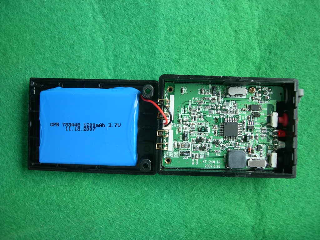
PE3KT-24NT
Apr 02, 2008DIGITAL TRANSMISSION SYSTEM
Equipment Class
DSS - Part 15 Spread Spectrum Transmitter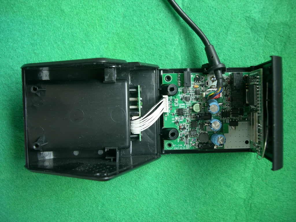
PE3KT-24NR
Apr 02, 2008DIGITAL TRANSMISSION SYSTEM
Equipment Class
DSS - Part 15 Spread Spectrum Transmitter