PERBM242A2.4GHz Baby Monitor
Tsuen Shing Enterprises Limited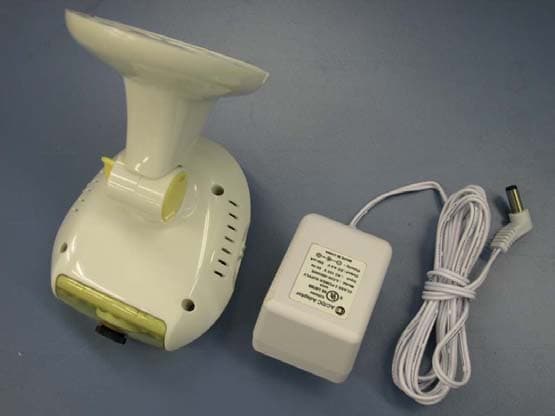
Click to zoom
Application Details
- Equipment Class
- DXX - Part 15 Low Power Communication Device Transmitter
- Date of Grant
- Aug 07, 2003
- Application Purpose
- Original Equipment
- Date of Application
- Aug 07, 2003
- Equipment Note
- 2.4GHz Baby Monitor
- Frequency Range
- 2414.00000000 - 2468.00000000
- Country
- Hong Kong
Documents & Files
Document Text
Text extracted from the exhibit documents filed with the FCC. Open a document above to read the original.
Users Manual
WIRELESS 2.4GHz HANDHELD BABY MONITOR BM-242 USER MANUAL Congratulations Giving birth to baby is the happiest experience for parents. They would offer their children the best living quality as they can and take care of them whole-heartedly. Therefore, a baby monitor is a necessary baby care product that helps parents pay attention to every wonderful moment of their baby. We have developed a 2.4G & 4 channels handheld slim size baby monitor that eliminates the interference from crowded 900MHz band. A color LCD screen allows the parents to watch their child. In addition, parents are able to see their baby in bright black & white view of baby even in a darkened room. If you want to see a bigger image of the baby on TV, a TV cable is included to help you. First time parents may find it difficult to manage the feeding time of their baby, a digital alarm clock is incorporated to remind the parents, “It’s time to feed the baby!” Please read all instructions thoroughly before using your Baby Monitor. Content and Features AC Adaptor: The AC Adaptors are low voltage power sources that allow you to use your household electricity to run the Baby Monitor. Connect the Ac Adaptors to the AC Adaptor Jack in the Parents and Baby Units. Both plug into any standard volt electrical outlet in your home. It is recommended to turn off the units before plug in or unplug the adaptors. CAUTION: These adaptors were made with a specific design for this product. They cannot be used with any other appliance. Never use a different type of adaptor with this monitor. Colour Monitor Power Indicator Indicator’s Statues Indication Flashing Red Light Batteries are charging Green Light Power is good Flashing Green Light Low power WA R N I N G ! TO REDUCE THE RISK OF FIRE OR ELECTRICAL SHOCK, DO NOT EXPOSE THIS PRODUCT TO WATER OR MOISTURE. NEVER ATTEMPT TO OPEN THE CASE OF EITHER THE BABY OR PARENTS UNIT. THIS IS DANGEROUS. 1. This product is not to be used as a medical monitor and its use should not replace proper adult supervision. It is important that an adult stays within the viewing range of the Baby Monitor at all time during use. 2. Always keep the Baby & Parents Units and AC adaptors out of child’s reach. Do not place the Baby Unit in child’s crib or playpen. 3. It is essential to check reception regularly. Please see the Testing section for complete instructions. 4. The Baby and Parents Units are for indoor use only. 5. NEVER use the Baby or Parents Units near water, such as bathtub, bathroom sink, laundry tub, kitchen sink or in a wet basement etc. 6. Always unplug the AC adaptors from wall outlets and remove the batteries or the exhausted batteries from the Parents Unit during long periods of non-use. 7. Position the Baby & Parents Units and AC adaptors to allow adequate ventilation and prevent these components from overheating. 8. To prevent overheating, keep the Baby & Parents Units and AC adaptors away from heat sources such as radiators, heat registers, stoves, other appliances (including amplifiers) or direct sunlight that produce heat. 9. Use only the AC adaptors provided. Use of any other adaptors may damage the Baby & Parents Units. Plug the AC adaptors into standard household current only! To prevent entanglement and overheating, DO NOT use extension cord. 10. Position the AC adaptor cords so that they are not walked on or pinched by items placed upon or against them, paying particular attention to cords at AC adaptor plugs, wall plugs, and the point at which the cords attached to the Baby & Parents Units. 11. The AC adaptors and battery compartment of the Parents Unit may become slightly warm to touch during operation. This is normal. Care and Maintenance 1. The Baby Monitor is for indoor use only. Do not place the Baby Unit under direct sunlight. Outdoor use may damage the Baby & Parents Units. 2. Clean the outer surface of Baby & Parent Units with a cloth dampened with water or mild cleaning solution LIGHTLY. Do not immerse any part of the product in water. 3. Do not drop the product or physically damage it, otherwise electronic components may be affected by such abuse. Caution: 1. Always remember that you are using public airwaves when you use the Baby Monitor. Sound and video may be broadcasted other receiving devices. Conversations, even from rooms near the Baby Unit may be broadcasted as well. To protect your privacy, always turn the Baby Unit off when not in use. 2. It is possible for the Parents Unit to pick up sounds or display interference from other signal producing devices including other audio or video monitors which broadcast in the 2.4GHz range. To minimize this potential problem, 4 independent channels are available for your use. 3. If the Parents Unit experiences interference, simply switch both the Baby & Parents Units to another channel. Selecting a channel is usually a one-time adjustment. If interference persists on all channels, please refer to the Troubleshooting Section. Te s t i n g It is very important to test the transmission of Baby Unit and reception of Parents Unit before use or whenever you change the location of either Parents / Baby Units. 1. Place Baby Unit in room where you intend to use it. Position it in the most appropriate location for monitoring the baby (on top of a table, dresser, or on the wall). Turn on the Baby Unit by switching the ON / OFF switch to ON. 2. Direct the camera lens towards the area you want to see on the Parents Unit screen. While testing, it may be helpful to place an object, such as a doll or stuffed animal, in the area you want to monitor. 3. Place the Parents Unit in different locations you intend to use inside the house. As with any audio equipment, feedback or a high pitched sound may occur if the Parents & Baby Units are too close to each other. 4. Set both units into the same channel. To test video reception quality 5. Check the video reception on the Parents Unit screen. Make sure you check the reception in all areas you intend to use …
Text truncated - open the document above for the full version.
External Photos
Test Setup FCC ID : PERBM242A External Photo -front External Photo - rear Test Setup FCC ID : PERBM242A External Photo - back
Internal Photos
Test Setup FCCID : PERBM242A Internal Photo - 1 Internal Photo - 2 Test Setup FCCID : PERBM242A Internal Photo - 3 Internal Photo - 4 Test Setup FCCID : PERBM242A Internal Photo - 5 Internal Photo - 6 Test Setup FCCID : PERBM242A Internal Photo - 7 Internal Photo - 8 Test Setup FCCID : PERBM242A Internal Photo - 9 Internal Photo - 10 Test Setup FCCID : PERBM242A Internal Photo - 11
Schematics
1 2 34 ABCD 4 3 2 1 D CBA 1 TSUEN SHING ELECTRONICS LTD 2 SCH-BM241ATX-01@A @A Title Size: Model No.: Rev.: Sheet of A4 2.4G BABY MONITOR(CAMERA) DWG.: DCzhang 2002-08-22 Drawing No.: CHK.:APP.: BM-241EU ENG-015-A C20100n D19 IN4004 1 23 SW21P2T D20LED + C19470uF C22100n + C21220U R372K2 +5V 123456789 10 J6610TX VIDEO +5VAGND AUDIO NAN/ACH1CH2CH3CH4 + C2547uF +5V 432 1 5 SW4 2P4T +9V VIDEOAUDIO Vin 1 Gnd 2 Vout 3 U37805 RF MODULE CON POWER SUPLY/DC 9V/5V 12 JP3CON2 +9V +5V +5V R600R610 MIC _ 2 + 3 GND 4 BP 7 O/P 5 G2 8 G1 1 VCC 6 U2 LM386 MIC R213K C8100n C29100n +C18 100uF +C9 10uF + C2710uF + C28100uF R2315kR224.7K R1910 R181K AUDIO +5V C178pF C158pF C168pF C148pF C128pF C138pF C118pF +9V+5V VIDEO GND 123JP1123JP2 +9VMICVIDEO+5V TP1 TP2 R5368 R210K C1 103
Test Report
E • The test results reported in this test report shall refer only to the sample actually tested and shall not refer or be deemed to refer to bulk from which such a sample may be said to have been obtained. • This report shall not be reproduced except in full without prior authorization from Intertek Testing Services Hong Kong Limited. • For Terms And Conditions of the services, it can be provided upon request. • The evaluation data of the report will be kept for 3 years from the date of issuance. Intertek Testing Services Hong Kong Ltd. 2/F., Garment Centre, 576 Castle Peak Road, Kowloon, Hong Kong. Tel: (852) 2173 8888 Fax: (852) 2371 0521 Tsuen Shing Enterprises Ltd. Application For Certification (FCC ID: PERBM242A) Transmitter 0308024 DL/Sandy July 8, 2003 INTERTEK TESTING SERVICES FCC ID: PERBM242A LIST OF EXHIBITS INTRODUCTION EXHIBIT 1: General Description EXHIBIT 2: System Test Configuration EXHIBIT 3: Emission Results EXHIBIT 4: Equipment Photographs EXHIBIT 5: Product Labelling EXHIBIT 6: Technical Specifications EXHIBIT 7: Instruction Manual EXHIBIT 8: Miscellaneous Information i INTERTEK TESTING SERVICES FCC ID: PERBM242A MEASUREMENT/TECHNICAL REPORT Tsuen Shing Enterprises Ltd. - MODEL: TS BM242A FCC ID: PERBM242A July 8, 2003 This report concerns (check one:) Original Grant X Class II Change Equipment Type: Low Power Transmitter (example: computer, printer, modem, etc.) Deferred grant requested per 47 CFR 0.457(d)(1)(ii)? Yes No X If yes, defer until: date Company Name agrees to notify the Commission by: date of the intended date of announcement of the product so that the grant can be issued on that date. Transition Rules Request per 15.37? Yes No X If no, assumed Part 15, Subpart C for intentional radiator - the new 47 CFR [08-20-02 Edition] provision. Report prepared by: Derek Leung Intertek Testing Services 2/F., Garment Center, 576, Castle Peak Road, HONG KONG. Phone: 852-2173-8504 Fax: 852-2371-0521 ii INTERTEK TESTING SERVICES FCC ID: PERBM242A Table of Contents 1.0 General Description............................................................................................................2 1.1 Product Description...........................................................................................................2 1.2 Related Submittal(s) Grants...............................................................................................2 1.3 Test Methodology..............................................................................................................3 1.4 Test Facility.......................................................................................................................3 2.0 System Test Configuration .................................................................................................5 2.1 Justification........................................................................................................................5 2.2 EUT Exercising Software..................................................................................................5 2.3 Special Accessories............................................................................................................5 2.4 Equipment Modification....................................................................................................6 2.5 Measurement Uncertainty..................................................................................................6 2.6 Support Equipment List and Description............................................................................6 3.0 Emission Results ..................................................................................................................8 3.1 Field Strength Calculation..................................................................................................9 3.2 Radiated Emission Configuration Photograph..................................................................11 3.3 Radiated Emission Data...................................................................................................12 3.4 Conducted Emission Configuration Photograph...............................................................14 3.5 Conducted Emission Data..................................................................................................... 15 4.0 Equipment Photographs ...................................................................................................17 5.0 Product Labelling ..............................................................................................................19 6.0 Technical Specifications ....................................................................................................21 7.0 Instruction Manual ...........................................................................................................23 8.0 Miscellaneous Information ...............................................................................................25 8.1 Bandedge Plot..................................................................................................................26 8.2 Discussion of Pulse Desensitization.................................................................................27 8.3 Emissions Test Procedures...............................................................................................28 iii INTERTEK TESTING SERVICES FCC ID: PERBM242A List of attached file Exhibit type File Description filename Test Report Test Report report.pdf Operation Description Technical Description descri.pdf Test Setup Photo Radiated Emission radiated photos.doc Test Setup Photo Conducted Emission conducted photos.doc Test Report Conducted Emission Test Result conducted.pdf Test Report Bandedge Plot be.pdf External Photo External Photo external photos.doc Internal Photo Internal Photo internal photos.doc Block Diagram Block Diagram block.pdf Schematics Circuit Diagram circuit.pdf ID Label/Location Label Artwork and Location…
Text truncated - open the document above for the full version.
Test Setup Photos
Test Setup FCC ID : PERBM242A Radiated - front Radiated - rear
Contact Information
Applicant
M Q Cheng(General Manager)
Technical Contact
Intertek Testing Services Hong KongDerek Leung
[email protected](852)2173 8504
2/F., Garment Centrre, · Kowloon · Hong Kong
Non-Technical Contact
Intertek Testing Services Hong KongDerek Leung
[email protected](852)2173 8504
Test Firm
Intertek Testing Services Hong KongBilly Chow
Technical Specifications
| # | Rule Parts | Frequency Range | Power Output |
|---|---|---|---|
| 1 | 15C | 2.41 GHz - 2.47 GHz | - |
Other Applications from Tsuen Shing Enterprises Limited
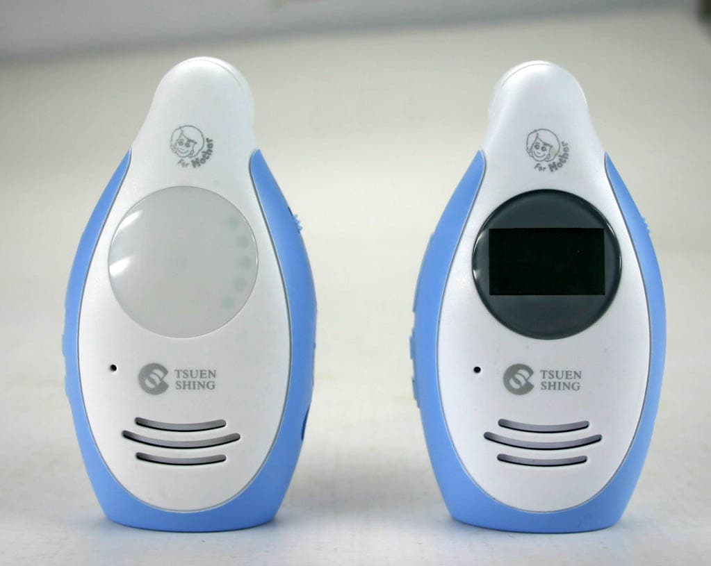
PERBM-148RX
Apr 03, 20072.4GHz DIGITAL BABY PHONE (WITH LCD/ WITH LED)
Equipment Class
DSS - Part 15 Spread Spectrum Transmitter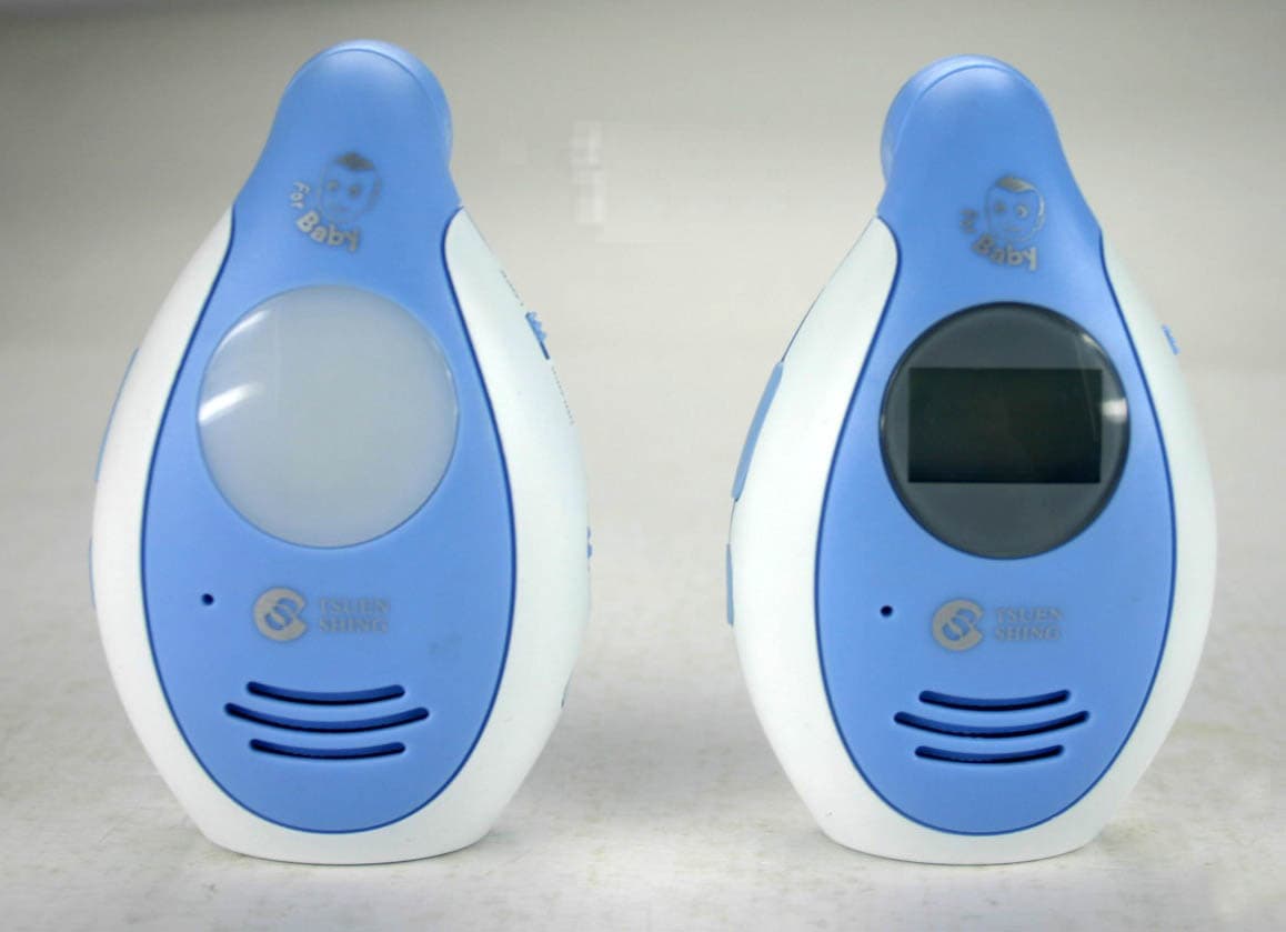
PERBM-148TX
Apr 03, 20072.4GHz DIGITAL BABY PHONE (WITH LCD/ WITH LED)
Equipment Class
DSS - Part 15 Spread Spectrum Transmitter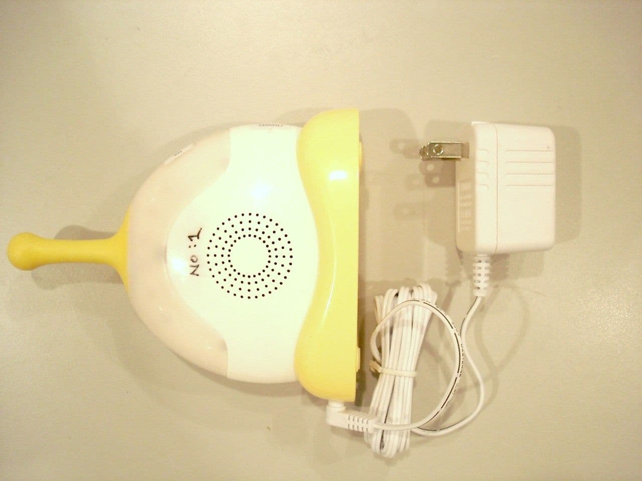
PER-DBM1001RX
Sep 08, 2005Winnie The Pooh Baby Phone
Equipment Class
CYY - Communications Receiver used w/Pt 15 Transmitter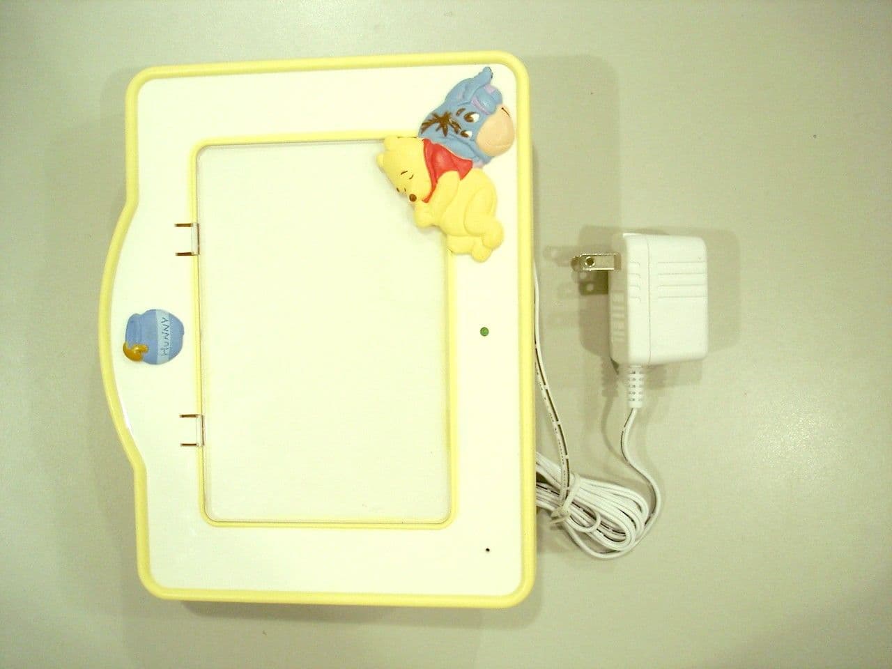
PER-DBM1001TX
Sep 06, 2005WINNIE THE POOH BABY PHONE
Equipment Class
DXX - Part 15 Low Power Communication Device Transmitter
PERWT418
Apr 27, 200422 channels FRS+GMRS
Equipment Class
FRF - Part 95 Family Radio Face Held Transmitter