PF5-18ALCD Monitor
NEWCOMM World Co., Ltd.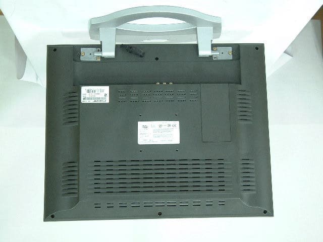
Click to zoom
Application Details
- Equipment Class
- JBP - Part 15 Class B Computing Device Peripheral
- Date of Grant
- Aug 06, 2002
- Application Purpose
- Original Equipment
- Date of Application
- Aug 06, 2002
- Equipment Note
- LCD Monitor
- Company
- NEWCOMM World Co., Ltd.
- Country
- South Korea
Documents & Files
Document Text
Text extracted from the exhibit documents filed with the FCC. Open a document above to read the original.
Users Manual
Color TFT-LCD Monitor User’s Manual TM181 ... SXGA TM181 ... SXGA TM181 Notes On LCD Monitors Color TFT-LCD Monitor 1.The LCD panel used in this monitor is a very high technology product with 3,932,160 thin film transistors, giving you fine picture details. Occasionally, a few non-active pixels may appear on the screen as a fixed point of red, green, blue, white or black. Please note that this does not indicate a defective panel. 2. Set your resolution to 1280 x 1024 pixels at 60Hz refresh rate for optimum display quality. 3. Due to the nature of the LCD screen, an afterimage of the previous screen may remain after switching the image when the same image has been displayed for a long time. The monitor will slowly recover from this. 4. The screen surface is very soft. Do not rub, touch or tap the screen surface with sharp object such as pen or pencil. This contact may scratch or damage the screen. These damages are not covered under the warranty. TM181 OPERATION MANUAL Color TFT-LCD Monitor CONTENTS ...............4,5 ...............6 ...........................7 ........................8 ...11 .....................12 .......13,14,15 ...............16 SAFETY PRECAUTIONS SUPPLIED ACCESSORIES PREPARATION Remote Control TV Tuner LOCATION OF USERS CONTROL REMOTE CONTROL MONITOR INSTALLATION STATUS INFORMATION ........................9 Cable Connection ............10 Stand, Arm, Wall Mount OSD USAGE ......20 ..................................21 BEFORE CALLING FOR REPAIR SERVICE TM181 Available PC VGA Mode SPECIFICATIONS ........................17,18,19 ............22 WARRANTY STATEMENT..............23,24 FCC & ENERGYSTAR STATEMENTS ...25 HOW TO CONTACT US......................26 ...............................27,28V-Chip Appendix Improper use can result in electric shock and/or fire. In order to prevent potential danger, please observe the following instructions when installing, operating and cleaning the product. To ensure your safety and prolong the service life of your color TFT-LCD monitor product, please read the following precautions carefully before using the product. gAll operating instructions must be read and understood before the product is operated. gThese safety and operating instructions must be kept in safe place for future reference. gAll warnings on the product and in the instructions must be observed closely. gAll operating instructions must be followed. gDo not use attachments not recommended by the manufacturer. Useof inadequate attachments can result in accidents. gThis product must be operated on a power source specified on the specification label. If you are not sure of the type of power supply used in your home, consultyour dealer or local power company. For units designed to operate on batteries or another power source, refer to the operating instructions. gThe power cords must be routed properly to prevent people from stepping on them or objects from resting on them. Check the cords at the plugs and product. gIf you plan to use a 12V DC power supply unit other than the ACadapter supplied with the product, make sure the power supply unit provides stable voltage with minimum fluctuations. gDo not overload AC outlets or extension cords. Overloading can cause fire or electric shock. gNever insert an object into the product through vents or openings. High voltage flows in the product, and inserting an object can cause electric shock and/or short internal parts. For the same reason, do not spill water or liquid on the product. gDo not attempt to service the product yourself. Removing coverscan expose you to high voltage and other dangerous conditions. Request a qualified service person to perform servicing. gIf any of the following conditions occurs, unplug the power cordfrom the AC outlet, and request a qualified service person to perform repairs. a. When the power cord or plug in damaged. b. When a liquid was spilled on the product or when objects have fallen into the product. c. When the product has been exposed to rain or water. d. When the product does not operate properly as described in the operating instructions. Do not touch the controls other than those described in the operating instructions. Improper adjustment of controls not described in the instructions can cause damage, which often requires extensive adjustment work by a qualified technician. e. When the product has been dropped or damaged. f. When the product displays an abnormal condition. Any noticeable abnormality in the product indicates that the product needs servicing. gIn case the product needs replacement parts, make sure that theservice person uses replacement parts specified by the manufacturer, or those with the same characteristics and performance as the original parts. Use of unauthorized parts can result in fire, electric shock and/or other danger. gUpon completion of service or repair work, request the servicetechnician to perform safety checks to ensure that the product is in proper operating condition. gWhen mounting the product on a wall or ceiling, be sure to install the product according to the method recommended by the manufacturer. SAFETY PRECAUTIONS 4 gUnplug the power cord from the AC outlet before cleaning the product. Use a damp cloth to clean the product. Do not use liquid cleaners or aerosol cleaners. gUnplug the power cord from the AC outlet if you do not use the product for considerably long time. gDo not use the product near water, such as bathtub, washbasin, kitchen sink and laundry tub, swimming pool and in a wet basement. gKeep the product away from direct rays of the Sun-light. gDo not place the product on an unstable cart, stand, tripod or table. Placing the product on an unstable base can cause the product to fall, resulting in serious personal injuries as well as damage to the product. Use only a cart, stand, tripod, bracket or table recommended by the manufacturer or sold with the product. When mounting the product on a wall, be sure to follow the manufacturer's instru…
Text truncated - open the document above for the full version.
External Photos
Test report Our reference : KEL02-F07055 Page : B1 of Appendix Issued date : 2002-07-31 Appendix-B : External Photographs of E.U.T <FRONT VIEW OF EUT> <REAR VIEW OF EUT>
ID Label/Location Info
Test report Our reference : KEL02-F07055 Page : D1 of Appendix Issued date : 2002-07-31 Appendix-D : FCC ID label location information and Sample - FCC ID label location information The label included following statement will be attached on the rear side of product. - FCC ID label sample
Internal Photos
Test report Our reference : KEL02-F07055 Page : C1 of Appendix Issued date : 2002-07-31 Appendix-C : Internal Photographs of E.U.T <INTERNAL VIEW OF E.U.T> Test report Our reference : KEL02-F07055 Page : C2 of Appendix Issued date : 2002-07-31 <FRONT VIEW OF INVERTER BOARD> Test report Our reference : KEL02-F07055 Page : C3 of Appendix Issued date : 2002-07-31 <REAR VIEW OF INVERTER BOARD> Test report Our reference : KEL02-F07055 Page : C4 of Appendix Issued date : 2002-07-31 <FRONT VIEW OF MAIN Board> Test report Our reference : KEL02-F07055 Page : C5 of Appendix Issued date : 2002-07-31 <REAR VIEW OF MAIN Board > Test report Our reference : KEL02-F07055 Page : C6 of Appendix Issued date : 2002-07-31 <FRONT VIEW OF LCD> Test report Our reference : KEL02-F07055 Page : C7 of Appendix Issued date : 2002-07-31 <REAR VIEW OF LCD> Test report Our reference : KEL02-F07055 Page : C8 of Appendix Issued date : 2002-07-31 <FRONT VIEW OF LCD Board> Test report Our reference : KEL02-F07055 Page : C9 of Appendix Issued date : 2002-07-31 <REAR VIEW OF LCD Board> Test report Our reference : KEL02-F07055 Page : C10 of Appendix Issued date : 2002-07-31 <FRONT VIEW OF OSD16 Board> Test report Our reference : KEL02-F07055 Page : C11 of Appendix Issued date : 2002-07-31 <REAR VIEW OF OSD16 Board > Test report Our reference : KEL02-F07055 Page : C12 of Appendix Issued date : 2002-07-31 <FRONT VIEW OF Adapter> Test report Our reference : KEL02-F07055 Page : C13 of Appendix Issued date : 2002-07-31 <REAR VIEW OF Adapter >
Test Report
CERTIFICATE OF COMPLIANCE 352 Youngduk-Ri, Kihung-Eup, Yongin-City, Kyunggi-Do, Korea 449-908 TEL : (82)31-206-4693 FAX : (82)31-206-3051 http://www.kesilab.com [email protected] http://www.koreaemc.co.kr [email protected] (CLASS B) CERTIFICATION OF COMPLIANCE is hereby issued to the named Applicant and is VALID ONLY for the equipment identified below: Date of Tested : July. 24. 2002 Applicant’s Name : Newcommworld Co., Ltd. Applicant’s Address : 328-5 Songnae-1Dong, Sosa-Gu, Puchon-Shi, Kyonggi-Do, 422-814, Korea Manufacturer’s Name : Newcommworld Co., Ltd. Manufacturer’s Address : 328-5 Songnae-1Dong, Sosa-Gu, Puchon-Shi, Kyonggi-Do, 422-814, Korea Declares that the product Product Description : LCD Monitor Brand Name : NEWCOMM Model Number : TM181 FCC ID : PF5-18A Conforms to FCC Rules and Regulations Part 15 Subpart B requirements. This product herewith complies with the requirements of the FCC Rules and Regulations as listed below: Part 15.107: Conducted Emissions. Part 15.109: Radiated Spurious Emissions. TESTED and CERTIFIED by: KOREA EMC LABORATORY 352 Youngduk-Ri, Kihung-Eup, Yongin-Si, Kyunggi-Do, 449-908, KOREA Date : July. 31. 2002 Report No : KEL02-F07055 Authorized Signature : M. S. CHO / President Test report Our reference : KEL02-F07055 Page : 2 of 13 Issued date : 2002-07-31 Korea EMC Laboratory TABLE OF CONTENTS DESCRIPTION Page 0. VERIFICATION OF COMPLIANCE 3 1. GENERAL INFORMATION 1.1 Product Description 4 1.2 Related Submittal(s)/Grant(s) 4 1.3 Tested System Details 4 1.4 System Configuration 4 1.5 General Setup of the test Shield room 5 1.6 Test Facility 5 2. Measurement Procedure 2.1 System test configuration 6 2.1.1 Video mode Justification 6 2.1.2 EUT Exercise S/W 6 2.2 Special Accessories 6 2.3 Equipment Modification 6 2.4 System Configuration Diagram 6 2.5 Preliminary testing 7 2.6 Shielded Enclosure 7 2.7 Data Reporting Format 7 2.8 Operating Condition 7 2.9 Conditioning of the EUT 7 2.10 Power Line Conducted Emissions 8 2.11 Open field Radiated Emissions Tests 8 3. Measurement Data 3.1 Conducted Emission Data 9 3.2 Conducted Emission Graph 10 3.3 Radiated Emission Data 11 3.4 Summary 12 4. Labeling Requirement 13 Appendix - A : Test set-up Photographs (Conducted and Radiated) - B : External Photographs of E.U.T - C : Internal Photographs of E.U.T - D : FCC ID label location information and sample - E : Block Diagram - F : User’s Manual Test report Our reference : KEL02-F07055 Page : 3 of 13 Issued date : 2002-07-31 Korea EMC Laboratory 0 . VERIFICATION OF COMPLIANCE Equipment Under Test : LCD Monitor Model Number : TM181 Serial Number : Prototype Manufacturer : Newcommworld Co., Ltd. 328-5 Songnae-1Dong, Sosa-Gu, Puchon-Shi, Kyonggi-Do, 422-814, Korea Type of Test : FCC CLASS B Report Number : KEL02-F07055 Date Tested : July. 24. 2002 Tested By : S.J.LEE The results show that the sample equipment tested as described in this reports is in compliance with the CLASS B conducted and radiated emission limits of FCC Rules Part 15, Subpart B. Test report Our reference : KEL02-F07055 Page : 4 of 13 Issued date : 2002-07-31 Korea EMC Laboratory 1. GENERAL INFORMATION 1.1 PRODUCT DESCRIPTION The TM181 is a LCD Monitor made by Newcommworld Co., Ltd. in Korea. Refer to the user's manual for more information. ITEM SPECIFICATION Resolution 1280 * 1024, SXGA Color 16,777,216 Colors (Full Color) Brightness 250 cd/m 2 (nit) Contrast Ratio 350 : 1 Viewing Angle H : 160 V : 160 Panel Type Amorphous Si TFT-LCD Actual Display size 359.04(H) x 287.23(V) mm Diagonal Length 18.1", 459.7mm Dimension (LxWxH) 480(W) x 425(H) x 62(D) mm 1.2 Related Submittal(s)/Grant(s) N/A 1.3 Tested System Details Type Model Name FCC ID Serial NO Manufacturer LCD Monitor TM181 PF5-18A Prototype Newcommworld Co., Ltd. Adapter LSE9901B1260 DoC NONE LI SHIN INTERNATIONAL ENTERPRISE CORP. NOTE PC SQ10 DoC A82691ET600040 Samsung Adapter AD-4212(K) DoC NONE Samsung Speaker 188825-301 NONE COMPAQ MIC RM-1000 NONE Hanil VTR SV-420 NONE Samsung 1.4 System Configuration Type Model Name Serial NO Manufacturer Remark INVERTER B/D MAIN B/D LCD LCD B/D OSD16 B/D DS-1008WC ASX6-01A LM181E05 LM181E05-C3 OSD16 NONE NONE NONE NONE NONE DS-Plus Inc. Newcommworld Co., Ltd. LG.PHILIPS LCD CO., LTD. LG.PHILIPS LCD CO., LTD. Newcommworld Co., Ltd. Korea Korea Korea Korea Korea Test report Our reference : KEL02-F07055 Page : 5 of 13 Issued date : 2002-07-31 Korea EMC Laboratory 1.5 General Set-up of the Test Shielded Room The EUT was set up in accordance with the suggested configuration given in FCC measurement Procedure ANSI C63.4, 2000. The measurement are performed in the shielded room which dimension is 3.0*7.0*2.5(m). The EUT was placed on a non conductive table which is 1.0*1.5(m), 80cm above an earthed ground plane and is kept at least 1m from any other earthed ground plane except the rear of table top being removed 40cm from a vertical conducting plane. Power to the EUT was provided through the LISN(3725/2,EMCO) which has the Impedance vs Frequency Characteristic in accordance with the Fig.1 Impedance Characteristic of LISN. Peripheral equipment required to provide a functional system(support equipment) for EUT testing was powered through another LISN(NSLK8128,Schwarzbeck). Power to the LISN was filtered to eliminate ambient signal interference. A coaxial type connector which provides a 50 Ohm terminating impedance was provided for the test instrument. The excess length of the power cord was wrapped in the two non metallic pegs attached to the top of the LISN. The two pegs are 9cm high, approximately 2.0 cm in diameter and that are spaced 6 cm on the center apart. 1.6 Test Facility Location: Korea EMC Laboratory 352 Yungduck-Ri Kihung-Eup,Yongin-City Kyungki-Do,Korea Site : - 3/10 m Open Fielded Radiated - Indoor Line Conducted Room(Shielded) The Open Field Radiated and Indoor Line Conducted sites are constructed and calibrated to meet the FCC requirements in documents ANSI C63.4 2000. Korea EMC Lab. was r…
Text truncated - open the document above for the full version.
Test Setup Photos
Test report Our reference : KEL02-F07055 Page : A1 of Appendix Issued date : 2002-07-31 Appendix-A : Test Setup Photographs - Conducted Setup Photographs LINE CONDUCTED SETUP PHOTOGRAPH - FRONT VIEW LINE CONDUCTED SETUP PHOTOGRAPH - REAR VIEW Test report Our reference : KEL02-F07055 Page : A2 of Appendix Issued date : 2002-07-31 - Radiated Setup Photograph RADIATED EMISSION SETUP PHOTOGRAPH - FRONT VIEW ( 30 - 300 MHz ) RADIATED EMISSION SETUP PHOTOGRAPH - REAR VIEW ( 30 - 300 MHz ) Test report Our reference : KEL02-F07055 Page : A3 of Appendix Issued date : 2002-07-31 RADIATED EMISSION SETUP PHOTOGRAPH - FRONT VIEW ( 300- 1000 MHz ) RADIATED EMISSION SETUP PHOTOGRAPH - REAR VIEW ( 300 - 1000 MHz )
Contact Information
Applicant
Hyun-Ki Hong(R&D Manager)
Test Firm
Korea EMC Laboratory Co., LtdMan-sung Cho
Technical Specifications
| # | Rule Parts | Frequency Range | Power Output |
|---|---|---|---|
| 1 | 15B | - | - |
Other Applications from NEWCOMM World Co., Ltd.
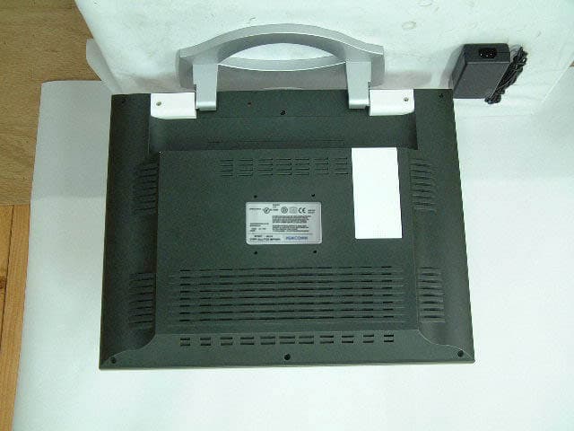
PF5-17A
Mar 21, 2002LCD Monitor
Equipment Class
JBP - Part 15 Class B Computing Device Peripheral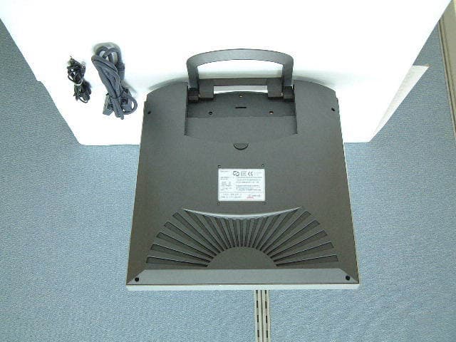
PF5-NLM155B
Mar 21, 2002LCD Monitor
Equipment Class
JBP - Part 15 Class B Computing Device Peripheral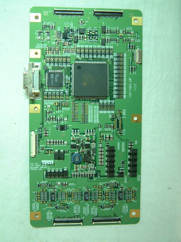
PF5TM800
Aug 21, 2001Monitor
Equipment Class
JBP - Part 15 Class B Computing Device Peripheral
PF5-TM400
Feb 12, 2001LCD Monitor
Equipment Class
JBP - Part 15 Class B Computing Device Peripheral
PF5-NLM155
Feb 12, 2001LCD Monitor
Equipment Class
JBP - Part 15 Class B Computing Device Peripheral