PFBM-LTH3-56-PCIModem
Serome Electronics Inc.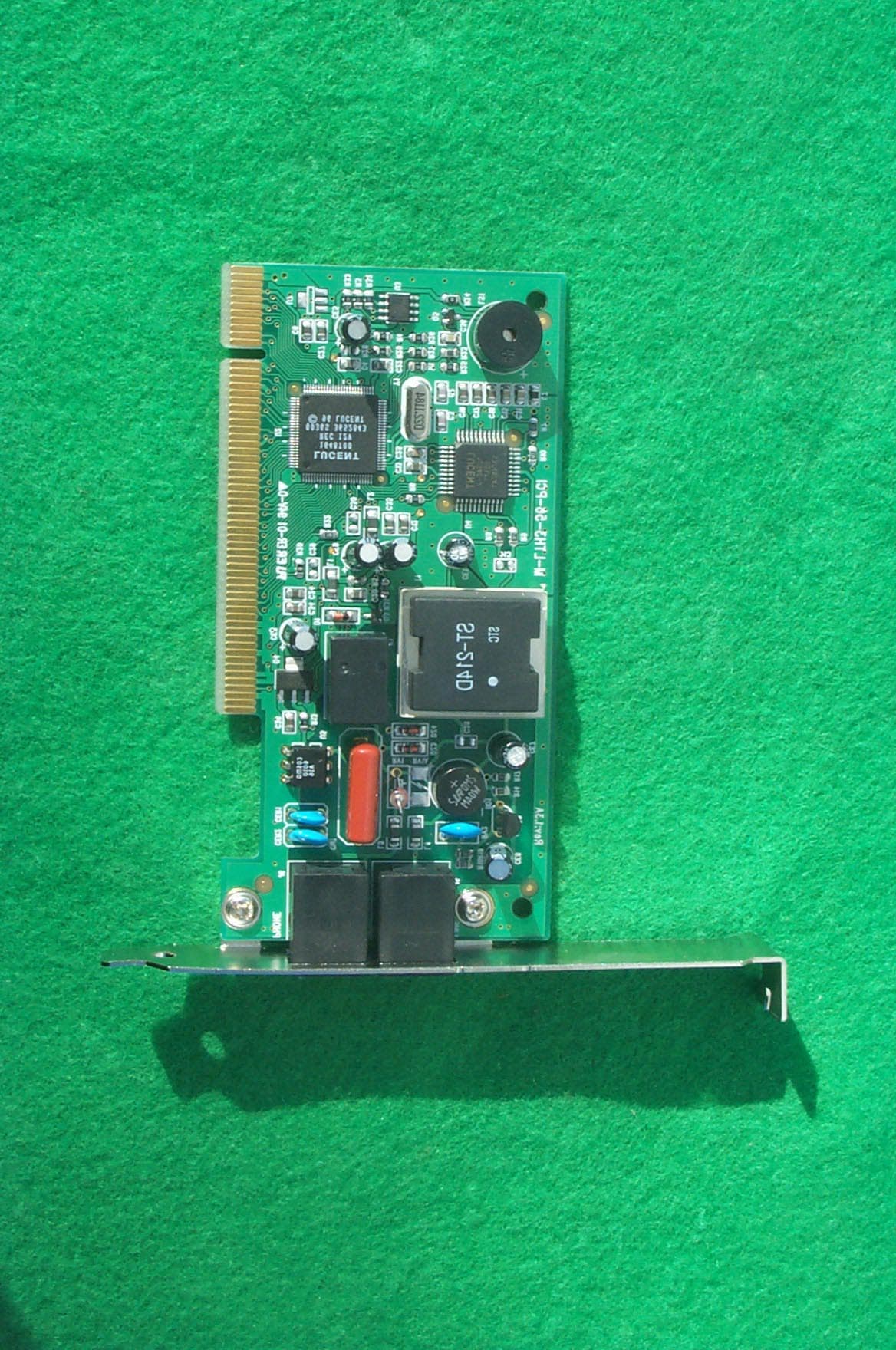
Click to zoom
Application Details
- Equipment Class
- JBP - Part 15 Class B Computing Device Peripheral
- Date of Grant
- Jan 18, 2001
- Application Purpose
- Original Equipment
- Date of Application
- Jan 18, 2001
- Equipment Note
- Modem
- Company
- Serome Electronics Inc.
- Country
- South Korea
Documents & Files
Document Text
Text extracted from the exhibit documents filed with the FCC. Open a document above to read the original.
Users Manual
1 Lucent Mars 3 PCI Modem User’s Manual Each Type User Guide A Class Machinery B Class Machinery This machinery is registered for its utilization of electromagnetic wave for business that the sellers or the users shall exercise care, and when it is sold or purchased for mistake, please replace it with one that is for family use. This machinery is registered for its utilization of electromagnetic wave for family that the sellers and the residential areas can also use this in all areas. 2 Copyright© 2000 Serome Electronics, Inc. All Rights Reserved. No part of this publication may be reproduced or distributed in any form or by any means, or stored in a database or retrieval system, without the prior written permission of the publisher. The contents of this User’s Manual may be changed or altered without prior notice due to the improvement or change of later products. Therefore, please make notice that there may be part that is not the same as the content of the Manual and the method of using the product. 3 INDEX I. Functions of Hardware ------------------------------------------------ 4 II. System Requirements------------------------------------------------- 4 1. Operation System Requirement 2. Hardware Requirement III. Installation of MODEM------------------------------------------------- 4 1. Automatic Setting of Modem Port 2. Installation of Modem 3. Telephone Line Connection IV. Driver Installation------------------------------------------------------ 6 Installation from Windows 98 1. When OS is installed 2. When OS is first installed or re-installed Installation at Windows 2000 V. Confirm the Installation of Modem-------------------------------- 11 Confirm at Windows 98 1. Install Modem at [manager] 2. Install Modem at [control panel] Confirm at Windows 2000 4 I. Functions of Hardware This product provides the maximum speed of 56,000 bps (maximum of 33,600 bps in up-roading) in up-roading when data communicating, and this is an improvement of about 1.5 ~ 2 times faster than the modem that provides the existing 28,800 bps or 33,600 bps. It is an appropriate product for sending and receiving of large capacity of multimedia information which requires a fast speed and it will give you satisfaction in utilizing your internet or PC communication. Simultaneous support of V.90 that is ITU-T standard and K56 flex of Lucent Company Providing maximum speed of 56,000 bps when downloading of data Providing maximum speed of 33,600 bps when downloading of data Providing maximum send/receive speed of 33,600 when communicating 1:1 Supporting the Hayes compatibility expansion AT command set Providing Class1, Class2 fax send/receive of 14,400 bps The international scale and specifications that this modem supports are as follows. 1. Data Mode Maximum Speed: 56,000 bps (33,600 bps when up-loading) Support Protocol: ITU-T V.90, V34, V32bis, V32, V22bis, V22, V.23, V.21, Bell 212A&103 Error Control Protocol: V42LAPM, MNP 2 ~4 Compressed control Protocol: V.42bis, MNP CLASS 5 2. Fax Mode Maximum Speed: 14,400 bps Fax Control Protocol: V.17, V.29, V.27ter, V.21ch2 GROUP3 Fax Command Set: EIA class 1 3. Interface PCI Interface II, System Requirements 1. Operation System Requirement This product is a modem that uses PCI interface, and is designed to operate only in the OS with the support of Plug and Play. Therefore, it operates only on Windows 95, Windows 98 and Windows NT, the OS that supports PnP, but not on the real mode DOS. However, it operates on the DOS mode in the Windows system. 2. Hardware Requirement This product can be used in a PC that is appropriate for PC 97 standard of Microsoft or better. The minimum specification requires a CPU with main board and Pentium MMX 200 that is equipped with extra PCU Slots. It is not guaranteed for a normal operation in the specification not meeting the above-mentioned minimum requirement. Also, the normal operation is not guaranteed on the CPU that does not use MMX technology even when the clock is over 200. III. Installation of MODEM This product is a embedded modem that uses the PCI Interface that, unlike the modem that has BUS method is the ISA type, it has to be used after it is installed in the PCI slot of the internal PC main body and then execute as the followings ※ Those who are confident in computer assembly may skip this section. 5 1. Automatic setting of Modem Port This product supports the PnP installation that there is no attachment of any adjustment on the modem board. However, it may be installed on the riser slot that is vacant on the main board. 2. Installation of Modem ① First, pull down the power of PC. The main board and power of recent time is mostly ATX that the complete pull off of power can prevent the damages to the other parts. ② And, open the cover of PC to look inside, then the main board is located and the other peripheral equipment cards are inserted. ③ Then, look for the empty PCI slot. And remove the guide by the nuts of guide that is fixed. ③ And, install modem and tighten the nuts to securely. At this time, take caution not to force it too much, which may damage the main board or modem. 3. Telephone Line Connection In the side of modem as shown on the below picture, there is a terminal that is marked for Line and Phone. Connection may be done by connecting the line that comes from the telephone of the family home to the line terminal, and the telephone is connected to the phone terminal. By doing so, the telephone is not operative while the modem is in operation, and the phone is usable when the computer is turned off. < Connecting Line and Phone > 6 IV. Driver Installation Since the interface of this modem is PCI modem, the installation procedure for slot is slightly different than the existing ISA method. The installation method is classified into two ways. ① When OS is already installed, and ② When OS is newly installed or re-installed while a modem is installed Install from Window 98 1. When OS is already installed In such cas…
Text truncated - open the document above for the full version.
Block Diagram
System Block Diagram System Block Diagram System Block Diagram System Block Diagram System Block Diagram System Block Diagram System Block Diagram System Block Diagram ROM CODED DSP 1648 100-pin TQFP CSP 1034C 48-pin TQFP System PCI Bus RingTip Analog DAA PC Host Processor
External Photos
SK TECH CO., LTD. Page 1 of 2 SKT SKTOS-01008 FCC ID : PFBM-LTH3-56-PCI External Photographs of EUT SK TECH CO., LTD. Page 2 of 2 SKT SKTOS-01008 FCC ID : PFBM-LTH3-56-PCI
ID Label/Location Info
SK TECH CO., LTD. Page 1 of 1 SKT SKTOS-01008 FCC ID : PFBM-LTH3-56-PCI FCC ID Sample Label & Location Information LABELLING REQUIREMENTS PER ∫∫∫∫ ∫∫∫∫∫∫∫∫ ∫∫∫∫2.928 The Label shown shall be permanently affixed at a conspicuous location on the device and be readily visible to the user at the time of purchase. FCC ID : PFBM-LTH3-56-PCI This device complies with part 15 of the FCC Rules. Operation is subject to the following two conditions: (1) This device may not cause harmful interference, and (2) this device must accept any interference received, including interference that may cause undesired operation.
ID Label/Location Info
SK TECH CO., LTD. Page 1 of 1 SKT SKTOS-01008 FCC ID : PFBM-LTH3-56-PCI FCC ID Label Sample
Internal Photos
SK TECH CO., LTD. Page 1 of 1 SKT SKTOS-01008 FCC ID : PFBM-LTH3-56-PCI Internal Photographs of EUT
Test Report
SK TECH CO., LTD. Page 1 of 13 SKT SKTOS-01008 FCC ID : PFBM-LTH3-56-PCI Certificate of Compliance Test Report No.: SKTOS-01008 NVLAP CODE : 200220-0 Applicant: Serome Electronics Inc. Applicant Address: 1025-1, Dogok-Ri, Waboo-Eub, Namyangjoo-City, Kyoungki-Do, Korea Product: Modem FCC ID: PFBM-LTH3-56-PCI Model No.: M-LTH3-56-PCI Receipt No.: SKE20010109-018 Date of receipt: Jan. 09, 2001 Date of Issue: Jan. 16, 2001 Testing location: SK TECH CO., LTD. 820-2, Wolmoon-Ri, Wabu-Up, Namyangju-Si, Kyunggi-Do, Korea Test Standards: ANSI C63.4 / 1992 Rule Parts: FCC part 15 Subpart B Equipment Class : Class B Digital Device Peripheral Test Result: The above mentioned product has been tested and passed. Prepared by:Y.H. Kang Tested by:S.W.Han/Engineer Approved by: J.Y.Hyun /Lab.Manager Signature Date Signature Date Signature Date Other Aspects : Abbreviations : · OK, Pass = passed · Fail = failed · N/A = not applicable ☞ ☞☞ ☞ •This test report is not permitted to copy partly without our permission. •This test result is dependent on only equipment to be used. •This test result is based on a single evaluation of one sample of the above mentioned. •This test report must not be used by the client to claim product endorsement by NVLAP or any agency of the U.S Government. • We certify that this test report has been based on the measurement standards that is traceable to the national or International standards. NVLAP Lab. Code: 200220-0 SK TECH CO., LTD. Page 2 of 13 SKT SKTOS-01008 FCC ID : PFBM-LTH3-56-PCI 》》 》》》》 》》 Contents 《《 《《《《 《《 Contents 2 List of Tables 2 List of Figures 2 List of Photographs 2 1. General 3 2. Test Site 3 2.1 Location 3 2.2 List of Test and Measurement Instruments 4 2.3 Test Data 4 2.4 Test Environment 4 3. Description of the tested samples 5 3.1 Rating and Physical characteristics 5 3.2 Submitted documents 5 4. Measurement conditions 6 4.1 Modes of operation 6 4.2 List of Peripherals 6 4.3 Type of Used cables 7 4.4 Test Setup 7 4.5 Uncertainty 7 5. Emission Test 8 5.1 Conducted Emissions 8 5.2 Radiated Emissions 12 》 》》 》List of Tables Table 1 List of test and measurement equipment 4 Table 2 Test Data, Conducted Emissions 11 Table 3 Test Data, Radiated Emissions 13 》 》》 》List of Figures Figure 1 Spectral Diagram, LINE-PE 9 Figure 2 Spectral Diagram, Neutral-PE 10 SK TECH CO., LTD. Page 3 of 13 SKT SKTOS-01008 FCC ID : PFBM-LTH3-56-PCI 1. General This equipment has been shown to be capable of compliance with the applicable technical standards and was tested in accordance with the measurement procedures as indicated in this report. We attest to the accuracy of data. All measurements reported herein were performed by SK Tech Co., Ltd. and were made under Chief Engineer’s supervision. We assume full responsibility for the completeness of these measurements and vouch for the qualifications of all persons taking them. 2. Test Site SK TECH Co., Ltd. 2.1 Location 820-2, Wolmoon Ri, Wabu-Up, Namyangju-Si, Kyunggi-Do, Korea The test site is in compliance with ANSI C63.4/1992 for measurement of radio interference. SK TECH CO., LTD. Page 4 of 13 SKT SKTOS-01008 FCC ID : PFBM-LTH3-56-PCI 2.2 List of Test and Measurement Instruments Table 1 : List of Test and Measurement Equipment z Conducted Emissions Kind of Equipment Type S/N Calibrated until Field Strength Meter ESHS 10 862970/019 04.2001 LISN KNW-407 M63284 07.2001 LISN ESH2-Z5 862060/029 06.2001 Conducted Cable N/A N/A 07.2001 z Radiated Emissions Kind of Equipment Type S/N Calibrated until Field Strength Meter ESVS 10 825120/013 04.2001 Spectrum Analyzer R3361A 11730187 07.2001 Amplifier 8447F 3113A05153 05.2001 Log Periodic Antenna UHALP9107 91071238 04.2001 Biconical Antenna BBA9106 N/A 04.2001 Open Site Cable N/A N/A 07.2001 Antenna Mast 5907 N/A N/A Antenna & Turntable controller 5906 91X519 N/A Amp & Receiver connection cable N/A N/A 07.2001 Amp & Spectrum connection cable N/A N/A 07.2001 50Ω Switcher MP59B M93083 07.2001 2.3 Test Date Date of Application : Jan. 09, 2001 Date of Test : Jan. 13, 2001 ~ Jan. 15, 2001 2.4 Test Environment See each test item’s description. SK TECH CO., LTD. Page 5 of 13 SKT SKTOS-01008 FCC ID : PFBM-LTH3-56-PCI 3. Description of the tested samples The EUT is Modem. 3.1 Rating and Physical Characteristics • Data Mode Maximum Speed : 56,000 bps (33,600 bps when up-loading) Support Protocol : ITU-T V.90, V34, V32bis, V32, V22bis, V22, V.23, V.21, Bell 212A&103 Error Control Protocol : V42LAPM, MNP 2~4 Compressed control Protocol : V.42bis, MNP CLASS 5 • Fax Mode Maximum Speed : 14,400 bps Fax Control Protocol : V.17, V.29, V.27ter, V.21ch2 GROUP3 Fax Command Set : EIA class 1 • Interface PCI Interface 3.2 Submitted Documents N/A SK TECH CO., LTD. Page 6 of 13 SKT SKTOS-01008 FCC ID : PFBM-LTH3-56-PCI 4. Measurement Conditions Testing Input Voltage : AC 120V, 60Hz (DC 5V by the PC) 4.1 Modes of Operation The EUT was in the following operation mode during all testing; We tested that Data is downloaded (uploaded) from Internet (PC) to PC (Internet). 4.2 List of Peripherals Description Manufacturer Model Name Serial No. FCC ID Personal Computer H.P Brio BA600/650 SG03603357 DoC Monitor Samsung SyncMaster750P PG17HS9U/ADC DoC Printer H.P 2225C 3245S12509 DSI6XU2225 Keyboard I-GANG Industries IGK-2000i 100060126134 HQKBITS9001 Mouse 1 Logitech M-S48 LZA91457567 DZL211153 Mouse 2 Logitech M-BE55 LZE02551778 DoC Telephone LG Telecom GS-460 006KS-26994 N/A Joystick Logitech J-ZA10 LZS01651409 DoC Speaker FAN HAI DIAN CMK660 None DoC Mic LG Electronics N/A N/A N/A Printer Adapter ID Fone AP1612-UV 0A24B08 N/A SK TECH CO., LTD. Page 7 of 13 SKT SKTOS-01008 FCC ID : PFBM-LTH3-56-PCI 4.3 Type of Used Cables Description Length Type of shield Manufacturer Remark PC power cable 1.8m Non-Shield None PC Line cable 1.8m Non-Shield None Monitor power cable 1.8m Non-Shield None Video interface cable 1.5m Shield None Keyboard interface cable 1.8m Shield None Mouse 1 interface cable 1.0m Shield None Mouse 2 interface c…
Text truncated - open the document above for the full version.
Test Setup Photos
SK TECH CO., LTD. Page 1 of 2 SKT SKTOS-01008 FCC ID : PFBM-LTH3-56-PCI Test set up photos Photograph 1: Setup for Conducted Emissions SK TECH CO., LTD. Page 2 of 2 SKT SKTOS-01008 FCC ID : PFBM-LTH3-56-PCI Photograph 2: Setup for Radiated Emissions
Contact Information
Applicant
Hong-Joo Ahn(General Manager)
Test Firm
SK Tech Co., Ltd.Jae-Yeong Hyun
Technical Specifications
| # | Rule Parts | Frequency Range | Power Output |
|---|---|---|---|
| 1 | 15B | - | - |
Other Applications from Serome Electronics Inc.
PFB708
Sep 10, 2002ADSL Modem
Equipment Class
JBP - Part 15 Class B Computing Device Peripheral
PFBSRE01035
Jul 16, 2002ADSL Modem
Equipment Class
JBP - Part 15 Class B Computing Device Peripheral
PFBSRE06003
Feb 06, 2002PC Camera
Equipment Class
JBP - Part 15 Class B Computing Device Peripheral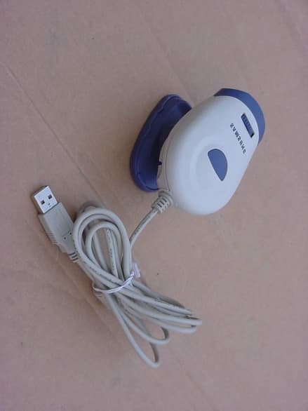
PFBSRE06002
Jan 21, 2002USB PC Camera
Equipment Class
JBP - Part 15 Class B Computing Device Peripheral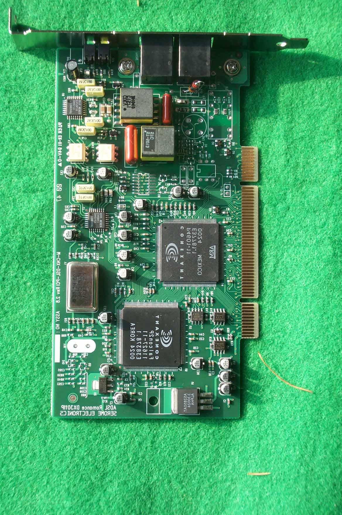
PFBM-CNX-DSL-PCI2
Jan 04, 2001ADSL Modem
Equipment Class
JBP - Part 15 Class B Computing Device Peripheral