PG8KW101TWireless PC Lock
Keymark Technology Co Ltd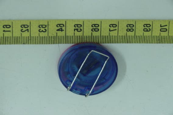
Click to zoom
Application Details
- Equipment Class
- DSC - Part 15 Security/Remote Control Transmitter
- Date of Grant
- Dec 22, 2003
- Application Purpose
- Original Equipment
- Date of Application
- Dec 22, 2003
- Equipment Note
- Wireless PC Lock
- Frequency Range
- 315.00000000 - 315.00000000
- Company
- Keymark Technology Co Ltd
- Country
- Taiwan
Documents & Files
Document Text
Text extracted from the exhibit documents filed with the FCC. Open a document above to read the original.
Users Manual
II. Hardware Hardware Installation ............................... 2 Hardware Removal .................................. 3 III. Software Software Installation ................................. 3 Automatic Installation ................................ 3 Password Setting ..................................... 4 Product ID Recognition .............................. 5 Software Removal ..................................... 6 IV. User Guide ............................................... 7 V. Frequently Asked Questions ....................... 10 VI. Technical Support and Service ..................... Model : Wireless PC Lock Accessories : 1. Transmitter unit × 1 / Receiver unit × 1 2. 3V (CR2032) Battery × 1 3. Driver CD × 1 Function : 1. The computer automatically enters “ Lock Mode ” when the user is away from computer by more than 2 meters 2. The computer automatically resumes normal operation when the user is back to within 2 meters range 3. Once the computer enters the “ Lock Mode ” a password is required to use the computer if the transmitter/receiver pair is not available to unlock the computer 4. One transmitter can be shared with several computers 5. The computer will signal “ Warning ” when battery voltage of the transmitter is too low Specifications : 1. One unique “ Security Code ” in the Transmitter Computer automatically recognizes the code itself 2. A maximum of 5 sets of “ Password ” and each set allows maximum of 125 numbers/characters (case insensitive) 3. Operation frequencies: □ FCC/315MHz;□ CE/434MHz 4. Transmitter Power Supply: DC 3V 5. Battery Usage: approximately 2000 hours 6. Receiver Power Supply: DC 5V, provided by the computer through USB port 7. Software Driver: support Windows 98 SE / ME / 2000 / XP Hardware Installation A. Insert the Wireless PC Lock receiver into the USB port and the computer will automatically detect and determine if the hardware is properly installed. B. If computer fails to detect the receiver device after the hardware installation, the following window will display on the screen. Click the “ Exit “ button and repeat the above step again. 第 2 頁,共 10 頁Table of Contents 2003/10/30file://C:\tmp\安規\SEND\FOR%20FCC\Eng\ENG.htm C. If the following window is displayed on the screen, click the “ OK “ button to cancel the installation. ** Please double check to see if (a) the USB port is fully functional, and (b) the Wireless PC Lock receiver is properly inserted into the USB port. Software Installation Automatic Installation Place the driver software CD which comes with the Wireless PC Lock in the CD-ROM driver and the computer will automatically read and execute the installation program. The computer screen will look similar to the one below. To install the software, simply follow the on-screen instructions. Click the “ OK “ button to start the installation. 第 3 頁,共 10 頁Table of Contents 2003/10/30file://C:\tmp\安規\SEND\FOR%20FCC\Eng\ENG.htm When the software is installing, the computer screen will look similar to the one below. Once the software installation is completed, click the “ OK “ button. 第 4 頁,共 10 頁Table of Contents 2003/10/30file://C:\tmp\安規\SEND\FOR%20FCC\Eng\ENG.htm Password Setting After the software driver installation is completed, the screen will look similar to the picture below. Please set at least one valid password. The Wireless PC Lock software accommodates a maximum of five (5) sets of passwords with up to 125 alpha-numeric characters in each password. Please note that the alpha-numeric characters in each password are case insensitive. In the pull-down menu of the password setting screen, you may choose a Password Reminder or leave it blank. If a color key is chosen as the Password Reminder , please note that only White, Cyan, Red, Magenta, Yellow, Black, Green, and Blue colors are available. Product ID Recognition An ID recognize procedure must be completed prior to using the product. Recognize Procedure: (a) Please make sure the transmitter is turned off. (b). After the password is successfully set, the following window will display on the screen indicating that the recognition is in progress. The transmitter may now be turned on. (c) The following pop-window indicates that the ID recognize process is complete. If the time limit is exceeded during the recognition process, a warning window will pop-up as shown in the following illustration. To proceed, click the “ Rerecognize “ button to retry the recognition right away or the “ Cancel “ button to try again later. 第 5 頁,共 10 頁Table of Contents 2003/10/30file://C:\tmp\安規\SEND\FOR%20FCC\Eng\ENG.htm ** Causes for exceeding time limit: ** Actions: 1. Transmitter is off Turn on transmitter and make sure its LED blinks 2. More than two transmitters nearby Follow recognize procedure to re-recognize 3. Off air RF interference Move transmitter closer to receiver until receiver’s LED blinks Software Removal There are two ways to uninstall the Wireless PC Lock software: 1. Click the Start button, select the All Programs menu button, and then select the Uninstall option in the Wireless PC Lock menu. 2. Click the Start button, select the Control Panel menu button, click the Add or Remove Programs icon, and then select the Window PC Lock program in the Add/Remove menu. l 第 6 頁,共 10 頁Table of Contents 2003/10/30file://C:\tmp\安規\SEND\FOR%20FCC\Eng\ENG.htm User’s Guide 1. The following taskbar icon indicates normal operation mode. 2. The following taskbar icon indicates computer lock-down mode. ** Lock -down mode : a. When the user walks away from the computer beyond the effective distance threshold, The receiver loses the transmitter signal and thus the computer enters lock-down mode. b. The transmitter under turn – off status. 3. Use the right button of mouse to open the context sensitive menu to select the ID Recognize, Emergency Rescue, Manual Lock, Force Lock, Help and About functions. a. ID Recognize : ID Recognize is required every time a new transmitter is used. 第 7 頁,共 10 頁Table of Con…
Text truncated - open the document above for the full version.
Cover Letter(s)
1 Mike Kuo From: S. S. Liou [[email protected]] Sent: December192003Friday 2:29 AM To: Mike Kuo Subject: Re: Keymark Technology Co., Ltd., FCC ID:PG8KW101T, AN03T3463 Exhibit-C-Test_Rep ort_revised.... Exhibit-G-Circuit-Dia gram_revi... Exhibit-A-Block_Dia gram_revise... Dear Mike, Ans. #1, this transmitter is always in transmitting mode. The duration of each transmission is 75ms and the silent period between transmissions is 12 seconds. This operation complys with the requirement of 15.231(e). Please refer to revised test report. The radiated emission has been retested. In order to comply with 15.231(e), the resistor R10 has been changed from 220K ohm to 330K ohm. Please refer to revised schematic diagram and block diagram. Ans. #2, the schematic diagram is attached. Best regards, ================================ S. S. Liou Engineer / EMC Dep. II ETC ----- Original Message ----- From: "Mike Kuo" <[email protected]> To: "ETC/Iris (E-mail)" <[email protected]>; "Liou, S. S. (E-mail)" <[email protected]> Sent: Wednesday, December 17, 2003 6:15 AM Subject: FW: Keymark Technology Co., Ltd., FCC ID:PG8KW101T, AN03T3463 > > > -----Original Message----- > From: CERTADM > Sent: Tuesday, December 16, 2003 2:15 PM > To: Mike Kuo > Subject: Keymark Technology Co., Ltd., FCC ID:PG8KW101T, AN03T3463 > > > Notice_content > ------------- > Question #1: This device was tested per 15.231(b) technical requirement. In > the operation description nor in the test report provide technical > information to show how the device comply with 15.231(a) periodical > transmission. Since this device will turn on the receiver when the > transmitter is within 2 meter from the receiver, the transmitter is always > in the transmitting mode. Please provide detail technical information to > address periodical transmission requirement. > > Question #2: Please provide schematic diagram. > > Best Regards > > Mike Kuo > The items indicated above must be submitted before processing can continue > on the above referenced application. Failure to provide the requested > information within 30 days of the original e-mail date may result in 2 > application dismissal and forfeiture of the filing fee. Also, please note > that partial responses increase processing time and should not be submitted. > Any questions about the content of this correspondence should be directed to > the e-mail address listed below the name of the sender.
External Photos
ETC Report No.:ET92R-10-073-04 FCC ID.: PG8KW101T Rev. No 1.0 CONSTRUCTED PHOTOS of EUT Top View of EUT Top View of EUT
ID Label/Location Info
12 mm 3mm
Internal Photos
ETC Report No.:ET92R-10-073-04 FCC ID.: PG8KW101T Rev. No 1.0 CONSTRUCTED PHOTOS of EUT Internal View of EUT ETC Report No.:ET92R-10-073-04 FCC ID.: PG8KW101T Rev. No 1.0 CONSTRUCTED PHOTOS of EUT Component View of Main PCB 4..Solder View of Main PCB
Test Report
Rev. No 1.0 FCC Part 15 EMI TEST REPORT of E.U.T. : Wireless PC Lock FCC ID. : PG8KW101T MODEL : KW-101 Working Frequency : 315 MHz for APPLICANT : Keymark Technology Co., Ltd. ADDRESS : 10F, No. 123-1, Shing De Rd., San Chung City, Taipei Hsien, Taiwan R.O.C. Test Performed by ELECTRONICS TESTING CENTER, TAIWAN NO. 34, LIN 5, DING FU TSUN, LINKOU HSIANG TAIPEI HSIEN, TAIWAN, R.O.C. Tel:(02)26023052 Fax:(02)26010910 http://www.etc.org.tw ; e-mail : [email protected] Report Number : ET92R-10-073-04 ETC Report No.:ET92R-10-073-04 FCC ID.: PG8KW101T Rev. No 1.0 TEST REPORT CERTIFICATION Applicant : Keymark Technology Co., Ltd. 10F, No. 123-1, Shing De Rd., San Chung City, Taipei Hsien, Taiwan R.O.C. Manufacturer : Keymark Technology Co., Ltd. 10F, No. 123-1, Shing De Rd., San Chung City, Taipei Hsien, Taiwan R.O.C. Description of EUT : a) Type of EUT : Wireless PC Lock b) Trade Name : Keymark c) Model No. : KW-101 d) FCC ID : PG8KW101T e) Working Frequency : 315 MHz f) Power Supply : DC 3V Regulation Applied : FCC Rules and Regulations Part 15 Subpart C (2002) I HEREBY CERTIFY THAT; The data shown in this report were made in accordance with the procedures given in ANSI C63.4 and the energy emitted by the device was founded to be within the limits applicable. I assume full responsibility for accuracy and completeness of these data. Note : 1. The results of the testing report relate only to the items tested. 2. The testing report shall not be reproduced except in full, without the written approval of ETC. Issued Date : Nov. 05, 2003 Test Engineer : ( Kevin Lee ) Approve & Authorized Signer : Will Yauo, Manager EMC Dept. II of ELECTRONICS TESTING CENTER, TAIWAN ETC Report No.:ET92R-10-073-04 FCC ID.: PG8KW101T Rev. No 1.0 Table of Contents Page 1. GENERAL INFORMATION.....................................................................................................................................................1 1.1 PRODUCT DESCRIPTION...........................................................................................................................................................1 1.2 CHARACTERISTICS OF DEVICE:...............................................................................................................................................1 1.3 TEST METHODOLOGY..............................................................................................................................................................1 1.4 TEST FACILITY..........................................................................................................................................................................1 2. DEFINITION AND LIMITS.......................................................................................................................................................2 2.1 DEFINITION................................................................................................................................................................................2 2.2 RESTRICTED BANDS OF OPERATION.....................................................................................................................................2 2.3 LIMITATION...............................................................................................................................................................................2 2.4 LABELING REQUIREMENT.......................................................................................................................................................4 2.5 USER INFORMATION.................................................................................................................................................................4 3 SYSTEM TEST CONFIGURATION.........................................................................................................................................5 3.1 JUSTIFICATION..........................................................................................................................................................................5 3.2 DEVICES FOR TESTED SYSTEM...............................................................................................................................................5 4. RADIATED EMISSION MEASUREMENT.............................................................................................................................6 4.1 APPLICABLE STANDARD.........................................................................................................................................................6 4.2 MEASUREMENT PROCEDURE..................................................................................................................................................6 4.3 TEST DATA.................................................................................................................................................................................8 4.3.1 Tx Fundamental and Harmonics..................................................................................................................................8 4.3.2 Other Emissions...............................................................................................................................................................9 4.4 FIELD STRENGTH CALCULATION........................................................................................................................................10 4.5 ACTIVATE TIME......................................................................................................................................................................10 4.6 CALCULATION OF DUTY FACTOR.......................................................................................................................................10 4.7 RADIATED TEST EQUIPMENT....................................................................................................................…
Text truncated - open the document above for the full version.
Test Setup Photos
ETC Report No.:ET92R-10-073-04 FCC ID.: PG8KW101T Rev. No 1.0 Radiated Measurement Photos
Contact Information
Applicant
C. C. Yang(R&D Engineer)
Test Firm
Electronics Testing Center, TaiwanWin-Po Tsai
Technical Specifications
| # | Rule Parts | Frequency Range | Power Output |
|---|---|---|---|
| 1 | 15.231(e) | 315 MHz - 315 MHz | - |
Other Applications from Keymark Technology Co Ltd
PG8AR103TR
Sep 06, 2005Mini Wallet Alarm
Equipment Class
DSC - Part 15 Security/Remote Control Transmitter
PG8MT01A
Nov 11, 2004Music Transmitter
Equipment Class
DXX - Part 15 Low Power Communication Device Transmitter
PG8101T01
Jun 02, 2002Security Transmitter ( Reminder )
Equipment Class
DSC - Part 15 Security/Remote Control Transmitter
PG8101E01
Oct 31, 2001Wireless HandFree- Ear Set
Equipment Class
DXT - Part 15 Low Power Transceiver, Rx Verified
PG8101H01
Oct 31, 2001Wireless HandFree- Hand Set
Equipment Class
DXT - Part 15 Low Power Transceiver, Rx Verified