PG8MT01AMusic Transmitter
Keymark Technology Co Ltd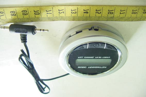
Click to zoom
Application Details
- Equipment Class
- DXX - Part 15 Low Power Communication Device Transmitter
- Date of Grant
- Nov 11, 2004
- Application Purpose
- Original Equipment
- Date of Application
- Nov 11, 2004
- Equipment Note
- Music Transmitter
- Frequency Range
- 88.10000000 - 107.90000000
- Company
- Keymark Technology Co Ltd
- Country
- Taiwan
Documents & Files
Document Text
Text extracted from the exhibit documents filed with the FCC. Open a document above to read the original.
Users Manual
910805 7 User’s Manual: Setup Instructions : There are three keys no the Music Transmitter. Press thebutton of represents the power on/off . The symbol represent the channel selecting decreasingly or increasingly - (1) Remove the battery cover from the back of the Music Transmitter by gently pressing down the tab and pulling out. Install batteries into the holder then replace the cover (2) Power the Music Transmitter (LCD will light up when powered properly) (3) Turn on the radio and select the FM frequency in the range of 88.1~107.9MHz (4) Tune your Music Transmitter to the FM frequency as selected in step #3 (5) Plug stereo cable into the lineout jack of the audio source player (6) Adjust the volume on your audio source player and target radio for best enjoyment This device complies with part 15 of the FCC Rules. Operation is subject to the following two conditions: 1. This device may not cause harmful interference. 2. This device must accept any interference received, including interference that may cause undesired operation. Specifications : * Modulation : FM Stereo Modulation * Selectable Frequencies : 88.1~107.9MHz * Audio Connector : both 2.5mm and 3.5mm Stereo Plugs * Power Requirement for DC input jack : DC IN 6V * Power Requirement : 3 pieces of “AAA” standard battery or “AAA” rechargeable battery * Current consumption : 25mA * Signal Distortion : Less than 0.5% * Frequency Response : 50Hz to 15KHz * Size : 63 910805 8 * Weight : 124g Important information : l The product may be diminished by environmental conditions such as walls, metal objects, relative humidity and other radio signals. l Keep this product away from water and avoid been crashed. Trouble shooting : l Change the battery as soon as possible when LCD did not goes on. l Check for any nearby source of interference. Try to get rid of it or move away from the source. l If none of the above works, return unit to factory as per warranty. Do not attempt to repair it by yourself. Notice : The changes or modifications not expressly approved by the party responsible for compliance could void the user’s authority to operate the equipment.
Cover Letter(s)
1 Helen Zhao Subject:FW: Keymark Technology Co., Ltd., FCC ID: PG8MT01A, Assessment NO.: AN04T4274, Notice#1 -----Original Message----- From: SS Sent: Thursday, November 11, 2004 10:21 PM To: Helen Zhao Cc: R00/??? Subject: Re: Keymark Technology Co., Ltd., FCC ID: PG8MT01A, Assessment NO.: AN04T4274, Notice#1 > > Dear Helen, > > Attached please find revised test report and product photos. > > Best regards, > > S. S. Liou > Engineer / EMC Dept. II > Electronics Testing Center, Taiwan > > ----- Original Message ----- > From: "Helen Zhao" <[email protected]> > To: "SS" > Sent: Tuesday, November 09, 2004 3:25 AM > Subject: RE: Keymark Technology Co., Ltd., FCC ID: PG8MT01A, Assessment NO.: AN04T4274, Notice#1 > > > > Dear SS, > > > > #1: As you indicated in your reply, the radiated emission test was done > when the device was powered by AC/DC power adaptor. In this case, you need > to do power line conducted emission test. Please provide LC test data. (It's > interesting you did include LC test photos in the setup photos, but claimed > LC is not applicale in the test report.) > > > > Thank you, > > Helen > > > > -----Original Message----- > > From: SS > > Sent: Sunday, November 07, 2004 11:41 PM > > To: Helen Zhao > > Cc: Mike Kuo; iris > > Subject: Re: Keymark Technology Co., Ltd., FCC ID: PG8MT01A, Assessment > > NO.: AN04T4274, Notice#1 > > > > > > Dear Helen, > > 2 > > Replying your questions. > > > > #1 Please refer to revised test report. The misleading information about > > IPod and USB cables were deleted. The EUT is a FM transmitter. A signal > > generator is used during test. As to the setup photos shows the > > transmitter was connected with one line down to the floor, that was the power cord > > of AC/DC power adapter. > > > > #2 Please refer to revised test report. The test of middle channel 98MHz > was provided. > > > > #3 Please refer to revised test report. > > > > #4 and #5 Please refer to revised user manual. The information of IPod > and USB cables are misleading. They are not relative to the EUT. > > #6 The bandedge plots is intended for proving the compliance of 15.239(a). The > > transmission will lie wholly within the frequency range of 88-108 MHz. The > > measurement has done in short distance for the advantage of higher emission > > level. For protecting the measuring equipment, a suitable attenuator was used. > > Best regards, > > > > S. S. Liou > > Engineer / EMC Dept. II > > Electronics Testing Center, Taiwan > > > > ----- Original Message ----- > > From: "iris" <[email protected]> > > To: "R00/???" <[email protected]> > > Sent: Monday, November 01, 2004 4:14 PM > > Subject: Fw: Keymark Technology Co., Ltd., FCC ID: PG8MT01A, Assessment > NO.: > > AN04T4274, Notice#1 > > > > > > -----Original Message----- > > > > From: Compliance Certification Services [mailto:[email protected]] > > > > Sent: Friday, October 22, 2004 2:53 PM > > > > To: Helen Zhao > > > > Subject: Keymark Technology Co., Ltd., FCC ID: PG8MT01A, Assessment > NO.: AN04T4274, Notice#1 > > > > > > > > Question #1: The test report indicates that "Devices of Tested > > > > System" consists of music transmitter (1.2m single line, 1.2m USB cable *2) > > > > and IPod, but either the test setup photos or test report does not > > > > clearly explain how the test was setup, the setup photos do not show IPod, > > > > the transmitter was connected with one line down to the floor, what is > > > > that for? From the test setup photos, it seems the signal generator was used > > > > for testing. Why was it not included in the equipment list? Please provide > > > > test setup diagram and I/O cable list to clearly explain how the test was > > > > conduced. > > > > > > > > Question #2: The test report shows the radiated emission test was > > > > done at 98MHz as middle channel, but the bandedge test was done at 89MHz as > > > > middle channel. Please explain. > > > > > > > > Question #3: The radiated emission test data on the test report do not > > > > indicate clearly it is peak value or average value. Note 2 under the test > > > > data said "Mark "***" means that Peak result is meet average limit. But 3 > > > > there is no "***" ever marked. Based upon FCC15.35, the device needs to > > > > comply with both average and peak limits. > > > > > > > > Question #4: The 1-page user manual does not mention any accessories the > > > > music transmitter will come with, if as test report indicated, 1.2m single > > > > line, 1.2m USB cable *2 will be provided to the end user, please include > > > > the application instruction. > > > > > > > > Question #5: The user manual does not include User Information to > > > > satisfy FCC15.21 requirement. Please revise the user manual. > > > > > > > > Question #6: The bandedge plots show at 88.1MHz and 107.9MHz, the > > > > fundamental field strength is way above the peak limit (68dBuv/m). Please explain. > > > > > > > > Best regards, > > > > Helen Zhao > > > > > > > > The items indicated above must be submitted before processing can continue > > > > on the above referenced application. Failure to provide the requested > > > > information within 30 days of the original e-mail date may result in > > > > application dismissal and forfeiture of the filing fee. Also, please > > > > note that partial responses increase processing time and should not be > > > submitted. > > > > Any questions about the content of this correspondence should be directed to > > > > the e-mail address listed below the name of the sender.
External Photos
ETC Report No.:ET93R-08-059 Sheet 1 of 7 Sheets FCC ID.: PG8MT01A Rev. No 1.0 CONSTRUCTED PHOTOS of EUT 1. Top View of EUT 2. Rear View of EUT ETC Report No.:ET93R-08-059 Sheet 2 of 7 Sheets FCC ID.: PG8MT01A Rev. No 1.0 CONSTRUCTED PHOTOS of EUT 3. Side View of EUT 4. Side View of EUT ETC Report No.:ET93R-08-059 Sheet 5 of 7 Sheets FCC ID.: PG8MT01A Rev. No 1.0 CONSTRUCTED PHOTOS of EUT 8. Front View of Adaptor 9. Rear View of Adaptor
ID Label/Location Info
LABEL Back View This statement will be placed in User’s Manual: This device complies with part 15 of the FCC Rules. Operation is subject to the following two conditions: 1. This device may not cause harmful interference. 2. This device must accept any interference received, including interference that may cause undesired operation. FCC ID: PG8MT01A FCC ID: PG8MT01A
Internal Photos
ETC Report No.:ET93R-08-059 Sheet 3 of 7 Sheets FCC ID.: PG8MT01A Rev. No 1.0 CONSTRUCTED PHOTOS of EUT 5. Internal View of EUT ETC Report No.:ET93R-08-059 Sheet 4 of 7 Sheets FCC ID.: PG8MT01A Rev. No 1.0 CONSTRUCTED PHOTOS of EUT 6. Component View of PCB 7. Solder View of PCB ETC Report No.:ET93R-08-059 Sheet 6 of 7 Sheets FCC ID.: PG8MT01A Rev. No 1.0 CONSTRUCTED PHOTOS of EUT 10. Internal View of Adaptor ETC Report No.:ET93R-08-059 Sheet 7 of 7 Sheets FCC ID.: PG8MT01A Rev. No 1.0 CONSTRUCTED PHOTOS of EUT 11. Component View of Adaptor’s PCB 12. Solder View of Adaptor’s PCB
Operational Description
ETC Report No.:ET93R-08-059 Sheet 1 of 33 Sheets FCC ID.: PG8MT01A Rev. No 1.0 1. GENERAL INFORMATION 1.1 Product Description a) Type of EUT : Music Transmitter b) Trade Name : Keymark c) Model No. : MT-01 d) Working Frequency : 88.1~107.9 MHz e) Power Supply : DC 3V 1.2 Characteristics of Device: 1. Frequency: 88.1~107.9 MHz 2. Modulation: FM Stereo Modulation 1.3 Test Methodology Both conducted and radiated testing was performed according to the procedures in chapter 13 of ANSI C63.4. The Music Transmitter under test was operated in its normal operating mode for the purpose of the measurements. The receiving antenna polarized horizontally was varied from 1 to 4 meters and the wooden turntable was rotated through 360 degrees to obtain the highest reading on the field strength meter or on the display of the spectrum analyzer. And also, each emission was to be maximized by changing the orientation of the Music Transmitter under test. 1.4 Test Facility The open area test site and conducted measurement facility used to collect the radiated data is located on the roof top of Building at No. 34, Lin 5, Ding Fu Tsun, Linkou Hsiang, Tapei Hsien, Taiwan 244, R.O.C.. This site has been fully described in a report submitted to your office, and accepted in a letter dated Feb. 10, 2000.
Test Report
Rev. No 1.0 FCC Part 15 Subpart C TEST REPORT of E.U.T. : Music Transmitter FCC ID. : PG8MT01A MODEL : MT-01 Working Frequency : 88.1~107.9 MHz for APPLICANT : Keymark Technology Co., Ltd. ADDRESS : 10F, No. 123-1, Shing De Rd., San Chung City, Taipei Hsien, Taiwan, R.O.C. Test Performed by ELECTRONICS TESTING CENTER, TAIWAN NO. 34, LIN 5, DING FU TSUN, LINKOU HSIANG, TAIPEI HSIEN, TAIWAN, R.O.C. http://www.etc.org.tw ; e-mail : [email protected] Tel:(02)26023052 Fax:(02)26010910 Report Number : ET93R-08-059 ETC Report No.:ET93R-08-059 FCC ID.: PG8MT01A Rev. No 1.0 TEST REPORT CERTIFICATION Applicant : Keymark Technology Co., Ltd. 10F, No. 123-1, Shing De Rd., San Chung City, Taipei Hsien, Taiwan, R.O.C. Manufacturer : Keymark Technology Co., Ltd. 10F, No. 123-1, Shing De Rd., San Chung City, Taipei Hsien, Taiwan, R.O.C. Description of EUT : a) Type of EUT : Music Transmitter b) Trade Name : Keymark c) Model No. : MT-01 d) Working Frequency : 88.1~107.9 MHz e) Power Supply : 120VAC 60Hz. Output: 6VDC 300mA Regulation Applied : FCC Rules and Regulations Part 15 Subpart C (2003) I HEREBY CERTIFY THAT; The data shown in this report were made in accordance with the procedures given in ANSI C63.4 and the energy emitted by the device was founded to be within the limits applicable. I assume full responsibility for accuracy and completeness of these data. Issued Date : Oct. 15, 2004 Test Engineer : ( Bo-Sen Fu ) Approve & Authorized Signer : Will Yauo, Manager EMC Dept. II of ELECTRONICS TESTING CENTER, TAIWAN ETC Report No.:ET93R-08-059 FCC ID.: PG8MT01A Rev. No 1.0 Table of Contents Page 1 GENERAL INFORMATION....................................................................................................1 1.1 Product Description....................................................................................................................1 1.2 Characteristics of Device.............................................................................................................1 1.3 Test Methodology.......................................................................................................................1 1.4 Test Facility................................................................................................................................1 2 DEFINITION AND LIMITS.....................................................................................................2 2.1 Definition....................................................................................................................................2 2.2 Restricted Bands of Operation.....................................................................................................2 2.3 Limitation....................................................................................................................................2 2.4 Labeling Requirement..................................................................................................................3 2.5 User Information.........................................................................................................................3 3 SYSTEM TEST CONFIGURATION........................................................................................4 3.1 Justification.................................................................................................................................4 3.2 Devices for Tested System..........................................................................................................4 4 RADIATED EMISSION MEASUREMENT...........................................................................5 4.1 Applicable Standard....................................................................................................................5 4.2 Measurement Procedure.............................................................................................................5 4.3 Measuring Instrument..................................................................................................................7 4.4 Test Data....................................................................................................................................8 4.5 Field Strength Calculation..........................................................................................................12 4.6 Radiated Measurement Photos..................................................................................................13 5 CONDUCTED EMISSION MEASUREMENT.....................................................................14 5.1 Standard Applicable..................................................................................................................14 5.2 Measurement Procedure...........................................................................................................14 5.3 Conducted Emission Data.........................................................................................................15 5.4 Result Data Calculation.............................................................................................................17 5.5 Conducted Measurement Equipment.........................................................................................17 5.6 Photos of Conduction Measuring Setup.....................................................................................18 6 ANTENNA REQUIREMENT.................................................................................................19 6.1 Standard Applicable..................................................................................................................19 6.2 Antenna Construction................................................................................................................19 7 EMISSION BAND MEASUREMENT..................................................................................20 7.1 Standard Applicable.....................................................................…
Text truncated - open the document above for the full version.
Test Setup Photos
ETC Report No.:ET93R-08-059 Sheet 13 of 33 Sheets FCC ID.: PG8MT01A Rev. No 1.0 4.6 Radiated Measurement Photos ETC Report No.:ET93R-08-059 Sheet 18 of 33 Sheets FCC ID.: PG8MT01A Rev. No 1.0 5.6 Photos of Conduction Measuring Setup
Contact Information
Applicant
C. C. Yang(R&D Engineer)
Test Firm
Electronics Testing Center, TaiwanWill Yauo
Technical Specifications
| # | Rule Parts | Frequency Range | Power Output |
|---|---|---|---|
| 1 | 15C | 88.1 MHz - 107.9 MHz | - |
Other Applications from Keymark Technology Co Ltd
PG8AR103TR
Sep 06, 2005Mini Wallet Alarm
Equipment Class
DSC - Part 15 Security/Remote Control Transmitter
PG8KW101T
Dec 22, 2003Wireless PC Lock
Equipment Class
DSC - Part 15 Security/Remote Control Transmitter
PG8101T01
Jun 02, 2002Security Transmitter ( Reminder )
Equipment Class
DSC - Part 15 Security/Remote Control Transmitter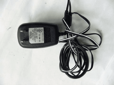
PG8101E01
Oct 31, 2001Wireless HandFree- Ear Set
Equipment Class
DXT - Part 15 Low Power Transceiver, Rx Verified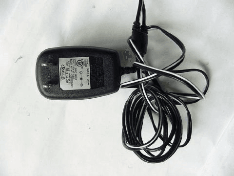
PG8101H01
Oct 31, 2001Wireless HandFree- Hand Set
Equipment Class
DXT - Part 15 Low Power Transceiver, Rx Verified