PGAM6200Wireless RF Host Transceiver
American Microsystems, Ltd.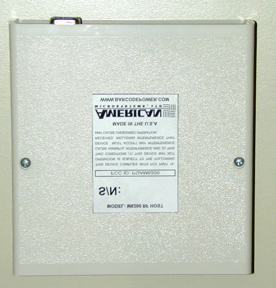
Click to zoom
Application Details
- Equipment Class
- DXT - Part 15 Low Power Transceiver, Rx Verified
- Date of Grant
- Feb 20, 2001
- Application Purpose
- Original Equipment
- Date of Application
- Feb 20, 2001
- Equipment Note
- Wireless RF Host Transceiver
- Frequency Range
- 916.50000000 - 916.50000000
- Company
- American Microsystems, Ltd.
- Country
- United States
Documents & Files
Document Text
Text extracted from the exhibit documents filed with the FCC. Open a document above to read the original.
Users Manual
Model 6200 RF Host & Model 6300 USB RF Host USER’S MANUAL AMERICAN MICROSYSTEMS, LTD. 2190 Regal Parkway • •• • Euless, TX 76040 (817)571-9015 • •• • (800)648-4452 • •• • Fax: (817)685-6232 www.barcodepower.com 1 FCC NOTICE NOTE: This equipment has been tested and found to comply with the limits for a Class B digital device, pursuant to Part 15 of the FCC Rules. These limits are designed to provide reasonable protection against interference in a residential installation. This equipment generates, uses, and can radiate radio frequency energy and, if not installed and used in accordance with the instruction manual, may cause interference to radio communications. However, there is no guarantee that interference will not occur in a particular installation. If this equipment does cause interference to radio or television reception, which can be determined by turning the equipment off and on, the user is encouraged to try to correct the interference by one or more of the following measures: -- Reorient or relocate the receiving antenna. -- Increase the separation between the equipment and the receiver. -- Connect the equipment into an outlet on a circuit different from that to which the receiver is connected. -- Consult the dealer or an experienced radio/TV technician for help. There are no user-serviceable internal parts. Changes or modifications not expressly performed by the manufacturer will void the manufacturer’s warranty and may void the user’s legal authority to operate the equipment. FCC PRODUCT LABEL INFORMATION This device complies with FCC Part 15. Operation is subject to the following two conditions: (1) this device may not cause harmful interference and (2) this device must accept any interference received, including interference that may cause undesired operation. TRADEMARK ACKNOWLEDGEMENTS IBM, AT/XT, and PS/2 are registered trademarks of International Business Machines Corporation. MS-DOS, Windows, and Notepad are trademarks of Microsoft Corporation. PSC and Quickscan 6000 (QS6000) are trademarks of PSC Corporation. Metrologic MS-941 Laser is a trademark of Metrologic Instruments, Inc. All other trademarks or registered trademarks of other companies are used only for explanation without intent to infringe. © Copyright American Microsystems, Ltd. 2000. All rights reserved. 2 TABLE OF CONTENTS Introduction 3 Features 3 Setup Instructions 4 Usage Guidelines 6 Setting the Host ID 7 Default Settings 8 Changing the Settings 10 Programming Guide 12 Code 39 14 UPC 15 EAN 16 UPC/EAN Supplements 17 Interleaved 2 of 5 18 Codabar 19 Code 128 20 Code 93 20 MSI/Plessey 21 Code 11 22 Preamble 23 Postamble 24 Barcode Options 25 Barcode Edit 27 Laser/CCD Options 28 Termination Character 28 Scan Beep Length & Tone 29 Diagnostics 29 Signal Definitions 30 Extended ASCII Keyboard Mapping 31 3 INTRODUCTION Together with the Model 6000 RF Barcode Reader (M6000), the Model 6200 RF Host (M6200) or the Model 6300 USB RF Host (M6300) provide the user with the means of converting an undecoded laser, CCD, or wand into a wireless device. By allowing many types of input devices, this system provides users the ability to customize according their needs and is an affordable alternative to purchasing an integrated RF system. The M6200/M6300 RF Host is used as a companion to the M6000, receiving the RF data and converting it into useable IBM compatible PC keyboard data. For an AT or PS/2 PC keyboard interface, the Model 6200 RF Host (M6200) is used. For an USB keyboard interface, the Model 6300 USB RF Host (M6300) is used. The M6200/M6300 RF Host also features a barcode scanner interface, allowing it to function locally as a decoder for laser, CCD, and wand devices, in addition to its normal function of receiving and converting RF data. The M6200/M6300 RF Host can be custom configured using the M6000/M6200/M6300 Setup Menu Sheet to allow multiple RF Hosts, as well as, other standard options that allow the equipment to be tailor-fitted for your individual data collection application. Reliability, ease of use, and affordability make American Microsystems’ M6000 RF Barcode Reader System an excellent choice for wireless barcode data collection. FEATURES • Expandable: Allows ten (10) M6000 RF Portables per RF Host, by setting the Portable ID. The total system allows up to eight (8) RF Hosts to be used, by setting the Host ID. • Reader automatically recognizes and reads the following barcode types: -Code 39 -Codabar -Extended Code 39 (full ASCII) -Code 128 -Interleaved 2 of 5 -Code 93 -UPC-A, UPC-E -Code 11 -EAN-8, EAN-13 -MSI/Plessey -UPC & EAN supplements (2 and 5 character) • Supports any low cost 5 Volt undecoded laser, CCD, or wand devices. 4 SETUP INSTRUCTIONS M6200 RF Host: AT and PS/2 Keyboard Connection Step 1: Turn OFF power to the computer. Step 2: Unplug the keyboard connector from the back of the computer. Note the style of the connector. If the connector is 1/2” in diameter and has five (5) pins in a semicircle configuration, then the connector is AT style. If the connector is 3/8” in diameter, then it is the PS/2 style. The keyboard will be one of these two styles. The two supplied AT to PS/2 converters can be used to match the style of your keyboard. Step 3: Locate the supplied “wedge” cable. This cable is black, and has a male DB9 connector at one end and on the other end has a keyboard receptacle (to plug in your keyboard) and a keyboard plug (to plug into your computer). Step 4: The next step is to connect the “wedge” cable to the M6200’s keyboard interface, the female DB9 connector, and then secure it using the two finger screws. Step 5: Plug the keyboard into the keyboard receptacle of the “wedge” cable. Use the supplied AT to PS/2 converter, if needed, to match your style of keyboard. A keyboard must be used with the M6200 for the “wedge” interface to function. Step 6: Plug the keyboard plug of the “wedge” cable into the keyboard port of the computer. Use the supplied AT to PS/2 converter, if ne…
Text truncated - open the document above for the full version.
Block Diagram
American Microsystems, Ltd. 2190 Regal Parkway Euless, TX 76040 (817) 571-9015 M6200 Product Operation: American Microsystems’ M6200 is the host receiver for the companion M6000 wireless barcode decoder. This system provides a means of wireless transmission of barcode data and then of receiving this data from the M6200 host as simulated keyboard keystrokes (“wedge”) to an IBM compatible PC. The intended uses for this product include point-of-sale and inventory applications in a business or industrial environment. The M6200 consists an Atmel ATMega103 microcontroller operating at 4 MHz, a voltage regulator for RF power, an interface for connecting an undecoded barcode reading device (e.g. laser, wand, or CCD), an IBM PC compatible keyboard wedge interface, and finally of an RF Monolithics TR1000 radio frequency transceiver with a printed circuit board (PCB) based antenna. M6200 Block Diagram:
Cover Letter(s)
Andrew Perkins American Microsystems, Ltd. 2190 Regal Parkway Euless, TX 76040 Phone: (817) 571-9015 Fax: (817) 685-6232 Subject: Letter of Confidentiality Request for the M6200 Dear Reviewer, American Microsystems, Ltd. (AMS), requests that the Schematic exhibit of the application for FCC ID: PGAM6200 be withheld from routine availability for public inspection pursuant to Section 0.459 of the Commissions Rules and Freedom of Information Act (FOIA) Exemption 4, 5 U.S.C. 552 (b) (4). These particular exhibits consist of “trade secrets (or) commercial or financial information obtained from a person and privileged or confidential” 5 U.S.C 552 (b) (4), and is therefore entitled to protection from disclosure under the FOIA. The documents in question contain trade secrets: detailed technical descriptions, specifications, and schematics for a product offered for sale. This proprietary information would give AMS’s competitors an unearned competitive advantage. The documents contain “commercial information” within the scope of FOIA exemption 4. This information is the product of AMS’s investment of money, personnel, and other resources. The result of the investment is a fairly earned position in the marketplace. Premature release of the information threatens substantial and unwarranted harm to AMS’s competitive position. For these reasons, AMS has taken pains to keep this technical information confidential and intends to continue doing so. AMS customarily withholds rights to this information, granting access only to those who have a particular approved need for the information. AMS grants the Commission their needed access to these documents, but respectfully asks that the information be kept confidential. The filing fee that is required for this confidentiality request is included in the check that accompanies this application. If there are any questions about this request, please contact me. Thank you. Respectfully submitted, Andrew Perkins
Cover Letter(s)
Andrew Perkins American Microsystems, Ltd. 2190 Regal Parkway Euless, TX 76040 Phone: (817) 571-9015 Fax: (817) 685-6232 Attn: Reviewing Engineer Federal Communications Commission 7435 Oakland Mills Road Columbia, MD 21046 Subject: Letter of Agent Authorization for M6200 Dear Reviewer: American Microsystems, Ltd. (AMS) does hereby authorize MET Laboratories, Inc. to act in our behalf in all matters relating to equipment authorization for FCC ID: PGAM6200, and including the signing of all documents relating to these matters. We also hereby certify that no party to the application authorized hereunder is subject to the denial of benefits, including FCC benefits, pursuant to Section 5301 of the Anti-Drug Abuse Act of 1988, 21 U.S.C 853 (a). This agreement expires one year from the current date. If there are any questions about this request, please contact me. Thank you. Respectfully submitted, Andrew Perkins Date: 02/14/2001
External Photos
NTS Test Report No. A0579-6200-fcc National Technical Systems, Electromagnetic Compatibility Test ReportPage 12 of 17 1701 E. Plano Parkway Suite 150, Plano, TX 75074; Tel (972) 509-2566; Fax (972) 509-0073 5.0EMISSIONS The test procedures of Paragraph 2.1 were followed for these measurements. Conducted measurements were made in shielded enclosures. Radiated final measurements were made at the OATS facility described in Paragraph 2.0. All readings are quasi-peak unless otherwise stated and are listed in order of ascending delta. The original test data is contained in Master Job Folder A 0579, located at the National Technical Systems EMC Facility. Mode of operation is that listed under Paragraph 3.1, unless otherwise stated. 5.1Radiated Emissions 5.1.1Radiated Emissions Test Setup Top View of Equipment Under Test M6200 External Photo: FCC label location with FCC ID
ID Label/Location Info
M6200 External Photo: FCC label location with FCC ID
Internal Photos
M6200 Internal photo: Component side of PCB M6200 External Photo: FCC label location with FCC ID M6200 Internal Photo: Solder side of PCB
Operational Description
American Microsystems, Ltd. 2190 Regal Parkway Euless, TX 76040 (817) 571-9015 M6200 Product Operation: American Microsystems’ M6200 is the host receiver for the companion M6000 wireless barcode decoder. This system provides a means of wireless transmission of barcode data and then of receiving this data from the M6200 host as simulated keyboard keystrokes (“wedge”) to an IBM compatible PC. The intended uses for this product include point-of-sale and inventory applications in a business or industrial environment. The M6200 consists an Atmel ATMega103 microcontroller operating at 4 MHz, a voltage regulator for RF power, an interface for connecting an undecoded barcode reading device (e.g. laser, wand, or CCD), an IBM PC compatible keyboard wedge interface, and finally of an RF Monolithics TR1000 radio frequency transceiver with a printed circuit board (PCB) based antenna. M6200 Block Diagram:
Test Report
7 NTS Test Report No. A0579-6200-fcc rev1 Page 1 of 18 National 1701 E. Plano Pkwy Suite 150 Technical Plano, TX 75074 Systems Tel: 972-509-2566 Fax: 972-509-0073 Electromagnetic Compatibility (EMC) and Electrical Safety Test Report for Network Telecommunications Equipment For American Microsystems, AMERICAN MICROSYSTEMS’ M6200 FCC PART 15, SUB-PART B, CLASS B and FCC part 15.249 Prepared For:American Microsystems Prepared By:National Technical Systems 1701E. Plano Parkway Suit 150 Plano, TX 75074 Issued:February 19, 2001 This report and the information contained herein represent the results of testing test articles identified and selected by the client performed to specifications and/or procedures selected by the client. National Technical Systems (NTS) makes no representations, expressed or implied, that such testing is adequate (or inadequate) to demonstrate efficiency, performance, reliability, or any other characteristic of the articles being tested, or similar products. This report should not be relied upon as an endorsement or certification by NTS of the equipment tested, nor does it represent any statement whatsoever as to its merchantability or fitness of the test article, or similar products, for a particular purpose. This report shall not be reproduced except in full. NTS Test Report No. A0579-6200-fcc rev 1 National Technical Systems, Electromagnetic Compatibility Test ReportPage 2 of 18 1701 E. Plano Parkway Suite 150, Plano, TX 75074; Tel (972) 509-2566; Fax (972) 509-0073 Service For:American Microsystems Purchase Order No.:50799 This is to certify that the following report is true and correct to the best of my knowledge. _______________________________________________________________ John Ngo, Bob Stevens EMI Operations ManagerQuality Assurance Manager FCC, CE, Telecommunication NTS Test Report No. A0579-6200-fcc rev 1 National Technical Systems, Electromagnetic Compatibility Test ReportPage 3 of 18 1701 E. Plano Parkway Suite 150, Plano, TX 75074; Tel (972) 509-2566; Fax (972) 509-0073 TABLE OF CONTENTS 1.0GENERAL INFORMATION...................................................................................................................5 1.1PRODUCT DESCRIPTION.......................................................................................................................5 1.2INSTRUMENT CALIBRATION................................................................................................................5 1.2.1ACCURACY OF MEASUREMENT......................................................................................................6 1.3AMBIENT TESTS.....................................................................................................................................6 1.4FAILURE REPORTING..........................................................................................................................6 1.5THRESHOLD OF SUSCEPTIBILITY........................................................................................................6 1.6TEST PROGRAM DEVIATION................................................................................................................7 1.7INSPECTION.............................................................................................................................................7 1.8DISPOSITION OF TEST ITEMS............................................................................................................7 1.9TEST FACILITY.....................................................................................................................................7 2.0GENERAL TEST METHODOLOGY.....................................................................................................8 2.1EMISSIONS...............................................................................................................................................8 2.1.1RADIATED EMISSIONS FIELD STRENGTH CALCULATIONS........................................................9 2.2ORDER OF TESTING...............................................................................................................................9 2.3SPECIAL TEST JUSTIFICATION.............................................................................................................9 3.0TEST CONFIGURATION.....................................................................................................................10 3.1SELECTION OF AMERICAN MICROSYSTEMS’ M6200 CONFIGURATION AND MODES OF OPERATION.......................................................................................................................................................10 3.2EQUIPMENT MODIFICATIONS.........................................................................................................10 4.0TEST INSTRUMENTATION................................................................................................................11 5.0EMISSIONS............................................................................................................................................12 5.1RADIATED EMISSIONS......................................................................................................................12 5.1.1RADIATED EMISSIONS TEST SETUP...........................................................................................12 5.1.2RADIATED MEASUREMENT DATA................................................................................................14 NTS Test Report No. A0579-6200-fcc rev 1 National Technical Systems, Electromagnetic Compatibility Test ReportPage 4 of 18 1701 E. Plano Parkway Suite 150, Plano, TX 75074; Tel (972) 509-2566; Fax (972) 509-0073 5.13RADIATED MEASUREMENT CFR 47 FCC PART 15.249 SUBPART C..........................................14 5.2CONDUCTED EMISSIONS..................................................................................................................17 5.2.1CONDUCTED EMISSIONS TEST S…
Text truncated - open the document above for the full version.
Test Report
NTS Test Report No. A0579-6200-fcc rev2 Page 1 of 18 National 1701 E. Plano Pkwy Suite 150 Technical Plano, TX 75074 Systems Tel: 972-509-2566 Fax: 972-509-0073 Electromagnetic Compatibility (EMC) For American Microsystems, AMERICAN MICROSYSTEMS’ M6200 FCC PART 15, SUB-PART B, CLASS B and FCC part 15.249 Prepared For: American Microsystems Prepared By: National Technical Systems 1701E. Plano Parkway Suit 150 Plano, TX 75074 Issued: June 18, 2001 This report and the information contained herein represent the results of testing test articles identified and selected by the client performed to specifications and/or procedures selected by the client. National Technical Systems (NTS) makes no representations, expressed or implied, that such testing is adequate (or inadequate) to demonstrate efficiency, performance, reliability, or any other characteristic of the articles being tested, or similar products. This report should not be relied upon as an endorsement or certification by NTS of the equipment tested, nor does it represent any statement whatsoever as to its merchantability or fitness of the test article, or similar products, for a particular purpose. This report shall not be reproduced except in full. NTS Test Report No. A0579-6200-fcc rev 2 National Technical Systems, Electromagnetic Compatibility Test Report Page 2 of 18 1701 E. Plano Parkway Suite 150, Plano, TX 75074; Tel (972) 509-2566; Fax (972) 509-0073 Service For: American Microsystems Purchase Order No.: 50799 This is to certify that the following report is true and correct to the best of my knowledge. ________________________________ _______________________________ John Ngo, Bob Stevens EMI Operations Manager Quality Assurance Manager FCC, CE, Telecommunication NTS Test Report No. A0579-6200-fcc rev 2 National Technical Systems, Electromagnetic Compatibility Test Report Page 3 of 18 1701 E. Plano Parkway Suite 150, Plano, TX 75074; Tel (972) 509-2566; Fax (972) 509-0073 TABLE OF CONTENTS 1.0 GENERAL INFORMATION...................................................................................................................5 1.1 PRODUCT DESCRIPTION.....................................................................................................................5 1.2 SUPPORT DETAILS...............................................................................................................................5 1.3 INSTRUMENT CALIBRATION.............................................................................................................5 1.3.1 ACCURACY OF MEASUREMENT....................................................................................................6 1.4 AMBIENT TESTS....................................................................................................................................6 1.5 FAILURE REPORTING..........................................................................................................................6 1.6 THRESHOLD OF SUSCEPTIBILITY....................................................................................................6 1.7 TEST PROGRAM DEVIATION.............................................................................................................7 1.8 INSPECTION...........................................................................................................................................7 1.9 DISPOSITION OF TEST ITEMS............................................................................................................7 1.10 TEST FACILITY......................................................................................................................................7 2.0 GENERAL TEST METHODOLOGY.....................................................................................................8 2.1 EMISSIONS..............................................................................................................................................8 2.1.1 RADIATED EMISSIONS FIELD STRENGTH CALCULATIONS...................................................9 2.2 ORDER OF TESTING.............................................................................................................................9 2.3 SPECIAL TEST JUSTIFICATION.........................................................................................................9 3.0 TEST CONFIGURATION.....................................................................................................................10 3.1 SELECTION OF AMERICAN MICROSYSTEMS’ M6200 CONFIGURATION AND MODES OF OPERATION.....................................................................................................................................................10 3.2 EQUIPMENT MODIFICATIONS.........................................................................................................10 4.0 TEST INSTRUMENTATION................................................................................................................11 5.0 EMISSIONS............................................................................................................................................12 5.1 RADIATED EMISSIONS.......................................................................................................................12 5.1.1 RADIATED EMISSIONS TEST SETUP...........................................................................................12 NTS Test Report No. A0579-6200-fcc rev 2 National Technical Systems, Electromagnetic Compatibility Test Report Page 4 of 18 1701 E. Plano Parkway Suite 150, Plano, TX 75074; Tel (972) 509-2566; Fax (972) 509-0073 5.1.2RADIATED MEASUREMENT DATA.....................................................................................................14 5.2 CONDUCTED EMISSIONS..................................................................................................................17 5.2.1 CONDUCTED EMISSIONS TEST SETUP...................…
Text truncated - open the document above for the full version.
Test Setup Photos
OATS Site photo: for M6200 testing setup Close-up photo of test setup: M6200 in foreground with wand attached.
Test Setup Photos
OATS Site photo: for M6200 testing setupOATS Close-up photo: M6200 located between PC and monitor with wand attached. OATS Close-up photo: Reverse side showing cabling.Conducted Emissions Setup: M6200 located between Note M6200 between PC and MonitorPC and Monitor.
Contact Information
Applicant
Russell K Herod(Partner)
Test Firm
National Technical Systems (NTS)John Ngo
Technical Specifications
| # | Rule Parts | Frequency Range | Power Output |
|---|---|---|---|
| 1 | 15C | 916.5 MHz - 916.5 MHz | - |
Other Applications from American Microsystems, Ltd.
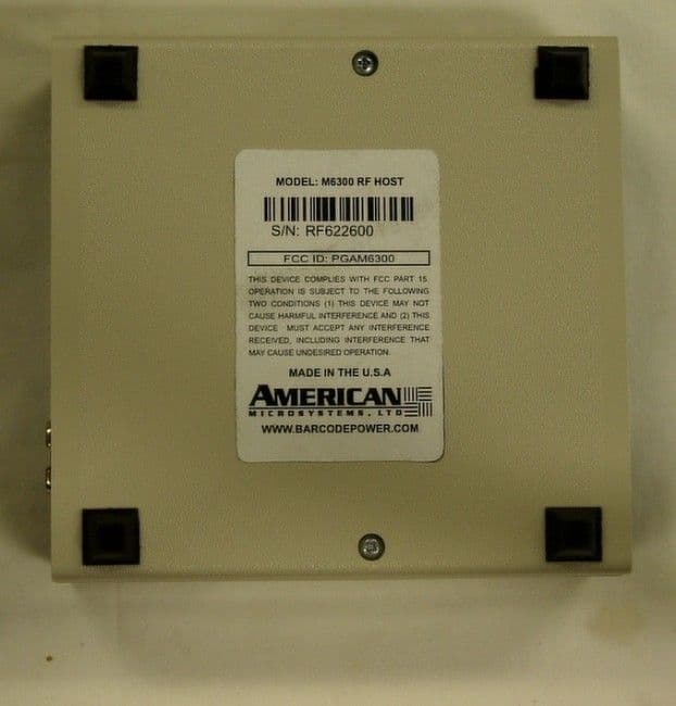
PGAM6300
May 06, 2002Wireless Bar Cade Decoder
Equipment Class
DXX - Part 15 Low Power Communication Device Transmitter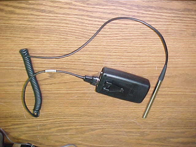
PGAM6000
Feb 19, 2001Handheld Wireless Barcode Reader
Equipment Class
DXT - Part 15 Low Power Transceiver, Rx Verified